Role of surface oxidation on the size dependent mechanical properties of nickel nanowires: a ReaxFF molecular dynamics study
Gurcan
Aral
 *a,
Md Mahbubul
Islam
 b and
Adri C. T.
van Duin
c
aDepartment of Physics, Izmir Institute of Technology, Urla, Izmir, 35430, Turkey. E-mail: gurcanaral@iyte.edu.tr; Fax: +90 232 750-7707; Tel: +90 232 750-7717
bSchool of Materials Engineering, Purdue University, West Lafayette, Indiana 47907, USA
cDepartment of Mechanical and Nuclear Engineering, The Pennsylvania State University, University Park, PA 16802, USA
First published on 21st November 2017
Abstract
Highly reactive metallic nickel (Ni) is readily oxidized by oxygen (O2) molecules even at low temperatures. The presence of the naturally resulting pre-oxide shell layer on metallic Ni nano materials such as Ni nanowires (NW) is responsible for degrading the deformation mechanisms and related mechanical properties. However, the role of the pre-oxide shell layer on the metallic Ni NW coupled with the complicated mechanical deformation mechanism and related properties have not yet been fully and independently understood. For this reason, the ReaxFF reactive force field for Ni/O interactions was used to investigate the effect of surface oxide layers and the size-dependent mechanical properties of Ni NWs under precisely controlled tensile loading conditions. To directly quantify the size dependent surface oxidation effect on the tensile mechanical deformation behaviour and related properties for Ni NWs, first, ReaxFF-molecular dynamics (MD) simulations were carried out to study the oxidation kinetics on the free surface of Ni NWs in a molecular O2 environment as a function of various diameters (D = 5.0, 6.5, and 8.0 nm) of the NWs, but at the same length. Single crystalline, pure metallic Ni NWs were also studied as a reference. The results of the oxidation simulations indicate that a surface oxide shell layer with limiting thickness of ∼1.0 nm was formed on the free surface of the bare Ni NW, typically via dissociation of the O–O bonds and the subsequent formation of Ni–O bonds. Furthermore, we investigated the evolution of the size-dependent intrinsic mechanical elastic properties of the core–oxide shell (Ni/NixOy) NWs by comparing them with their un-oxidized counterparts under constant uniaxial tensile loading. We found that the oxide shell layer significantly decreases the mechanical properties of metallic Ni NW as well as facilitates the initiation of plastic deformation as a function of decreasing diameter. The disordered oxide shell layer on the Ni NW's surface remarkably reduces the yield stress and Young's modulus, due to the increased softening effects with the decreasing NW diameter, compared to un-oxidized counterparts. Moreover, the onset of plastic deformation occurs at a relatively low yielding strain and stress level for the smaller diameter of oxide-coated Ni NWs in comparison to their pure counterparts. Furthermore, for pure Ni NWs, Young's modulus, the yielding stress and strain slightly decrease with the decrease in the diameter size of Ni NWs.
1. Introduction
Understanding oxidation phenomena and their effects on the mechanical deformation mechanism is currently an active area of research, and has caused immense interest and impact in science, engineering, technology, and most importantly in the fabrication of new nano materials with desired specific properties.1–10 In particular, reactive metallic nano materials readily oxidize during the industrial manufacturing, handling, and measurement processes, due to the high contact surface area with reactive oxidizers.1,3,8,9 As a consequence, the desirable (modification) or undesirable formation of native surface oxidation layers on nano materials protects the metal cores from contact with the outer surroundings, as well as leads to significant changes in the chemical,2,3,6,7 mechanical,10 electrical,6 magnetic2,5,6,10,11 and optical12 properties. The free surface of the oxidized shell layer of the reactive nano crystalline materials plays a direct role in controlling and manipulating the physical, chemical and mechanical properties of these materials, which mostly depend on the nature of surface defects, their density, thickness, etc.2–7,10–12 The core–shell structures of nano materials have been widely studied both experimentally and theoretically.5–9,11–14 There has been continuing interest and considerable systematic research efforts to precisely control the inherently complex oxidation process and unique associated properties at the nano level.2,4,6,10,12,14 Broadly speaking, nanoscale oxide coating is one of the challenges to developing novel nano materials with specific properties via controlling the surface oxide layer impurities,6 vacancies,4 voids,4 and morphology.2–6,10,11,14,15 However, it is very difficult to control these parameters separately.4,11,16–18Both Ni and Ni oxide are used as structural and functional nanomaterials in catalysis,14 gas sensors,4,6 biomedical5,7,12,19 and magnetic materials applications.5–7,10 More specifically, oxidized Ni has been extensively studied as an attractive transition metal oxide material in the fields of fuel cell electrodes,1,6 heterogeneous catalysis,12 antiferromagnetic layers,9,12,13 and electrochemical capacitors.2,14 For a variety of applications, tuning the Ni/NixOy core–shell structures with controlled size, shape and oxide surface microstructure significantly alters the properties of the nanoparticles as well as their performance and/or functionalities, compared to their un-oxidized counterparts.3,5–7,11–13 For example, the Ni/NixOy structure commonly consists of the metallic Ni core (ferromagnetic domain) and the NixOy layer (antiferromagnetic shells), which could be utilized for the isolation of the magnetic domain and for the induction of exchange coupling, but maintaining the oxidized layer homogeneity is exceptionally important.2,5 The magnetic performance and ferromagnetic properties of Ni nano materials as well as the correlation between the dimensions of the Ni NWs and the hysteresis behaviour have been intensively studied.12
The oxidation process is important, especially in nano crystalline reactive materials.9 The oxidation process for metallic Ni materials and the design of the Ni–NiOx interfaces, including the interfacial interaction between the oxidation shell layer and the metallic Ni core, the kinetics, and the resulting oxide structure have been extensively studied under various experimental conditions.9,11,20 In addition, significant efforts have been expended in the atomistic level investigations of the oxidation of reactive metallic nano materials.8 Particular interest has been geared toward the understanding of the factors controlling the growth kinetics of the oxidation process as well as external morphology and internal microstructural properties of the oxide layer.2,4,8,9,20 The factors influencing the oxidation processes are metal purity, orientation, temperature, oxygen partial pressure, environment (atmosphere composition), pre-treatments, and time of oxidation. The oxide growth mechanism on the Ni has recently been studied using reactive molecular dynamics (RMD) simulation.8,21,22 For example, Amiri et al. studied the characteristics of the hyper thermal Ni oxidation process as a function of temperature and crystallographic orientation.21 Their results indicate that the surface crystallographic orientation has little effect on the oxidation growth kinetics, which obeys the Langmuir growth model. However, increasing the surface temperature was accompanied by an increase in the oxidation rate of Ni surfaces. Assowe et al. investigated the corrosion of nanocrystalline Ni(111) surface with pure water at low temperature with or without various external electric field intensities between the metal and the solution using the ReaxFF potential.22 They have shown that the oxidation process strongly depends on the presence of the external electric field. Oxide film thickness increases linearly with increasing electric field intensity, which speeds up the corrosion of Ni. Moreover, the structural and morphological differences associated with the growth of this oxide film at the free surface depend on the presence of the applied external electric field. The oxidation on three Ni low-index free reactive surfaces ((100), (110) and (111)) was studied by Garruchet using variable charge molecular dynamics as a function of temperatures between 300 K and 950 K.8 In this study, their oxidation kinetic analyses revealed the existence of three different initial Ni-oxide growth steps: the dissociative chemisorption, the oxide island nucleation, and the lateral growth of the island. The kinetics of Ni oxide formation in the first step is dependent on the surface crystallographic orientation and temperature. Subramanian et al. used ReaxFF to investigate the initial oxidation kinetics of the Ni(100), the surface diffusivity of adsorbed oxygen, the oxide microstructure and morphology grown on metallic Ni substrates as a function of oxygen gas pressure and various values of externally applied electric fields at room temperature.23 They have shown that the initial oxide-film growth rate depends strongly on the applied electric fields as well as the pressure of molecular oxygen (O2).
Typically, reactive nano materials exhibit high reactivity towards oxidizer O2 molecules, which indicates that the oxidation process for metallic Ni NW occurs spontaneously even at room temperature,4,9,21 The mechanical tensile deformation mechanism and resistance depend critically on the oxide surface thickness, uniformity, micro-structural characteristics, and morphology of the surface (outer) as well as the interface (inner).2,4,21 The oxidation process results in an increased surface-to-volume ratio due to the diffusion of atoms. Furthermore, the role of the surface oxide is also contingent on the defects such as impurities, vacancies,4,5 and voids.4 Thus, the presence of the oxide shell layer may significantly change the deformation mechanism and degradation of the mechanical properties of nano crystalline Ni NW materials.24–28 The oxidized metallic NWs are expected to exhibit anomalous and interesting mechanical properties compared to their un-oxidized counterparts. Recent reactive MD studies showed that the oxide shell layer microstructure as well as the thickness on reactive metallic NWs have a strong influence on the mechanical deformation mechanism and related properties.21,24–27 The strength and ductility of metallic Al NWs primarily depend on the environment and the relevant microstructure of the oxidized Al shell layer.26 The Al NW's ductility and deformation length scale significantly increase with the oxide shell layer.26 Most importantly, the presence of native amorphous oxide shell layers on Al NWs change the plastic mechanical response from brittle to ductile transition behaviour and elastic properties. Skarlinski et al. reported that the oxidation of the films on nano crystalline copper significantly lowers the activation volume to initiate plastic deformation and related mechanical properties.24
In this study, we probe the oxidation of metallic Ni NWs to generate Ni–NixOy core–shell structures in the presence of an O2 environment at room temperature. We focus on the oxidation process and the resulting changes in the surface microstructure and effect of oxidation on the complex mechano-chemical tensile deformation process, plastic yielding behaviour, kinetics, as well as comparison of the mechanical responses and related properties with those of the un-oxidized counterparts.
2. Variable charge methods-based on the ReaxFF force field approach
The surface oxidation of reactive nano materials is considered an intrinsic factor that significantly affects the overall mechanical deformation mechanism and related properties. In this regard, the corresponding oxide shell layer, which includes complex defects such as dislocation activities, atomic lattice disordering, amorphization, lattice mismatch at the core–shell interface, and surface morphology, has a decisive impact on the strength of the nano materials.4,24–28 Since the initiation and emission of the dislocation mechanism are complex processes that couple chemical reactions (bond-making/bond-breaking) occurring at the free surface and/or interface between the oxide shell layer and the core region of NWs, it is therefore highly necessary to study relatively large systems over a longer time scale by variable charge methods.27 Conventional fixed charge potential models are too limited to describe the oxidation process because of the involved charge transfer during the chemical reactions.29 In spite of its significant importance on the nano scale, the role of the oxide shell layer in the mechanical properties of the core/shell (Ni/NixOy) materials has remained unexplored till now. Furthermore, the state-of-the-art nano experimental techniques have difficulty in quantifying the surface pre-oxidation and associated mechanical properties, due to the high reactivity of metallic Ni.16–18 However, recent reactive atomistic simulations using variable charge methods have successfully described the complicated reaction processes.8,30–32 The ReaxFF model is able to predict all the involved chemical reactions and coupled mechano-chemistry, by taking into account the overall charge-transfer, while retaining charge conservation.27,32,33 The classical MD simulation studies—which ignore surface oxidation effects—lead to the prediction of the elastic and inelastic mechanical properties of NWs that are incongruent with those observed experimentally.16–18,29,34–38 The several recently introduced reactive potentials provide a much more realistic approach that can be employed for systematic and detailed studies of oxidation of metals, metal alloys, and dissimilar metal/metal oxide interfaces, which were not previously possible with fixed charge methods.30–32,39 For example, one of the variable-charge potential schemes was proposed by Streitz and Mintmire to treat the atomic charges as dynamic variables, and was successfully applied to exploring the oxidation mechanism of metallic aluminium (Al) nano systems as a function of temperature, oxygen pressure, and orientation of the Al substrate.30,40–43 The ReaxFF method has already been used extensively to investigate the detailed complex oxidation phenomena occurring in various free surface metallic systems such as Si,44 Ni,8,32 Fe,27 and Al.30 In this study, ReaxFF is used to adequately describe the Ni/O interactions such as charge transfer, chemical reactions, and chemo-mechanical properties of the Ni/NixOy/O2 systems.32 Previous studies have demonstrated that the ReaxFF Ni/O potential predicted chemical reactions and physical properties are in proper agreement with quantum calculations and experimental information. We build on the successful use of this potential and apply it to investigating the oxidation of Ni with O2 molecules and its subsequent effect on the mechanical deformation and related properties. The most important feature of using the ReaxFF model is to comprehensively describe the coupling between mechanical and chemical interactions, and chemical reactions associated with the oxide and pure Ni NW during the deformation process. For example, the continuous stretching of Ni NW under tensile loading is associated with the local chemical reactions and the microstructural changes including chemical and physical disorder, bond straightening, bond switching, bond breakage, bond formation, etc.The interatomic potential energy, VReaxFF, in the ReaxFF model is a sum of a series of partial energies due to bonding, lone pair, over/under-coordination, valence interactions, energy penalty, conjugation, torsion, hydrogen bonding, van der Waals and Coulomb interactions, as noted in eqn (1):
| EReaxFF({rij}{rijk}, {rijkl}, {BOij}, {qi}) = Ebond + Elp + Eover + Eunder + Eval + Epen + Ecoa + Etors + Econj + EHbond + EvdWaals + ECoulomb. | (1) |
It is essential to ensure that the core/shell (Ni/NixOy) system is capable of maintaining appropriate basic intrinsic mechanical properties of the Ni NW with regard to the presence of the oxide layer at a finite temperature under the applied stress. Therefore, it is imperative to systematically understand as well as independently quantify the correlations and effects of the oxide shell layer on the tensile mechanical deformation mechanism and related properties of metallic Ni NWs. Here, the main motivation for our work is to gain atomic level insight, and to elucidate the processes of oxidation in an O2 oxidizer environment and the effects on the deformation mechanism and related properties of metallic Ni NWs subjected to tensile loading. For this reason, the large length scale classical MD simulations using the ReaxFF potential, as implemented in a parallel version of LAMMPS, are used to provide accurate and detailed answers to many related questions regarding intrinsic plastic mechanical properties with the correlation of surface oxide and size dependence occurring in Ni NWs.47 This atomistic-level understanding will be a guide in developing nano materials for their current and future potential nano scale technological applications.6
3. Simulation setup and computational details
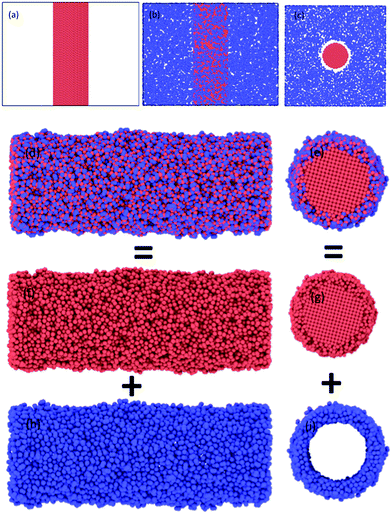
Representative snapshots in Fig. 1 demonstrate the comparative details concerning initial configurations before oxidation and the final configurations of oxide-coated NW, respectively. We constructed initial geometries of cylindrical NWs from [001]-oriented single-crystal metallic Ni NW with initial diameter of 5.0 nm and length of 15.136 nm from the perfect FCC Ni crystal, consisting of 27![[thin space (1/6-em)]](https://www.rsc.org/images/entities/char_2009.gif) 219 Ni atoms in vacuum, as shown in Fig. 1(a).
219 Ni atoms in vacuum, as shown in Fig. 1(a).
The created pure cylindrical Ni NW was inserted in the MD simulation box with a lateral size of 200.64 Å × 200.64 Å in the x and y directions and 151.36 Å long (uniaxial loading direction) in the z direction. The metallic pure Ni NW was exposed to O2 molecules as follows. First, 9000 randomly oriented O2 molecules were placed into the vacuum volume at about 6 Å from the top free surface of the cylindrical Ni NW, as shown in Fig. 1(b and c). The velocity of each atom was randomly assigned according to the Maxwell–Boltzmann distribution with a desired temperature of 300 K.48 The pressure of the O2 molecules (at least an initial distance of 3.0 A was maintained between the centers of two neighboring O2 molecules) surrounding the Ni NW was higher than the atmospheric pressure. The simulation of the oxidation of the metallic pure Ni NW was performed at 300 K by using the NVT ensembles with periodic boundary conditions in all directions.49 For each MD step (0.5 fs), the atomic charges and the equations of motion integration were performed based on the charge-neutrality constraint, Σiqi = 0 and the velocity-Verlet method, respectively.46,48 The O2 molecules act as a reactive oxidizing agent to metallic Ni NW. Finally, metallic Ni NWs were oxidized due to the dissociation of O2 molecules and the subsequent diffusion process of O radicals into the metallic Ni core. When the formation of the resulting oxide layer on the free surface reached ∼1.0 nm thickness, we stopped the oxidation simulation. Next, the un-reacted O2 molecules were removed from the vacuum environment. As a result, metallic reactive Ni NW was coated only with the native oxide (NixOy) shell layer. The formation of the oxide shell layer as well as the geometric reconstruction are shown in Fig. 1. The oxidized Ni NW consists of a metallic core surrounded by an oxide shell, e.g., core–shell structure as expected.
Prior to the tensile loading, each oxide-coated and pure Ni NW in vacuum was further relaxed under isothermal–isobaric ensemble. Dynamic relaxation based on the Nose/Hoover isobaric-isothermal ensemble (NPT) along the [001] direction was performed by equilibration under constant zero stress conditions at 300 K for all the Ni NWs in order to remove the residual stress.50 Once the system was fully relaxed, the relaxed Ni NWs were subjected to incremental uniaxial tensile loading via uniform scaling of the periodic z coordinates.
In order to determine the effect of the cylindrical cross-section and oxide shell layer in mechanical tensile properties, we investigated identically both the oxide-coated and pure Ni NW with three different diameters. We considered two additional initial diameters of Ni NWs, such as 6.5 and 8.0 nm, while keeping the same length. We performed exactly the same set of simulations by following the same procedure as mentioned above. The total numbers of O atoms involved in the oxidation of pure Ni NWs to form the oxide shell layer were 7658, 9968 and 10![[thin space (1/6-em)]](https://www.rsc.org/images/entities/char_2009.gif) 694 for initial D = 5.0, 6.5, and 8.0 nm systems, respectively.
694 for initial D = 5.0, 6.5, and 8.0 nm systems, respectively.
We applied a uniform uniaxial tensile strain loading at a constant strain rate of 0.01% ps−1 (108 s−1) on all relaxed Ni NW samples at a constant temperature using a Nose–Hoover chain thermostat.49 The strain rate was relatively high as compared to the experimental case of uniaxial tension. Next, we investigated the effect of the oxidation shell layer on the engineering stress–strain curves under the same loading conditions. The response of atomic uniaxial average stresses was evaluated based on the atomic virial stress formulation.48 The atomic strain was calculated with respect to the initial configurations at the end of the equilibration procedure.
4. Results and discussion
4.1 Mechanism of the formation of oxide-coated Ni NWs
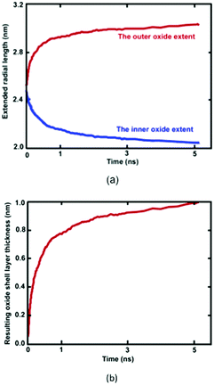
Reactive MD simulations were performed to investigate the oxidation growth process of metallic Ni NW in the O2 gas phase. We demonstrated that oxide-coated Ni NWs were generated from metallic NWs through the relatively simple and naturally direct oxidation in an O2 medium. Fig. 2 shows several distinct stages of the formation of the oxide shell layer on the free surface of metallic Ni NW at 300 K as a function of cumulative oxidation time in the O2 environment. The oxide shell layer on the nearly free surface of cylindrical Ni metallic NWs grows via the continuous dissociation of O2 molecules, dissociative chemisorption of O, diffusion of ions, and rearrangement of ions from one phase to another, consequently forming the oxide shell layer.8,21 Due to their high specific free surface contact areas on the nanoscale, the metallic Ni atoms in the NW are highly reactive towards O2 gas molecules. During the oxidation process, almost all O–O bonds of the impinging O2 molecule on the free surface of the metallic Ni NW are gradually broken to decompose into two O atoms. Dissociated O atoms react instantaneously with Ni atoms to form Ni–O bonds, accompanying dynamic charge transfer. This exothermic reaction releases a large amount of heat energy at a high rate. Transfer of the generated heat into the metallic core region facilitates the breaking of metallic Ni–Ni bonds in the vicinity of the surface region, and further drives the outward diffusion of the ions to react with O atoms. This mechanism is consistent with the observation of Campbell et al. in the oxidation of Al-nanoparticles.40 They reported that transportation of the generated heat into the system results in the formation of a large stress gradient in the developing oxide region. Consequently, they showed that the oxide and metallic core were under negative (tension) and positive internal pressure (compression), respectively. Thus, they predicted the presence of high stress gradients, assisted by a combination of the heat and dynamic charge transfer, may act as a driving force for the ionic species to the outward and inward diffusion through the developing oxide layer. Our observation suggests that the initial stress field due to the developing oxide layer additionally facilitates rapid movement of the Ni and O ions across the oxide layer in order the minimize the stress gradient.The thickness of the developing Ni oxide shell layer is carefully monitored when the metallic Ni NWs are exposed to the O2 environment. The time dependent growth of the oxide shell layer is simply governed by the inner and outer diffusion of O anions and Ni cations, supplied by the O2 environment and the metallic core of Ni NWs, respectively.4,15,27 The intrinsic properties of oxide-coated Ni NW materials are mostly controlled by these diffusion processes, which dictate the formation of oxide shell thickness, interface boundaries as well as the morphology of metallic oxide Ni NWs.15Fig. 2 reasonably helps us to visualize a physical picture of the oxide shell layer formation, the simultaneous diffusion of both Ni and O ions to the opposite boundaries of the oxide region, the inner and outer interface as well as the decrease in Ni and increase in O concentration in the oxide region, while metallic NW was oxidized as a function of time. The effective evolution of the resulting inner and outer diffusion length taking place on the reactive oxide region is roughly defined as the average position of the radial topmost 100 O atoms (radial outer (router) position) and of the radial lower 100 Ni atoms (radial inner (rinner) position). Thereby, the difference in the inner and outer diffusion length is equivalent to the total average oxide thickness on the free surface of metallic NW.27,32,40 The slopes of the curves in Fig. 2 clearly show that the kinetics of the oxidation process has two different oxide-scale growth regimes, i.e., oxide-scale growth proceeds in the initial stage with a very fast oxidation, followed by the slower oxide-scale growth rate, evident from the decreasing slope of the resulting oxide shell layer thickness curve as well as diffusion curves of Ni and O ions. Similar to the well-known characteristic behaviour of reactive metallic materials upon exposure to molecular oxygen, the diffusion of atoms and the oxidation rate in the resulting oxide shell layer initially increase rapidly.27,40–43 However, they then follow the limited growth regime and gradually decrease with increasing simulation time. The growth of the oxide shell layer with the oxidation time hinders further diffusion of both Ni and O of the outward and inward directions, and as such acts as a physical barrier. Consequently, the growing oxide layer progressively reaches some limiting value as its maximum thickness, beyond which the passivation film thickness remains almost constant and gradually behaves as an inert layer, which protects the underlying metallic Ni core from further oxidation. Thereby, the occurrence of oxidation gradually stops, and the underlying metallic Ni core remains physically isolated from O2 molecules. Finally, the core and oxide shell regions are roughly separated from each other by the inner interface. According to the kinetic gas theory, it should be noted that the growth of the oxide layer depends on the time of exposure to the molecular O2 environment and the partial pressure of oxygen gas. In our case, consumption of O2 molecules increases and as a result, the partial pressure of the O2 molecules decreases as a function of time. The higher the oxygen pressure, the easier the formation of the oxide shell layer.43 Thus, the diffusion of ionic species and the limiting thickness could result in a decrease in the molecular O2 pressure. The kinetic growth of the limiting oxide shell layer thickness follows approximately logarithmic behaviour from the Cabrera–Mott theory of metal oxidation as a function of the oxygen exposure time.
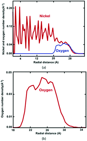
Formation of the resulting oxide shell layer, including O and Ni ion distributions and the oxide-coated Ni NWs diameter is shown in Fig. 3. During oxidation processes, the diffusion of both O and Ni ions in the oxide region causes significant volumetric changes in the NW.27 Geometrically, the newly formed oxide shell layer is also characterized by volume expansion after the oxidation processes are completed. Our observations for the smallest diameter of Ni NW indicate that the resulting NixOy oxide shell layer accumulated within the radial region from the inner radius rinner of ∼2.03 nm to the outer radius router of ∼3.00 nm. The difference between the outer and inner radius is equivalent to the average oxide shell layer thickness of ∼0.97 nm. The remaining diameter of the metallic single crystal structure Ni core is incorporated with the inner radius, as shown in Fig. 2(a) and 3(a). It is clearly seen that the shrinkage rate of the metallic Ni core, in addition to the extension rate of Ni ions progressively diminish with time. Finally, the inner (diameter of the Ni core) and outer (diameter of the oxide-coated NW) radiuses approach the limiting values, similar to the thickness of the total oxide shell layer. Thus, the oxide-coated Ni NW consists of the metallic Ni core, which shrank from an average diameter of 2.5 nm to ∼2.03 nm. The amorphous NixOy oxide shell was formed from an inner radius of ∼2.03 nm to an outer radius of ∼3.00 nm, wrapped around the core of metallic Ni NW, thereby forming an effective core/shell structure with oxide shell layer of ∼0.97 nm thickness. As a result, the average remaining diameter of the Ni core was reduced from 2.5 to 2.03 nm. The experimental results of Song et al. indicate that the surfaces of Ni nanoparticles of size 30 nm are covered by a non-uniform Ni oxide layer, whose average oxidation layer thickness was estimated at ∼1.0 nm.9 Moreover, their results clearly indicate that the oxide layer thickness is in the range of 0.5 to 2.0 nm, regardless of the particle diameter.
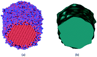
The inner and outer boundary morphologies of all oxide-coated NWs change significantly at the end of the oxidation process. The occurrence of the overall morphological details throughout the outer oxide shell layer at the internal (NixOy–Ni) and external (NixOy–O2) interfaces are highlighted in Fig. 4. Looking closely at the continuous oxidized shell layer boundaries in Fig. 4, the initial surface morphology of the pure Ni NW is dramatically changed to rough surface morphology along the length. The resultant morphology seems to exhibit a non-uniform isolated oxide ridge-like surface morphology at the whole external interface that is pertinent to the short-range microstructures, corroborating experimental observations.4,11,12 The rough free surfaces may also potentially behave as the most active sites during the mechanical deformation process.51
At the end of the underlying oxidation process, one can see that the formation of new oxide at the cylindrical Ni NW free surface is coupled with the reconstruction of the bonding at the surface, volume expansion, morphology and surface characteristics of the NWs.4,12,27 Formation of the non-uniform oxide shell layer resulted in an increase in the resulting mean diameter from the initial values of ∼5.0, ∼6.5 and ∼8.0 nm to the final values of ∼6.0, ∼7.6 and ∼8.9 nm, respectively. The changes in diameter correspond to ∼20, ∼17 and ∼11% increases, respectively. The volume of oxide-coated NWs increased due to a change in the molar volume between Ni and NixOy. The thicknesses of the oxide Ni NWs were approximately ∼0.971, ∼0.980 and ∼1.035 nm for the three different initial diameters of 5.0, 6.5 and 8.0 nm Ni NWs, respectively. Similarly, the radius of the metallic Ni core region shrank from ∼2.50, 3.25 and 4.00 nm to 2.03, 2.82 and 3.58 nm for D = 5.0, 6.5 and 8.0 nm, respectively. Therefore, the change in the diameter of the metallic Ni core region indicates the diffusion of oxidizers into the core of metallic Ni NW.
The average mass densities of oxide shell layers were calculated as ∼4.75, ∼4.79 and ∼4.91 g cm−3 for ∼6.0, ∼7.6 and ∼8.9 nm diameters of oxide-coated NWs, respectively. We evaluated their relative average mass densities of Ni atoms as ∼3.89, ∼3.96 and ∼4.07 g cm−3, and O atoms ∼0.86, 0.84 and 0.84 g cm−3 for D of ∼6.0, ∼7.6 and ∼8.9 nm of oxide-coated NWs. We also calculated the number densities per unit volume, which were 0.039, 0.040, and 0.041 cm−3 for Ni atoms and 0.032, 0.031, and 0.031 cm−3 for O atoms in increasing order of diameter, respectively. On the other hand, the average mass density of the core region remained the same ∼8.92 g cm−3 for all oxide-coated NWs, very close to that of experiment. This indicates the existence of two phases with different densities and degrees of crystallinity in the cylindrical Ni/NixOy system, which consists of the relatively denser phase of the metallic Ni core, surrounded by the less dense oxide phase. The total weight of the metallic Ni NWs increased by about ∼7.7, ∼5.8 and ∼4.2% for increasing order of diameter, respectively. Song et al. estimated that the statistical oxygen weight concentration was 7.65% by weight for the Ni nanoparticles of size 30 nm with ∼1.0 nm oxidation layer thickness.9 Zhou et al. studied the oxidation of the spherical metallic Ni particles at various temperatures.1 They found that the newly formed oxide layer contained a mixture of both crystalline Ni2O3 and NiO, which were highly coupled with temperature. Moreover, they indicated that as the temperature increased, the oxide shell layer average density decreased monotonically to 4.7–5.0 g cm−3 at lower temperatures, but increased to 5.5–5.7 g cm−3 at higher temperatures. Presumably, these results show the existence of two different oxide phases: Ni2O3 (4.84 g cm−3) and NiO (6.67 g cm−3), with different densities and degrees of crystallinity in the oxide region. The relative oxygen density in NiO is 1.42 g cm−3 and that in Ni2O3 is 1.40 g cm−3; the amorphous density of metallic Ni is 7.72 g cm−3.
The radial number density profile analysis shows that the maximum O atom concentration occurs around the middle of the oxide shell layer. However, the gradient in the oxygen concentration across the oxide layer exhibits three different regions with varying oxygen concentrations: the O2 environment-oxide interface (r = ∼32.2–27.0 Å), the oxide interior (central region) (r = ∼27.0–21.5 Å) and the metal-oxide interface (r = ∼21.5–19.5 Å), as shown in Fig. 3(b). Moreover, the greater percentage of O anions is found at the oxide interior, whereas the O anions percentage is slightly reduced in the metal-oxide interface as well as the oxide-oxygen environment interface. Thus, Ni and O atoms are not homogeneously distributed on the final oxide shell layer, which is strongly correlated with the depth of the oxide shell layer including the density and local microstructure. This suggests that the free surface as well as the interface between the core–shell boundaries of NW plays an important role in controlling the stress fields on initiation of plastic deformation, specifically due to a different local environment including lattice spacing, densities, coordination, etc.25–27 Moreover, these results also depend on the charge transfer between Ni and O ions, i.e., on the oxidation states (charge distribution states).
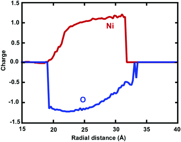
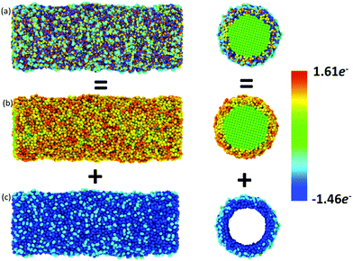
Atomic charges of Ni and O ions are associated with the local environment, including vacancies, voids or more complex defects.2,4 In this respect, charge transfer between O anions and Ni cations is an important feature determining the evolution of the mechanical properties, coupled with dislocations and surface oxide defects. The usage of the ReaxFF reactive force field enabled us to investigate the effect of charge transfer on the oxidation process. The spatial radial average charge distribution analysis provides insight into the oxidation process and the evolution of the charge states of cation and anion species. Fig. 5 shows the radial average atomic charge state distribution of each O and Ni atom, with respect to each radial shell (∼1 Å). In addition, Fig. 6 shows the evaluation of the charge state fluctuations on each atom and the non-uniform spatial charge distribution in the oxide-coated NW, when the thickness of the oxidation layer is ∼1.0 nm at the end of simulation. During the diffusion process, O ions instantaneously recombine with Ni atoms by exchanging charge between atoms to form Ni–O bonds in the oxide region as the thickness increases. Therefore, the atomic charge transfer facilitates the diffusion process, thus promoting the growth of the ionic oxide NiOx shell layer. We observed that the atomic charge states of Ni and O ion species were significantly reduced in the vicinity of the active oxide region, where the overall average net charge values were calculated as ∼0.894e− and ∼−1.12e− for Ni and O ions, respectively. Fig. 6 shows the non-uniform space-charge distribution in the oxide region. The low and high charge state values varied between ∼0.0 to −1.46e− for O ions and ∼0.0 to 1.61e− for Ni ions, and were consistently dependent on the local defects, bonding environment and the depth of the oxidized shell layer.21,40 The increase of charge values therefore indicates the significance of the dynamic electron transfer between the Ni and O atoms. As an indication of the charge distribution from Fig. 6, the maximum and minimum atomic charge values in the oxide region reveal that the exchange of charges between atoms is higher around the middle of the oxide shell layer, but they are partially charged at the interface and the free surface.40 The charge states on a Ni atom vary largely, assuming the maximum value when close enough to an O atom, and zero when far away. Therefore, in a predominantly metallic core region, the atomic charge of the Ni atom is close to zero. The chemical bonding between Ni and O ions has more electrostatic character, due to the additional attractive force between the positively and negatively charged ions.45 The charge dependent nature of electrostatic interactions accounts for both mutually short and long-range attraction as well as repulsion dependency. The strength of oxide-coated NWs may primarily depend on the competition between the complex nature of charge redistribution and the surface reconstruction including atomic bonding and imperfections on the oxidized surface. Besides, the charge transfer is directly correlated to the Ni–O bonding strength.39 The stretching of NWs induces the distortion and change of the local bonding environment of each atom, and at the same time, the electrostatic force may dominate the oxide effect on the mechanical properties of NWs. Mechanically induced chemical reactions may initiated by bond breaking and formation from the interface between Ni and NixOy. The pre-oxidized shell layers at the free surface of the Ni NWs act as both sources and sinks for dislocations and assist dislocations to escape at the beginning of the plastic strain. The mechanical properties of reactive Ni NWs are intrinsically sensitive to the free surface oxidation layer and interface between Ni and NixOy, owing to the electrostatic interaction between O and Ni atoms. Therefore, in the oxide surface, the electrostatic nature of bonding, atomic charge redistribution, and the surface reconstruction play a critical role in the nucleation and emission of dislocations, and consequently, affect the mechanical properties of the materials.
4.2 Microstructure analysis and properties of the resulting oxide shell layer
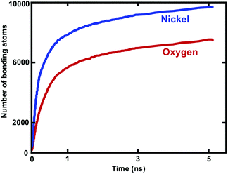
The complex microstructure of the surface oxide shell layer on the Ni NWs has a major effect on their functionality in many practical applications.4–6,19,52 The existence of an oxide layer on the free surface of NWs is also believed to govern the strength and mechanical deformation properties of Ni–NixOy nano materials.24,26,27,32 During the oxidation process, the diffusion of Ni and O atoms associated with subsequent chemical reactions changes the overall local microstructures of various phases and intrinsic surface properties.5,6,11,15 Thus, a detailed understanding of the intrinsic properties of the oxide-coated Ni NWs, including the local structural arrangement, composition, atomic correlation, etc. is considerably important.4–6,19 After oxidation of the Ni NW with O2 molecules, the oxide-coated metallic Ni NWs act as core (Ni) and oxide shell layer (NixOy) nanostructures, where the shell layer acts as a source for dislocations as well as assist dislocations to escape at the beginning of the plastic strain. The changes in the local short-range crystal structure, correlations and properties of the formed Ni/NiOx NWs shell layer are characterized by using the analysis of radial pair distribution functions (RDF), coordination numbers, bond-angle distributions and the O number density profiles.In the oxidation process, out of 9000 O2 molecules in the gas phase, 42% of the O2 molecules were consumed to form the NixOy oxide shell layer for D = ∼5.0 nm. The total number of 7658 O atoms reacted to form the oxide shell layer on the free surface of metallic NW. However, the total number of 9671 Ni atoms were involved in the bonding with the O ions, as shown in Fig. 7. Therefore, ∼65% of the overall Ni atoms remained unreacted with O atoms, which acted as the metallic core region. The oxide nucleation and growth is strongly correlated with the consumption of metallic Ni core atoms as well as O atoms. Overall, ∼49.7% of the total Ni and O atoms participated in the formation of the oxide shell layer (NixOy) for D = 5.0 nm. We also calculated the total overall number of reacted (oxidized) and unreacted (un-oxidized) atoms. The ratios of unreacted/reacted atoms in the core/shell structure were ∼1.02, ∼1.54 and ∼2.32 for D = ∼6.0, ∼7.6 and ∼8.9 nm, respectively. We observed that the higher surface areas in the case of larger diameters resulted in larger unreacted/reacted atom ratios. We also calculated the ratio of Ni/O atoms in the oxide shell layers, which were ∼1.29, 1.28 and ∼1.34 for D = ∼ 6.0, ∼7.6 and ∼8.9 nm, respectively.
Fig. 8 shows the calculated RDF of Ni–O, Ni–Ni, and O–O pairs. For all oxide-coated Ni NWs, the first sharp peak appears at around 1.82 Å in the Ni–O RDF, indicating the average bond distance between Ni and O atoms in the oxide NiOx structure, which is in good agreement with the measured distance of 1.94 Å reported by Caputi et al.52 However, Garruchet et al. reported a slightly larger average Ni–O bond distance of 2.0 Å.8 The large variations in the Ni–O bond length in the microstructure of the Ni oxide region (NiOx) data can be attributed to the purity of the metallic Ni, surface preparation, and the oxidation procedure. Importantly, the shortening of the Ni–O bond-length indicates an increased oxide density. The second peak of the Ni–O RDF at around 2.45 Å corresponds to the distance of the second nearest neighbour in the NiOx structure. Pair distributions indicate that O ions in the oxide region are organized in a short-range ordered structure with Ni ions. It is interesting to note that the RDF for O–O exhibits a sharp and well defined peak at 1.35 Å in the RDF curve, corresponding to un-dissolved O2 molecules at the outer surface of NW. Moreover, two more peaks appeared at 1.95 Å, and 3.4 Å, as seen in Fig. 8. The Ni–Ni bond length is around 2.65 Å. The RDFs for Ni–O, Ni–Ni, and O–O also showed almost similar peak positions for all oxide-coated NWs with three different diameters.
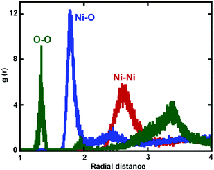 | ||
| Fig. 8 Radial pair distribution functions g(r) for Ni–O (blue), O–O (green) and Ni–Ni (red) in the shell of the oxide region are shown. | ||
The chemical composition, relative atomic percentages of Ni and O atoms and bonding nature of the oxide region of Ni NW were also determined via calculations of coordination number. By integrating the first peak of the Ni–O partial pair distribution function (g(r)) over the first peak up to 2.5 Å (at which there is the first minimum of the Ni–O pair distribution function), the average coordination number of Ni atoms with O atoms was computed to be 2.67 for the oxide-coated NW with diameter ∼6.0 nm. The average coordination numbers were found to be quite sensitive to change in the integration cut-off distances. We further analysed the atomic structures, such as the oxide shell layer on the free surface of metallic Ni NW with diameter 5.0 nm, which has a predominantly amorphous structure and is mainly composed of a mixture of one fold coordination (NiO ∼ 9.62%), twofold coordination (NiO2 ∼ 44.50%), threefold coordination (NiO3 ∼ 43.43%), and fourfold coordination (NiO4 ∼ 2.44%). These results also indicate contributions of the coexistence of NiO, NiO2, NiO3 and NiO4 phases in the constituents of the oxide-coated NW. The coordination numbers of the O atoms vary widely between 1 and 4 O atoms around Ni atoms. In contrast, the number of Ni atoms with 4-fold coordination is actually very small. We calculated the average total coordination number of Ni around O atoms as ∼2.93 in the oxide shell layer region. We observed that the average number of O atoms coordinated to Ni atoms was slightly larger, compared to the Ni atoms coordinated by O atoms. Thus, the non-uniform distribution and chemically disordered amorphous oxide shell layer crystal structures are relatively richer in Ni atoms than the O atoms. In addition, we noted that the local structure of the oxide shell layer was a mixture of 1-fold (ONi ∼ 3.97%), 2-fold (ONi2 ∼ 12.56%), 3-fold (ONi3 ∼ 35.67%), 4-fold (ONi4 ∼ 37.01%), and (ONi5 ∼ 0.78%) tetrahedral coordinated Ni sites, but most of the O atoms were 4-fold coordinated, whereas only 0.78% had a coordination of 5 by Ni atoms. The developed oxide shell layer on the free surface of Ni NW had an amorphous structure, and was therefore primarily composed of a large distribution of mixed fold coordination numbers between nearest neighbours of Ni–O atoms. Besides, the mixed charge states of O in NiOx are correlated with these mixed coordination numbers. We also calculated the Ni average coordination number in the oxide regions for all the oxide-coated NWs. The average coordination numbers for the Ni atoms were ∼2.30, ∼2.20 and 2.02 for the D = ∼6.0, 7.6, and 8.9 nm, respectively. More importantly, the mixed and non-stoichiometric (NixOy) oxide layers may significantly influence the kinetics of the mechanical deformation mechanism and related properties of Ni NWs.26 These results are consistent with the previous studies. For example, various stoichiometric oxides such as Ni2O3, Ni2O2 and NiOx were reported during the oxidation of nano-Ni structures. Symianakis et al. found that during deposition of Ni ions, Ni atoms combined with the neighbouring O ions to form the NixOy oxides where x and y ≤ 4.20 Moreover, they speculated that the more negatively charged components of the O might be attributed to species like Ni2O, Ni3O2 and Ni4O4, while the less negatively charged components to species like NiO2.20 Barrientos et al. studied the formation as well as structural properties of the 30–50 nm Ni/Ni oxide nanoparticles using electron diffraction and X-ray diffraction techniques.19 Their results indicated the presence of mixed NiO, NiO2, of Ni2O3 oxides and Ni phases inside the limiting sphere oxide shell layer region. Zhou et al. indicated that in the oxide region, the oxygen concentration was quite uniform and was comprised mainly of Ni2O3 and NiO oxide phases.1
4.3 Influence of pre-oxidation treatment effects on the size dependent tensile mechanical properties of Ni NW under tension
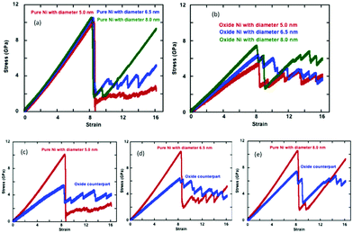
We represent the engineering stress–strain relationships for the pure and oxide-coated NWs subjected to uniaxial constant tensile loading at 300 K as a function of cylindrical cross-section in Fig. 9. Table 1 lists the tensile mechanical properties such as elastic modulus, yield stress and strain for the pure and oxide-coated Ni NWs. The comparison of the results in Fig. 9(a) indicate that stress–strain curves of pure Ni NWs are overall very similar to each other in the elastic regime for the three different diameters such as the 2.5, 6.5 and 8.0 nm at the same length. However, the negligible variation, which was observed, is due to the fact that when the NWs with different diameters were constructed from the crystalline Ni, they resulted in a slightly different surface structure. The stress–strain curve shows a single and abrupt drop in stress after the onset of plastic deformation, but the amplitude difference is quite notable for the largest diameter as compared to the smaller diameter NWs. Tensile yield stress values of 10.1, 10.50 and 10.55 GPa increased slightly with increasing diameter of 5.0, 6.5 and 8.0 nm, respectively, for pure Ni NWs. The increase in the diameter reduced the onset of plastic deformation strain values to 8.50%, 8.45% and 8.25%, respectively. Thus, there was no significant variation in overall yield strain. Huang et al. showed that the yield strain of Ni NWs is independent of both the strain rate and cross-sectional size, which agrees with our results.53 However, there is a slight shift in yield strain to a smaller value with the increase in diameter. Finally, our results suggest that the Young's modulus, yield stress, and strain exhibit a weak correlation with the variation of the diameters of the NWs as compared to the oxide-coated counterparts.| Diameter (nm) | Thickness (nm) | Ratio | ε z (%) | σ z (GPa) | E (GPa) |
|---|---|---|---|---|---|
| Pure = 5.0 | 8.50 | 10.10 | 120.2 | ||
| Pure = 6.5 | 8.45 | 10.50 | 126.2 | ||
| Pure = 8.0 | 8.25 | 10.55 | 128.4 | ||
| Oxide-coated = 6.0 | ∼0.971 | ∼1.02 | 8.35 | 5.40 | 65.6 |
| Oxide-coated = 7.6 | ∼0.980 | ∼1.54 | 8.27 | 6.35 | 77.9 |
| Oxide-coated = 8.9 | ∼1.035 | ∼2.32 | 8.10 | 7.35 | 92.1 |
The metallic Ni NWs are covered with a native oxide shell layer with a thickness of ∼1.0 nm. Fig. 9(b) represents the engineering tensile stress–strain curves for the oxide-coated Ni NWs with three different diameters. Interestingly, the stress–strain behaviour shows a strong correlation of the predicted mechanical properties as a function of the diameters of the oxide-coated NWs. The presence of oxide layers reduces the mechanical properties compared to the pure NWs, as shown in Fig. 9(b). The calculated yield stresses are 5.4, 6.35 and 7.35 GPa, occurring at the yield strains of 8.35%, 8.27% and 8.10% for the diameters of ∼6.0, ∼7.6 and ∼8.9 nm, respectively. The increase in the diameter of the oxide-coated NWs slightly decreased the yield strain. The results also indicated that the diameter of the oxide-coated Ni NWs significantly affects the yield stress and Young's modulus.
The variation in tensile engineering stress–strain curves for each pair of the pure sample and its oxide-coated counterpart of the initially similar un-oxidized diameters is shown separately in Fig. 9(c–e). The size effect of mechanical properties is more sensitive for the oxide-coated Ni NW, as compared to the pure counterpart. It is important to note that the presence of the pre-oxide shell layer on the metallic Ni NW significantly decreases the yielding stress to onset of plastic deformation with decreasing the oxide-coated Ni NW diameters, as seen from Fig. 9(c–e). The larger variations in the yield stress are obvious from the figures with the oxide layers, although the yield strains are quite similar. It was found that the differences in yield stress were uniquely related to the pre-oxidized shell layer and the size effects. For example, the difference in the yield stress between the pure and the oxide counterparts decreased with the increasing diameters. The yield strength was ∼10.1 GPa for the smallest pure Ni NW with D = 5.0 nm, while it decreased markedly to ∼5.4 GPa for its oxide counterpart with D = ∼6.0 nm. The decrease in the yield strengths of oxidized structures were ∼46.5, ∼39.3 and ∼30.3% as compared to the pure Ni case for the increasing order of D = ∼6.0, ∼7.6 and ∼8.9 nm, respectively. Notably, this indicates the size-dependent oxide softening effect on the mechanical properties with the decrease in diameter. The yield stress drops suddenly past the elastic limit, and subsequently, the material undergoes plastic deformations with the further increase in applied strains. The stress relaxation causes a zigzag shape of stress–strain response due to the atomic rearrangements in the plastic deformation regime, as shown in Fig. 9. Wen et al. also observed the same characteristic behavior in the case of the tensile deformation of Ni NW; once the strain exceeded the yield point, the stress dropped rapidly to about 3.0 GPa, and then increased in a repeating increase/decrease cycle with the further applied strain, due to the phase transformation inside of the NW.37
However, the calculated values of Young's modulus for the Ni NW were also strongly correlated with the presence of the pre-oxidized shell layer. The calculated Young's modulus of the oxide-coated Ni NWs were 65.6, 77.9, and 92.1 GPa as the diameter of oxide Ni NWs increased to ∼6.0, ∼7.6 and ∼8.9 nm, respectively. The Young's modulus value for the ∼6.0 nm diameter oxide-coated NW was ∼54.6% smaller than the value of 120.2 GPa for its pure NW counterpart. The Young's modulus was 128.4 GPa at the strain of 10.55% for the pure Ni NW with ∼8.0 nm diameter, and for its oxide-coated counterpart, the Young's modulus was 92.1 GPa at the strain of 8.1%, with the corresponding Young's modulus ratio of ∼71.7. Interestingly, the pre-oxidation effects on the reduction of Young's modulus became less significant, only ∼45.7, ∼38.3 and ∼28.3% with the increasing diameters.
We observed remarkable differences in the values of yield stress and Young's modulus between the pure and oxide-coated Ni NWs with the variation in the NW diameters. Once metallic Ni NW were oxidized, the formation of oxide shell layers on the metallic Ni NW acted as new dislocation sources and stress concentrators, consequently lowering the activation stress of plastic deformation.27 In the cases of oxide-coated NW with small diameters, additional complexity arose from the interplay between unreacted and reacted atoms. We considered the ratio of total reacted and unreacted atoms in the Ni/NixOy system to explain this significant drop in yield stress, the change in the deformation mechanisms, and the initiation of dislocation motions. The overall ratios between the unreacted and the reacted total number of atoms in the core–shell system were calculated as ∼1.02, ∼1.54 and ∼2.32 for D = ∼6.0, ∼7.6 and ∼8.9 nm, respectively. The unreacted/reacted ratio of oxide coated Ni NW had a relatively smaller value for the smaller diameter, which had a pronounced effect on initiating the plastic deformation mechanisms, and on the mechanical properties. Since the small number of core Ni atoms in the NW cannot bear the tensile load, the required external applied stress to activate dislocation sources and plastic deformation decreases. Thus, the yield stress and Young's modulus decrease with decreasing the unreacted/reacted ratio. Smaller unreacted/reacted atom ratios indicate a relatively larger oxide shell region-to-volume ratio and cause an abundance of imperfections and a higher degree of broken symmetry at the overall NW, including non-uniform stress distribution and lattice mismatch at the core–shell interface.15 The oxide shell coated NW with the smallest diameter—with a higher surface-to-volume ratio—is more prone to emitting the dislocations, compared to the larger diameter NWs.
We further compared our calculated mechanical properties for the pure Ni NW with the previous MD simulation results, which indicated good agreement. For example, the temperature and strain rate dependence of the tensile properties of ultrathin Ni NWs in the 〈100〉 orientation with D = 4, 5 and 6 nm with the same length of 15 nm were investigated by Wang et al. using the EAM potential model.54 They showed that the elastic modulus and the yield strength of the NWs gradually decreased with the increase in temperature. Their reported elastic moduli and yield strengths at 300 K were in the range of 116–119 GPa and 11–12 GPa for all Ni NW, respectively, under different strain rates, in conformity with our results. For example, our simulations showed that the yield stress and Young's modulus of pure Ni NW with diameter 5.0 nm were 10.1 (GPa) and 120.2 (GPa). Wen et al. reported the properties and mechanical deformation processes of metallic Ni NWs using the quantum corrected Sutten–Chen potential model.37 The [001] oriented crystalline Ni NW with an initial diameter and length of 2.96 nm and 14.1 nm, respectively, at 300 K exhibited no significant effect of strain rate on the elastic properties of Ni NW, but had some influence on the yield stress and the elastic limit of the Ni NW. For the constant strain rate of 0.1% ps−1, the Ni NW deformed elastically up to ∼11.17% strain with the yield stress of 8.62 GPa. However, their estimated Young's modulus value of 80.6 GPa is significantly lower than that of our result for pure Ni NWs. Using the EAM potential model, Ferdous et al. pointed out that the defect sites in Ni NWs cause stress concentration and eventually serve as the initiation sites for the onset of plastic deformation, as well as directly assist the dislocation nucleation.36 The effect of surface defects is more prominent at small diameters. Ikeda et al.35 observed that Ni NWs show elastic behaviour up to 7.5% strain with a yield stress of 5.5 GPa at lower strain rates of 0.5 and 0.05% ps−1. They observed that the maximum stress at the onset of plastic deformation dropped rapidly by ∼50%, increased again, and then decreased in a repeating loading/plastic deformation cycle with increasing strain for lower strain rates. However, for a higher strain rate of 5% ps−1, the maximum stress of 9.5 GPa occurs at 15% strain and a very different behaviour. Branicio et al. investigated the effect of strain rates and cross-sectional sizes on the mechanical properties of pure Ni NWs under uniaxial strain at 300 K using the embedded potential model.34 They show that mechanical properties are nearly independent of the cross-sectional size, but depend on the surface effects, e.g., the fraction of particles on the surface and in the volume of the NW. They obtained the yield stress of 9.4 GPa at a strain value of 10.5%, which are comparable to our yield stress of 8.45 GPa at a strain of 10.5%. Specifically, our results indicate that the yield strain for D = 6.5 nm was obtained at around 10.5% with 8.45 GPa, which is in proximity to the value of 9.5 GPa strain (10.5%) provided by Branicio et al. It indicates that our yield stress is almost ∼10% lower than their results. They indicated that the Young's modulus values vary between ∼90–114 GPa as a function of the cross-section of Ni NWs. However, the Young's moduli of oxide-coated Ni NW with D = ∼8.86 nm is 92.1 GPa, which is within the range.34
The comparison of the theoretically predicted mechanical strength of Ni NWs with the existing experimental measurements shows that the theoretical results are significantly lower than the experimental values.16–18,55 Shan et al. showed that the processing of sub-micrometer Ni crystals micro fabricated into pillar structures results in a high density of initial defects.56 Therefore, the difference in predicting their elastic properties could be highly attributed to these initial surface defects of NWs, indicating the importance of the pre-oxidized surface shell layer. More importantly, the strain rates of MD simulations are significantly higher than the experimental studies. Peng et al. presented mechanical behaviour, deformation mechanism, and mechanical properties for single crystalline Ni NWs with different diameters and two different crystalline orientations ([111] for 100 nm diameter NWs and [112] for 200 to 300 nm diameter NWs) through uniaxial in situ tensile tests in a scanning electron microscope.16 They found a clear size effect in the average fracture strength, where the value was 2.43 GPa for diameter of 200 to 300 nm, while it was 1.36 GPa for 100 nm diameter Ni NWs. In another similar work, Peng et al. studied the strain-rate effects for single-crystal Ni NWs with different diameters ranging from 80 to 300 nm, both experimentally and computationally, to determine the ultimate tensile strength (UTS) and activation volume parameters.17 They indicated that Ni NWs are highly sensible on the strain-rate. For example, the smaller sample diameter and higher strain-rate give the larger UTS. Moreover, a higher strain rate always results in a larger UTS in the same group with similar diameters. More specifically, the UTS was ∼1.2–1.5 GPa for the 200 to 300 nm diameter group, and was ∼2.5–3.4 GPa for the 100 nm diameter group. The yield stress of ∼5.4 GPa for our oxide-coated D = ∼6.0 nm NW was a close match to that of experimental NW Ni (about 3.4 GPa).
4.4 Tensile mechanical deformation mechanism of oxide-coated Ni NW
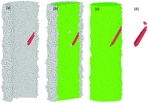
The common neighbour analysis (CNA) in OVITO was used to analyse the presence and identify the generation of any defects, and subsequent changes in the crystalline structure of the NWs.57 In Fig. 10–14, the atoms are coloured according to the CNA values, which indicate the local atomic crystallinity of Ni NWs. In the analysis, the creation of defects in Ni NW was identified as the alteration of the fcc stacking sequence to the hcp stacking order. Fig. 10–14 indicate that the atomic arrangement in the oxide region and part of the interface (Ni/NixOy) (coloured with grey) are characterized as unknown structures, which means that the nature of oxidized atoms at the oxide shell region characteristically encounter totally different local environments from those of un-oxidized atoms (fcc) within the volume of oxide-coated NW. Such high concentrations of disordered structure (amorphous phase) at the native oxide shell layer effectively promote the availability as well as accumulation of nucleation of dislocation sites, thus enhancing the probability of initiation of dislocation activity at the beginning of the plastic deformation. However, these effects are more pronounced in the cases of smaller diameters. Therefore, it might be the reason why the earliest nucleation of dislocations prefers the oxide region and the yield stress for the onset of plastic response is much smaller than for the pure Ni NW. Moreover, the combination of the potentially operative sites of the oxide region with the external applied tensile loading provides additional driving force to effectively facilitate the onset of plasticity and regulate the dislocation dynamics during tensile loading, which leads to their reduced mechanical strengths compared to pure Ni NWs.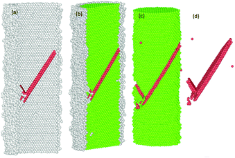 | ||
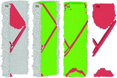
Fig. 11 The formation of the first SF on the (11![[1 with combining macron]](https://www.rsc.org/images/entities/char_0031_0304.gif) )-slip plane and the second partial dislocation on the (111)-slip plane, which is blocked by the SF. )-slip plane and the second partial dislocation on the (111)-slip plane, which is blocked by the SF. | ||
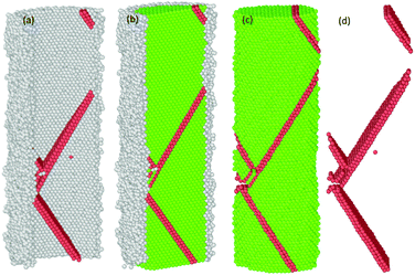 | ||
| Fig. 12 Third partial dislocation nucleation is started from the interface of the NW to form of the second SF. | ||
 | ||
| Fig. 13 Third partial dislocation nucleation is initiated from the interface of the NW to form the second SF, immediately after the annihilation of the first SF. | ||
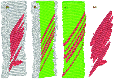 | ||
Fig. 14 The spatial distribution of the successive formation and rearrangement of the multiple parallel intrinsic and extrinsic SFs on the (11![[1 with combining macron]](https://www.rsc.org/images/entities/char_0031_0304.gif) ) slip plane in the NW. ) slip plane in the NW. | ||
Previous studies indicate that the resulting plasticity in any oriented fcc crystalline Ni nano material occurs predominantly by the emission and propagation of partial and full dislocations.17,54,57,58 The presence of multiple energetically favourable close packed slip systems ({111}〈112〉 and {111}〈110〉) on the {111} plane under tension loading facilitates plasticity in the material regardless of the variation in sample size, crystalline orientation and the applied strain rate.16,17,29,37,55,58,59 In our case, the plastic deformation process of both the pure and oxide-coated Ni NWs starts from the free surface and the interface of the oxide region via rapid emission of dislocations at the preferential slip systems.29,58 For example, the details of the evolution of the plastic deformation process including defects in the oxide-coated NWs with diameter of ∼7.6 nm are shown in Fig. 10–14. We observed that the initiation of dislocations collaborated with the hcp stacking order and unidentified structures. Therefore, it is hard to say that initial dislocations were emitted from the free surface of the oxide-coated NW. It was shown that at the beginning of the plastic strain, the simultaneous emission of initial intrinsic partial dislocation took place at the Ni–NixOy interface along the (11![[1 with combining macron]](https://www.rsc.org/images/entities/char_0031_0304.gif) ) slip plane. At the same time, more specifically, the rapid drop of overall growth stress associated with the onset of plasticity was primarily induced by the initiation and propagation of the partial dislocations. With further strain increase, the leading partial dislocation was propagated and annihilated at the opposite side of the NW to form a stacking fault (SF) in the cross-section of the NW. Then, the second partial dislocation was also simultaneously nucleated from the interface, which is in the vicinity of the final intersection of the first dislocation and acts as a source of dislocation nucleation. The gliding of the second dislocation along the (111) slip planes intersected the SF plane, then, its further propagation and activities were immediately blocked. The dislocation blockage acts as an effective barrier for the second partial dislocation, as shown in Fig. 11. In addition, the emission of the third partial dislocation occurs on the same interface point of the final intersection of the first dislocations. Its glide results in the creation of the second intrinsic SF on the same (111) slip plane, as shown in Fig. 12. The intersection points between the first and second SF form a pair at the interface. Upon continued tensile loading, the annihilation of the second stacking fault begins to move further away from the initiated interface to the opposite side of the finally annihilated interface. As soon as the second SF is annihilated, another new partial dislocation is nucleated from the annihilated side of the interface, which glides to the opposite side on the (111) plane and eventually intersects with the first dislocation at the interface, resulting in the configuration seen in Fig. 13. At this point, it is likely that the second (111) oriented initial SF is progressively transformed into a new (001) reoriented SF. It is found that the propagation of annihilation and creation of intrinsic new SF activity results in the subsequent sharp increase and decrease in overall stress (as the zigzag stress–strain curve), respectively. Further analysis revealed that the similar deformation processes, including formation of both the coplanar intrinsic and extrinsic SF, occur repeatedly and eventually lead to the reorientation and formation of multiple parallel intrinsic and extrinsic multi-layered SF arrangement on the (11
) slip plane. At the same time, more specifically, the rapid drop of overall growth stress associated with the onset of plasticity was primarily induced by the initiation and propagation of the partial dislocations. With further strain increase, the leading partial dislocation was propagated and annihilated at the opposite side of the NW to form a stacking fault (SF) in the cross-section of the NW. Then, the second partial dislocation was also simultaneously nucleated from the interface, which is in the vicinity of the final intersection of the first dislocation and acts as a source of dislocation nucleation. The gliding of the second dislocation along the (111) slip planes intersected the SF plane, then, its further propagation and activities were immediately blocked. The dislocation blockage acts as an effective barrier for the second partial dislocation, as shown in Fig. 11. In addition, the emission of the third partial dislocation occurs on the same interface point of the final intersection of the first dislocations. Its glide results in the creation of the second intrinsic SF on the same (111) slip plane, as shown in Fig. 12. The intersection points between the first and second SF form a pair at the interface. Upon continued tensile loading, the annihilation of the second stacking fault begins to move further away from the initiated interface to the opposite side of the finally annihilated interface. As soon as the second SF is annihilated, another new partial dislocation is nucleated from the annihilated side of the interface, which glides to the opposite side on the (111) plane and eventually intersects with the first dislocation at the interface, resulting in the configuration seen in Fig. 13. At this point, it is likely that the second (111) oriented initial SF is progressively transformed into a new (001) reoriented SF. It is found that the propagation of annihilation and creation of intrinsic new SF activity results in the subsequent sharp increase and decrease in overall stress (as the zigzag stress–strain curve), respectively. Further analysis revealed that the similar deformation processes, including formation of both the coplanar intrinsic and extrinsic SF, occur repeatedly and eventually lead to the reorientation and formation of multiple parallel intrinsic and extrinsic multi-layered SF arrangement on the (11![[1 with combining macron]](https://www.rsc.org/images/entities/char_0031_0304.gif) ) slip plane in the NW, as shown in the Fig. 14. The identical dislocation mechanisms are observed in the all oxide-coated NWs.
) slip plane in the NW, as shown in the Fig. 14. The identical dislocation mechanisms are observed in the all oxide-coated NWs.
5. Conclusions
We have elucidated the size-dependent mechanical properties of the cylindrical pure metallic (as references) and oxide-coated Ni NWs, subjected to tensile loading. Our atomistic-level study not only explains the oxidation mechanism of Ni NWs with O2 oxidizers, but also predicts the correlation between mechanical tensile deformation properties with the existence of a pre-oxidized shell layer. The free surface of metallic reactive Ni NWs is readily oxidized by O2 molecules under ambient conditions. During the oxidation process, extensive atomic rearrangement takes place in the growth of the surface oxide shell layer and interfaces. We found that under uniaxial tensile loading, the tensile strength and properties of the oxide-coated Ni NWs are highly correlated with the presence of the complex surface oxide shell layer. Furthermore, unique existing features of the surface oxide shell layer promote dislocation sites, acting as a productive source to facilitate the onset of plastic deformation activities. Thus, oxide-coated Ni NWs exhibit anomalous and interesting mechanical properties such as the reduction in mechanical strength, including Young's modulus and yield stress under tensile loading as compared to the pristine counterparts. In addition, we identified that the influence of the pre-oxidized shell layer on the yield strain was small, but the yield stress and Young's modulus were extremely sensitive to the decreasing diameter as compared to the response of the un-oxidized counterparts. Specifically, the pre-oxidized shell layers were found to lower the stress of dislocation nucleation, thus leading to the softening of Ni NW. Moreover, it can be inferred that the pre-oxidized shell layer and diameter are the two combined key factors controlling the tensile deformation properties of the core–shell Ni NWs. Thus, their unique mechanical properties could be substantially tailored by controlling their free surface oxide shell layer, especially in the smaller diameters. In the practical application, our study may provide a quantitative understanding of the size and pre-oxidation dependency on the mechanical deformation properties of Ni NW. Most importantly, the findings of our study may contribute to clarifying the apparent inconsistencies in experimental and theoretical studies on the deformation mechanism associated with surface oxide in the literature. Finally, the onset of softening remarkably depends on the diameter of the oxide-coated NW, which may be tested experimentally.Conflicts of interest
There are no conflicts to declare.Acknowledgements
This work was supported by The Scientific and Technological Research Council of Turkey (TUBITAK)-BİDEB 2219 under the 1059B191400364 grant. Simulations were carried out using the facilities at TUBITAK ULAKBIM, High Performance and Grid Computing Center (TR-Grid e-Infrastructure) and ITU National Center for High Performance Computing (UHEM).References
- L. Zhou, A. Rai, N. Piekiel, X. Ma and M. R. Zachariah, J. Phys. Chem. C, 2008, 112, 16209–16218 CAS.
- D. Liu, D. Li and D. Yang, AIP Adv., 2017, 7, 015028 CrossRef.
- B. J. Henz, T. Hawa and M. Zachariah, J. Appl. Phys., 2009, 105, 124310 CrossRef.
- Y. Ren, S. Y. Chiam and W. K. Chim, Nanotechnology, 2011, 22, 235606 CrossRef CAS PubMed.
- G. Madhu, K. Maniammal and V. Biju, Phys. Chem. Chem. Phys., 2016, 18, 12135 RSC.
- S. Kar and V. Singh, J. Alloys Compd., 2011, 509, 3582–3586 CrossRef CAS.
- J. E. Perez, M. F. Contreras, E. Vilanova, L. P. Felix, M. B. Margineanu, G. Luongo, A. E. Porter, I. E. Dunlop, T. Ravasi and J. Kose, Nanotoxicology, 2016, 10, 871–880 CrossRef CAS PubMed.
- S. Garruchet, O. Politano, P. Arnoux and V. Vignal, Appl. Surf. Sci., 2010, 256, 5968–5972 CrossRef CAS.
- P. Song, D. Wen, Z. X. Guo and T. Korakianitis, Phys. Chem. Chem. Phys., 2008, 10, 5057–5065 RSC.
- M. Tatat, P. Gadaud, P. O. Renault, J. Balmain, C. Coupeau and X. Milhet, Mater. Sci. Eng., A, 2013, 571, 92–94 CrossRef CAS.
- K. Sakiyama, K. Koga, T. Seto, M. Hirasawa and T. Orii, J. Phys. Chem. B, 2004, 108, 523–529 CrossRef CAS.
- Z. Xia and W. Wen, Nanomaterials, 2016, 6, 6010019 Search PubMed.
- C. Rinsha, C. N. Anumol, M. Chithra, B. N. Sahu and S. C. Sahoo, Solid State Physics AIP Conf. Proc., 2015, 1665, 050119 Search PubMed.
- A. M. Kiss, W. M. Harris, S. Wang, J. V. Comamala, A. Deriy and W. K. S. Chiu, Appl. Phys. Lett., 2013, 102, 053902 Search PubMed.
- Q. Jeangros, T. W. Hansen, J. B. Wagner, R. E. D. Borkowski, C. Hébert, J. V. Herle and A. H. Wyser, Acta Mater., 2014, 67, 362–372 CrossRef CAS.
- C. Peng, Y. Ganesan, Y. Lu and J. Lou, J. Appl. Phys., 2012, 111, 063524 CrossRef.
- C. Peng, Y. Zhong, Y. Lu, S. Narayanan, T. Zhu and J. Lou, Appl. Phys. Lett., 2013, 102, 083102 CrossRef.
- Y. Lu, C. Peng, Y. Ganesan, J. Y. Huang and J. Lou, Nanotechnology, 2011, 22, 355702 CrossRef PubMed.
- L. Barrientos, S. Rodriguez-Llamazares, J. Merchani, P. Jara, N. Yutronic and V. Lavayen, J. Chil. Chem. Soc., 2009, 54, 391–393 CAS.
- E. Symianakis, S. Ladas and G. A. Evangelakis, Appl. Surf. Sci., 2003, 217, 239–249 CrossRef CAS.
- N. Amiri and H. Behnejad, J. Chem. Phys., 2016, 144, 144705 CrossRef PubMed.
- O. Assowe, O. Politano, V. Vignal, P. Arnoux, B. Diawara, O. Verners and A. C. T. van Duin, J. Phys. Chem. A, 2012, 116, 11796–11805 CrossRef CAS PubMed.
- S. K. R. S. Sankaranarayanan and S. Ramanathan, J. Phys. Chem. C, 2010, 114, 6631–6639 CAS.
- M. D. Skarlinski and D. J. Quesnel, J. Appl. Phys., 2015, 118, 235306 CrossRef.
- F. G. Sen, Y. Qi, A. C. T. van Duin and A. T. Alpas, Appl. Phys. Lett., 2013, 102, 051912 CrossRef.
- F. G. Sen, A. T. Alpas, A. C. T. van Duin and Y. Qi, Nat. Commun., 2014, 5, 3959 CAS.
- G. Aral, Y. J. Wang, S. Ogata and A. C. T. van Duin, J. Appl. Phys., 2016, 120, 135104 CrossRef.
- Z. X. Wu, Y. W. Zhang, M. H. Jhon, J. R. Greer and D. J. Srolovitz, Acta Mater., 2013, 61, 1831–1842 CrossRef CAS.
- W. Liang and M. Zhou, Phys. Rev. B: Condens. Matter Mater. Phys., 2006, 73, 115409 CrossRef.
- F. H. Streitz and J. W. Mintmire, Phys. Rev. B: Condens. Matter Mater. Phys., 1994, 50, 11996 CrossRef CAS.
- X. W. Zhou and H. N. G. Wadley, J. Phys.: Condens. Matter, 2005, 17, 3619–3635 CrossRef CAS.
- C. Zou, Y. K. Shin, A. C. T. van Duin, H. Fang and Z. K. Liu, Acta Mater., 2015, 83, 102–112 CrossRef CAS.
- T. P. Senftle, S. Hong, Md. M. Islam, S. B. Kylasa, Y. Zheng, Y. K. Shin, C. Junkermeier, R. E. Herbert, M. J. Janik, H. M. Aktulga, T. Verstraelen, A. Grama and A. C. T. van Duin, npj Comput. Mater., 2016, 2, 15011 CrossRef CAS.
- P. S. Branıcio and J. P. Rino, Phys. Rev. B: Condens. Matter Mater. Phys., 2000, 62, 16950–16955 CrossRef.
- H. Ikeda, Y. Qi, T. Cagin, K. Samwer, W. L. Johnson and W. A. Goddard III, Phys. Rev. Lett., 1999, 82, 2900–2903 CrossRef CAS.
- S. F. Ferdous and A. Adnan, Comput. Mater. Sci., 2014, 90, 221–231 CrossRef CAS.
- Y. H. Wen, Z. Z. Zhu, G. F. Shao and R. Z. Zhu, Physica E, 2005, 27, 113–120 CrossRef CAS.
- Y. H. Wen, Z. Z. Zhu and R. Z. Zhu, Comput. Mater. Sci., 2008, 41, 553–560 CrossRef CAS.
- F. Kong, R. C. Longo, H. Zhang, C. Liang, Y. Zheng and K. Cho, Comput. Mater. Sci., 2016, 121, 191–203 CrossRef CAS.
- T. J. Campbell, G. Aral, S. Ogata, R. K. Kalia, A. Nakano and P. Vashishta, Phys. Rev. B: Condens. Matter Mater. Phys., 2005, 71, 205413 CrossRef.
- A. Hasnaoui, O. Politano, J. M. Salazar, G. Aral, R. K. Kalia, A. Nakano and P. Vashishta, Surf. Sci., 2005, 579, 47–57 CrossRef CAS.
- A. Hasnaoui, O. Politano, J. M. Salazar and G. Aral, Phys. Rev. B: Condens. Matter Mater. Phys., 2006, 73, 035427 CrossRef.
- A. Perron, S. Garruchet, O. Politano, G. Aral and V. Vignal, Defect Diffus. Forum, 2010, 297, 954–959 CrossRef.
- U. Khalilov, G. Pourtois, A. C. T. van Duin and E. C. Neyts, Chem. Mater., 2012, 24, 2141–2147 CrossRef CAS.
- K. I. Nomuro, R. K. Kalia, A. Nakano and P. Vashishta, Comput. Phys. Commun., 2008, 178, 73–87 CrossRef.
- W. J. Mortier, S. K. Ghosh and S. Shankar, J. Am. Chem. Soc., 1986, 108, 4315–4320 CrossRef CAS.
- S. Plimpton, J. Comput. Phys., 1995, 1, 117 Search PubMed.
- M. P. Allen and L. J. Tildesley, Computer Simulation of Liquids, Oxford University Press, New York, 1987 Search PubMed.
- G. J. Martyna, M. L. Klein and M. Tuckerman, J. Chem. Phys., 1992, 97, 2635 CrossRef.
- G. J. Martyna, D. J. Tobias and M. L. Klein, J. Chem. Phys., 1994, 101, 4177 CrossRef CAS.
- G. Jing, X. Zhang and D. Yu, Appl. Phys. A: Mater. Sci. Process., 2010, 100, 473–478 CrossRef CAS.
- L. S. Caputi, S. L. Jiang, A. Amoddeo and R. Tucci, Phys. Rev. B: Condens. Matter Mater. Phys., 1990, 41, 8513 CrossRef CAS.
- D. Huang, Q. Zhang and P. Qiao, Comput. Mater. Sci., 2011, 50, 903–910 CrossRef CAS.
- W. D. Wang, C. L. Yi and K. Q. Fan, Trans. Nonferrous Met. Soc. China, 2013, 23, 3353–3361 CrossRef CAS.
- Z. Yang, Z. Lu and Y. P. Zhao, Comput. Mater. Sci., 2009, 46, 142–150 CrossRef CAS.
- Z. W. Shan, R. K. Mishra, S. A. S. Asif, O. L. Warren and A. M. Minor, Nat. Mater., 2007, 7, 115–119 CrossRef PubMed.
- A. Stukowski, Modell. Simul. Mater. Sci. Eng., 2010, 18, 015012 CrossRef.
- H. S. Park, K. Gall and J. A. Zimmerman, J. Mech. Phys. Solids, 2006, 54, 1862–1881 CrossRef CAS.
- Y. L. Liu, Y. Zhang, H. B. Zhou, G. H. Lu and M. Kohyama, J. Phys.: Condens. Matter, 2008, 20, 335216 CrossRef.
| This journal is © the Owner Societies 2018 |

