 Open Access Article
Conformationally-flexible and moderately electron-donating units-installed D–A–D triad enabling multicolor-changing mechanochromic luminescence, TADF and room-temperature phosphorescence†
Youhei
Takeda
 *a,
Takahito
Kaihara
a,
Masato
Okazaki
a,
Heather
Higginbotham
b,
Przemyslaw
Data
 *bcd,
Norimitsu
Tohnai
 e and
Satoshi
Minakata
 a
a
aDepartment of Applied Chemistry, Graduate School of Engineering, Osaka University, Yamadaoka 2-1, Suita, Osaka 565-0871, Japan. E-mail: takeda@chem.eng.osaka-u.ac.jp
bPhysics Department, Durham University, South Road, Durham DH1 3LE, UK. E-mail: przemyslaw.data@durham.ac.uk
cFaculty of Chemistry, Silesian University of Technology, M. Strzody 9, 44-100 Gliwice, Poland
dCentre of Polymers and Carbon Materials, Polish Academy of Sciences, M. Curie-Sklodowskiej 34, 41-819 Zabrze, Poland
eDepartment of Material and Life Science, Graduate School of Engineering, Osaka University, Yamadaoka 2-1, Suita, Osaka 565-0871, Japan
First published on 21st May 2018
Abstract
A novel twisted donor–acceptor–donor (D–A–D) π-conjugated compound that contains flexible and moderately-electron-donating units has been designed and synthesized. It exhibited not only multi-color-changing mechanochromic luminescence and thermally activated delayed fluorescence, but also, unexpectedly, room-temperature phosphorescence in a host layer.
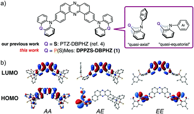
Smart emissive organic materials that exhibit reversible changes in luminescence properties in the solid state in response to external stimuli, such as mechanical forces, temperature, and vapors (i.e., mechanochromic luminescence: MCL), can find diverse applications in security inks, sensors, and optoelectronic devices.1 Two-color-changing MCL systems have been intensively studied over the last decade.1 In sharp contrast, the development of multi-color-changing MCL organic materials has been sluggish, due to the scarcity of design guidelines to meet demanding criteria to form multiple metastable states that must be also interconvertible and emissive in the solid state.2 To address the issue and develop value-added MCL materials, taking into consideration that D–A–D π-conjugated triad scaffolds are widely used in materials science,3 we have recently demonstrated that a twisted donor–acceptor–donor (D–A–D) triad (PTZ–DBPHZ, Fig. 1a) exhibits tricolor-changing MCL properties4 along with efficient thermally activated delayed fluorescence (TADF).5 Most importantly, owing to the conformational flexibility of phenothiazine (PTZ) donors (quasi-equatorial and quasi-axial, Fig. 1a), the D–A–D molecule can adopt multiple metastable conformers, and they are switchable by external stimuli such as grinding, heating, and exposure to vapor. The interconversions among these conformers boost different emissive channels, depending on the charge transfer (CT) nature of the excited states associated with each conformer. To enhance the “conformation-dictated emission regulation” concept, herein we designed a novel twisted D–A–D triad (DPPZS–DBPHZ) 1 that comprises dibenzo[a,j]phenazine (DBPHZ)6 as the A and dihydrophenophosphanizine7 sulfide (DPPZS) as the Ds (Fig. 1a). Notably, the molecule is endowed not only with multi-color-changing MCL but also remarkable acid/base-responsive emission switching, single crystal transition-induced emission change, and room-temperature phosphorescence in a host matrix. The similarity in atomic radius between P (0.98 Å) and S (0.88 Å) would allow the donor (DPPZS) to mimic the flexible conformational change of PTZ–DBPHZ,4 although this replacement would not completely mimic the behavior of PTZ–DBPHZ due to the extra S
![[double bond, length as m-dash]](https://www.rsc.org/images/entities/char_e001.gif) P and Mes-P moieties. Fig. 1b illustrates the optimized structures and the frontier orbitals of possible conformers of 1 calculated by the DFT method at the B3LYP/6-31+G(d,p) level.8
P and Mes-P moieties. Fig. 1b illustrates the optimized structures and the frontier orbitals of possible conformers of 1 calculated by the DFT method at the B3LYP/6-31+G(d,p) level.8
As expected, depending on the conformation, the HOMO/LUMO distributions show significant variations, and this is also the case with the HOMO–LUMO gaps and excitation modes (Fig. S1, ESI†).8 Furthermore, the distinct separation of the HOMOs and LUMOs of the AE and EE conformers implies a small single-triplet splitting (ΔEST) that would be promising for TADF emission.9 Scheme S1 (ESI†) illustrates the synthetic route to 1.8 The double Br–Li permutation of N-Boc bis(o-bromophenyl)amine 2 generated a dilithiated species, which was subsequently trapped with P-Mes dihalophosphine10 to give N-protected dihydrophenophosphanizine 3 in 67% yield. Since P(III) compound 3 was gradually oxidized under air into the corresponding phosphine oxide, it was subsequently converted into 4 by sulfurization with S8 to protect the P center from oxidation. The detachment of the N-Boc group with trifluoroacetic acid (TFA) afforded 5 in 60% yield. The following Pd-catalyzed Hartwig-Buchwald double amination of dibromo DBPHZ 66 with 5 successfully provided the D–A–D compound 1 in good yield.11 The X-ray crystallographic analyses of the single crystals of 4 and 5 grown from n-hexane/AcOEt unambiguously determined their molecular conformations (Fig. S2 and S3, ESI†).12 The central 6-membered heterocycle of 4 takes a boat-chair conformation, with both the N-Boc and P-Mes groups occupying the axial positions of the boat-chair (Fig. S2a, ESI†), which seems to be common for phenophosphanizine compounds.13 The presence of the P![[double bond, length as m-dash]](https://www.rsc.org/images/entities/char_e001.gif) S functionality allows a dimeric structure through complementary C–H⋯S (2.97 Å) contacts (Fig. S2b, ESI†). The central heterocycle of 5 adopts a less-bent structure, and the P-Mes group occupies the equatorial site on the boat-chair (Fig. S3a, ESI†), which might due to the formation of a dimeric structure through complementary N–H⋯S (2.59 Å) contacts (Fig. S3b, ESI†).
S functionality allows a dimeric structure through complementary C–H⋯S (2.97 Å) contacts (Fig. S2b, ESI†). The central heterocycle of 5 adopts a less-bent structure, and the P-Mes group occupies the equatorial site on the boat-chair (Fig. S3a, ESI†), which might due to the formation of a dimeric structure through complementary N–H⋯S (2.59 Å) contacts (Fig. S3b, ESI†).
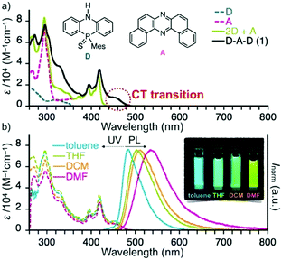
The comparison of UV-vis absorption of diluted dichloromethane (DCM) solutions of D, A, a mixture of D and A (2![[thin space (1/6-em)]](https://www.rsc.org/images/entities/char_2009.gif) :
:![[thin space (1/6-em)]](https://www.rsc.org/images/entities/char_2009.gif) 1 ratio), and D–A–D 1 clearly showed that an absorption observed at around 460 nm for 1 is assignable to an intramolecular charge-transfer (ICT) transition (Fig. 2a). The CT absorption showed a slight bathochromic shift as the solvent polarity increased (Fig. 2b), suggesting the mixing of CT and π–π* natures. The photoluminescence (PL) spectra of 1 exhibited a significant positive solvatochromism as a function of solvent polarity, with moderate photoluminescence quantum yields (PLQYs) ranging from 0.26 to 0.34 (Table S5, ESI†).8 Since there would be significant differences in conformations in solution (all conformers are in equilibrium) and in solid state (specific conformers are dominant, vide infra), it would be difficult to correlate the photophysics of the solutions and solid state at this time.
1 ratio), and D–A–D 1 clearly showed that an absorption observed at around 460 nm for 1 is assignable to an intramolecular charge-transfer (ICT) transition (Fig. 2a). The CT absorption showed a slight bathochromic shift as the solvent polarity increased (Fig. 2b), suggesting the mixing of CT and π–π* natures. The photoluminescence (PL) spectra of 1 exhibited a significant positive solvatochromism as a function of solvent polarity, with moderate photoluminescence quantum yields (PLQYs) ranging from 0.26 to 0.34 (Table S5, ESI†).8 Since there would be significant differences in conformations in solution (all conformers are in equilibrium) and in solid state (specific conformers are dominant, vide infra), it would be difficult to correlate the photophysics of the solutions and solid state at this time.
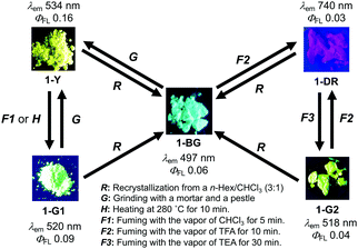
As expected, D–A–D compound 1 showed multi-color-changing MCL properties in the solid state (Fig. 3). Crystals obtained from n-hex/CHCl3 showed blue–green emission (λem 497 nm) upon irradiation with UV light (1-BG, Fig. 3 and Fig. S7, ESI†).8 Grinding of 1-BG (G, Fig. 3) with a pestle and a mortar caused a morphological transition from the crystalline state to an amorphous meta-stable state emitting yellow light (1-Y, Fig. 3), which was clearly suggested by the PXRD and DSC measurements (Fig. S8 and S9, ESI†).8 This morphological transition caused a significant red shift in the emission (1394 cm−1) with an increase in PLQY (Fig. 3). By fuming (F1, Fig. 3) or thermal annealing (H, Fig. 3), the meta-stable solid (1-Y) underwent a phase transition to the more stable crystalline state 1-G1 (Fig. 3 and Fig. S8, S9, ESI†), showing slightly blue-shifted emission (λem 520 nm). Notably, 1-BG exhibited a drastic response toward acid (F2, Fig. 3). Upon treatment with TFA vapor, pale yellow 1-BG immediately turned to pale purple 1-DR, exhibiting near-infrared (NIR) emission in the solid state (λem 740 nm, Fig. S7, ESI†), while treatment of 1-DR with triethylamine (TEA) vapor (F3, Fig. 3) allowed a blue-shift of the emission to bright green (1-G2, λem 518 nm), which is similar to that of 1-G1 (Fig. 3). Notably, these acid–base responsive emission color changes were reversible (F2 and F3, Fig. 3), and were accompanied by a very large Δλem, as large as 222 nm (5791 cm−1). It should be noted that there are few reports on emissive solids that exhibit remarkable stimuli-responsive emission switch between the visible and NIR regions.14 All the solids reverted back to 1-BG through recrystallization (R, Fig. 3).
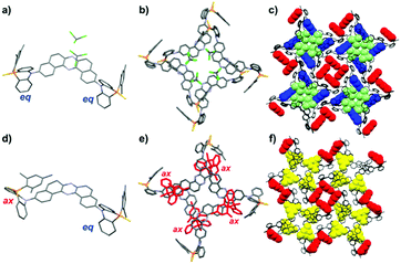
A single crystal (SC) of 1 was obtained by rapidly diffusing a CHCl3 solution of 1 into n-hexane. The X-ray crystallographic analysis revealed that 1 adopts a double quasi-equatorial conformation (EE), holding two CHCl3 molecules per unit (1·CHCl3, Fig. 4a).12 The molecules form ordered micro pores, where CHCl3 are included inside the channel (Fig. 4b and c). Notably, desorption of CHCl3 from 1·CHCl3 under vacuum caused an SC-to-SC transition, allowing for the conformational change in a DPPZS unit from equatorial to axial (1-apo, Fig. 4d). Importantly, the SC-to-SC transition did not cause a significant disturbance of the supramolecular channel structures (Fig. 4e and f). Furthermore, the spaces filled with CHCl3 in 1·CHCl3 were replaced by the P-Mes group on the axial donor in 1-apo crystals (yellow in Fig. 4f). Most importantly, the transition caused a significant change in emission profiles (Fig. S10, ESI†),8 and the PL spectra of 1·CHCl3 and 1-apo are very similar to those of 1-BG and 1-Y, respectively. Since no significant change, other than the molecular conformation of a donor unit (from EE to AE), was observed through the transition, this would be clear evidence for how molecular conformations in the D–A–D scaffold significantly influence its emission properties. In conjunction with these experimental data and the TD-DFT calculations (Fig. S1, ESI†),8 the relationship between the conformations and MCL properties of 1 would be explained as follows: the blue–green emission of 1-BG comes from the EE conformer, while the yellow emission of 1-Y derives from the AE conformer, as clarified with the above-mentioned results; the green emissions of 1-G1 and 1-G2 would be ascribed to the AA conformer or a mixture of AE and AA conformers (vide infra). Since the D–A geometry of the EE conformer is perpendicular, the HOMO–LUMO transition in the EE conformer is basically forbidden (λ 516 nm, f = 0.000, Fig. S1, ESI†).8 Since the electron-donating ability of a DPPZS unit is much weaker than that of PTZ, photo-induced electron transfer to generate CT states is less likely to occur. Instead, the HOMO−6 to LUMO transition is feasible, due to its π–π* nature (λ 390 nm, f = 0.474). On the other hand, in the AE form, a smaller excitation energy is required, which is ascribed to the allowed HOMO−1 to LUMO transition (λ 450 nm, f = 0.364, CT and π–π* hybrid transition), qualitatively rationalizing why the EE conformer showed a higher-energy (bluer) emission than that of the AE conformer. Furthermore, the TD-DFT calculation indicated that the HOMO–LUMO transition is allowed in the AA conformer (λ 444 nm, f = 0.652, π–π* transition), and the excitation energies of AA and AE are very close (Fig. S1, ESI†), implying that the emission spectra of AE and AA would overlap. It should be noted that the relationship between conformers (AA, AE, and EE) and the order of λem for D–A–D compound 1 is different from that for PTZ–DBPHZ,4 where the CT nature of each conformer exclusively governs the λem order (i.e., λem: EE > AE > AA). The discrepancy between PTZ- and DPPZS-installed D–A–D compounds could be ascribed to the difference in electron-donating abilities of the Ds, which determine whether or not the populated locally excited singlet state of the A unit (1LEA) can be converted to more energetically-relaxed charge-transfer states (1CT).9 The influences of the P![[double bond, length as m-dash]](https://www.rsc.org/images/entities/char_e001.gif) S and P-Mes moieties, which might form aggregates in solution and solid state, on their emission properties are not totally excluded.
S and P-Mes moieties, which might form aggregates in solution and solid state, on their emission properties are not totally excluded.
To obtain deeper insights into the photophysical properties of 1, time-resolved luminescence spectroscopic measurements were performed in an inert and non-polar Zeonex® host (Fig. 5). Compound 1 showed emissions mainly in two distinct time regions (Fig. 5a). The first component that decays within the order of nanoseconds is attributed to prompt fluorescence (PF) from the singlet excited state (S1). The PL spectra of Zeonex®-based film with a time delay of 3 ns showed two distinct species: a structured peak in the range 400–450 nm that decays within the first few nanoseconds, and a broad Gaussian peak in the range 450–650 nm that decays over a longer time. These two species can be attributed to the emissions from the 1LEA and 1CT singlet states, respectively. With longer delay times (micro-to-milliseconds), delayed emissions were observed (Fig. 5a). Depending on the experimental temperature, both delayed emissions from S1 and the emissions from T1 were observed on similar millisecond timescales. To differentiate these, spectral inspections were conducted at different temperatures. In all the hosts, an emission from T1 (phosphorescence: PH) was observed at a low temperature (80 K) (blue lines in Fig. 5b), with the T1 energy being 2.41 eV in Zeonex®. At an ambient temperature (320 K), a delayed emission observed between 440 and 530 nm in the Zeonex® was identified as TADF, which was confirmed by the linear dependence of the emission intensity in the millisecond delayed region on laser fluence (Fig. S11, ESI†). Notably, in Zeonex®, a significant PH was observed even at room temperature (i.e., room temperature phosphorescence: RTP) without quenching.15 This makes a nice contrast with our previously reported D–A–D compounds,4,9 which do not exhibit RTP. The temperature-dependent emission behaviour of 1 in a Zeonex® host indicates the presence of an interplay between TADF and RTP processes. From the viewpoint of molecular design, the lower electron-donating ability of DPPZS than those of POZ and PTZ destabilizes the 1CT energy. As the result, the ΔEST (0.30 eV) of 1 is moderately larger than those of our previously reported D–A–D triads.4,9 In addition to the ΔEST value, the host environments would constrain the vibrational and rotational movements of the D–A–D compound, which would inhibit non-radiative channels from T1 and allow the boosting of both radiative (TADF and RTP) pathways.16
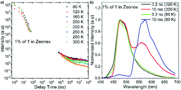 | ||
| Fig. 5 (a) Temperature-variable plots of emission intensity of 1 in Zeonex® (1% w/w) against delay time at different temperatures; (b) normalized PL spectra of 1 in Zeonex® at 320 K and 80 K. | ||
In conclusion, we have developed a novel D–A–D π-conjugated compound that shows unique emission properties beyond multi-color-changing MCL behavior induced by conformational interconversion. The D–A–D compound exhibited a remarkable reversible emission change between the visible and NIR region in response to acid or base. Notably, an analysis of the SC-to-SC transition phenomena provided us with clear evidence for conformation-dependent emission changes in the D–A–D triad. Furthermore, the phosphorus compound unexpectedly exhibited temperature-dependent TADF and RTP emissions in a host matrix. We believe that the results presented here would further guide us to more diverse designs of value-added MCL-materials. Moreover, the photophysical studies shown here would provide us with opportunities for designing metal-free purely organic RTP materials that can be utilized in optoelectronics, such as phosphorescence organic light-emitting diodes (PHOLEDS),17 in the future.
This work was supported by a Grant-in-Aid for Scientific Research on Innovative Areas “π-System Figuration: Control of Electron and Structural Dynamism for Innovative Functions” (JSPS KAKENHI Grant Number JP15H00997 & JP17H05155, to Y. T.), “Coordination Asymmetry” (JSPS KAKENHI Grant Number JP17H05371, to NT), and “Precisely Designed Catalysts with Customized Scaffolding” (JSPS KAKENHI Grant Number JP16H01023 to Y. T. & JP16H01027 to NT), from the MEXT (Ministry of Education, Culture, Science and Technology, Japan), and by the Research Grant from the Japan Prize Foundation and the Continuation Grants for Young Researchers from the Asahi Glass Foundation (to Y. T.). HH acknowledges the EU's Horizon 2020 for funding the PHEBE project under grant agreement No. 641725. P. D. acknowledges the EU's Horizon 2020 for funding the ORZEL project under grant agreement No. 691684. Y. T. and P. D. acknowledge the EU's Horizon 2020 for funding the OCTA project under grant agreement No. 778158. We deeply thank Dr Takashi Tsujimoto and Dr Taro Uematsu (Osaka University) for their assistance for DSC measurements and ICP-AES analysis, respectively.
Conflicts of interest
There are no conflicts to declare.Notes and references
- (a) Y. Sagara and T. Kato, Nat. Chem., 2009, 1, 605–610 CrossRef PubMed; (b) A. Pucci, R. Bizzarri and R. Giacomo, Soft Matter, 2011, 7, 3689–3700 RSC; (c) Z. Chi, X. Zhang, B. Xu, X. Zhou, C. Ma, Y. Zhang, S. Liu and J. Xu, Chem. Soc. Rev., 2012, 41, 3878–3896 RSC; (d) Y. Sagara, S. Yamane, M. Mitani, C. Weder and T. Kato, Adv. Mater., 2016, 28, 1073–1095 CrossRef PubMed; (e) C. Wang and Z. Li, Mater. Chem. Front., 2017, 1, 2174–2194 RSC.
- (a) Y. Sagara and T. Kato, Angew. Chem., Int. Ed., 2011, 50, 9128–9132 CrossRef PubMed; (b) Z. Ma, Z. Wang, M. Teng, Z. Xu and X. Jia, ChemPhysChem, 2015, 16, 1811–1828 CrossRef PubMed and references therein.
- (a) B. J. Eckstein, F. S. Melkonyan, E. F. Manley, S. Fabiano, A. R. Mouat, L. X. Chen, A. Facchetti and T. J. Marks, J. Am. Chem. Soc., 2017, 139, 14356–14359 CrossRef PubMed; (b) T. J. Aldrich, S. M. Swick, F. S. Melkonyan and T. J. Marks, Chem. Mater., 2017, 29, 10294–10298 CrossRef.
- M. Okazaki, Y. Takeda, P. Data, P. Pander, H. Higginbotham, A. P. Monkman and S. Minakata, Chem. Sci., 2017, 8, 2677–2686 RSC.
- (a) H. Uoyama, K. Goushi, K. Shizu, H. Nomura and C. Adachi, Nature, 2012, 492, 234–238 CrossRef PubMed; (b) Y. Tao, K. Yuan, T. Chen, P. Xu, H. Li, R. Chen, C. Zheng, L. Zhang and W. Huang, Adv. Mater., 2014, 26, 7931–7958 CrossRef PubMed; (c) Z. Yang, Z. Mao, Z. Xie, Y. Zhang, S. Liu, J. Zhao, J. Xu, Z. Chi and M. P. Aldred, Chem. Soc. Rev., 2017, 46, 915–1016 RSC; (d) F. B. Dias, T. J. Penfold and A. P. Monkman, Methods Appl. Fluoresc., 2017, 5, 012001 CrossRef PubMed.
- Y. Takeda, M. Okazaki and S. Minakata, Chem. Commun., 2014, 50, 10291–10294 RSC.
- (a) A. I. Bokanov and B. I. Stepanov, Russ. Chem. Rev., 1977, 46, 855–860 CrossRef; (b) L. D. Freedman and H. S. Freeman, Chem. Rev., 1987, 87, 289–306 CrossRef.
- For the details, see the ESI†.
- (a) P. Data, P. Pander, M. Okazaki, Y. Takeda, S. Minakata and A. P. Monkman, Angew. Chem., Int. Ed., 2016, 55, 5739–5744 CrossRef PubMed; (b) D. de Sa Pereira, P. L. dos Santos, J. S. Ward, P. Data, M. Okazaki, Y. Takeda, S. Minakata, M. R. Bryce and A. P. Monkman, Sci. Rep., 2017, 7, 6234 CrossRef PubMed.
- Y. Takeda, T. Nishida and S. Minakata, Chem. – Eur. J., 2014, 20, 10266–10270 CrossRef PubMed.
- Although reduction of the P(V) compound 1 to the corresponding P(III) compound as reference compound using a variety of reductants such as DIBAL, LiAlH4, and P(NMe2)3 was attempted, any reduced P(III) compound was not obtained.
- For a summary of the crystal data of 4, 5, 1·CHCl3, and 1-apo, see the ESI†.
- (a) S. N. Gurkova, A. I. Gusev, V. A. Sharapov, L. A. Yagodina, A. I. Bokanov and B. I. Stepanov, Zh. Strukt. Khim., 1977, 18, 62–66 Search PubMed; (b) A. I. Gusev, S. N. Gurkova, V. K. Bel'skii, V. E. Zavodnik and L. A. Yagodina, J. Struct. Chem., 1980, 20, 537–541 CrossRef.
- (a) Q. Xiao, J. Zheng, M. Li, S.-Z. Zhan, J.-H. Wang and D. Li, Inorg. Chem., 2014, 53, 11604–11615 CrossRef PubMed; (b) M. Tanioka, S. Kamino, A. Muranaka, Y. Ooyama, H. Ota, Y. Shirasaki, J. Horigome, M. Ueda, M. Uchiyama, D. Sawada and S. Enomoto, J. Am. Chem. Soc., 2015, 137, 6436–6439 CrossRef PubMed; (c) T. Seki, N. Tokodai, S. Omagari, T. Nakanishi, Y. Hasegawa, T. Iwasa, T. Taketsugu and H. Ito, J. Am. Chem. Soc., 2017, 139, 6514–6517 CrossRef PubMed.
- S. Mukherjee and P. Thilagar, Chem. Commun., 2015, 51, 10988–11003 RSC.
- J. S. Ward, R. S. Nobuyasu, A. S. Batsanov, P. Data, A. P. Monkman, F. B. Dias and M. R. Bryce, Chem. Commun., 2016, 52, 2612–2615 RSC.
- D. Chaudhuri, E. Sigmund, A. Meyer, L. Rock, P. Klemm, S. Lautenschlager, A. Schmid, S. R. Yost, T. Vanvoorhis, S. Bange, S. Hoger and J. M. Lupton, Angew. Chem., Int. Ed., 2013, 52, 13449–13452 CrossRef PubMed.
Footnote |
| † Electronic supplementary information (ESI) available: Quantum mechanical calculations, synthetic procedures and spectroscopic data of compounds, physicochemical properties, and copies of NMR charts. CCDC 1827226 (4), 1827241 (5), 1829187 (1·CHCl3), and 1830826 (1-apo). For ESI and crystallographic data in CIF or other electronic format see DOI: 10.1039/c8cc02365d |
| This journal is © The Royal Society of Chemistry 2018 |

