Underoil superhydrophilic desert sand layer for efficient gravity-directed water-in-oil emulsions separation with high flux†
Jian
Li
 *ab,
Changcheng
Xu
a,
Changqing
Guo
a,
Haifeng
Tian
a,
Fei
Zha
a and
Lin
Guo
*b
aCollege of Chemistry and Chemical Engineering, Northwest Normal University, Lanzhou 730070, China. E-mail: jianli83@126.com
bKey Laboratory of Bio-Inspired Smart Interfacial Science and Technology of Ministry of Education, School of Chemistry, BeiHang University, Beijing 100191, P. R. China. E-mail: guolin@buaa.edu.cn
First published on 29th November 2017
Abstract
Efficient and rapid separation of emulsified oil/water mixtures is urgently needed and still remains a worldwide challenge. Even though traditional superhydrophobic/superoleophilic filtration membranes have demonstrated to be effective for separation of water-in-oil emulsions, they still suffer from complicated fabrication procedures and lower flux, resulting from their nanoscale pore size. Herein, green desert sands (50 μm to 1 mm) with under-oil superhydrophilicity were introduced, for the first time, to develop into a layer for efficient gravity-directed separation of various water-in-oil emulsions, which could avoid not only sophisticated filtration membranes fabrication process but also the use of expensive low energy materials of fluorosilane involved in traditional superhydrophobic materials. It is worth mentioning that the sand layer could serve as an adsorbent material with under-oil superhydrophilicity, achieving ultrafast gravity-driven separation of tiny water droplets from various water-in-oil emulsions with flux as high as 2342 L m−2 h even though the interspacing between the sand particles is greater than the size of emulsified droplets. Moreover, the sand can be abundantly obtained from deserts, which is another advantage that the current filtrate materials do not possess. In summary, this study provides a general avenue to design under-oil superhydrophilic materials for rapid separation of water-in-oil emulsions. Such an approach can provide some new perspectives for fabrication of novel emulsion-separating materials.
1. Introduction
Efficient, rapid and cost-effective processes for the separation of emulsified oil/water mixtures are highly desirable. However, the development of such processes remains a challenge since emulsified oil/water mixtures always exist in multiple forms, such as surfactant-free and surfactant-stabilized emulsions, oil-in-water and water-in-oil emulsions in various environments.1,2 Moreover, the emulsified oil/water mixtures often contain numerous droplets with size less than 20 μm, which are more difficult to separate than immiscible oil/water mixtures. In the past decades, several traditional techniques such as oil skimmers, centrifuges, coalescers, magnetic separations and flotation technologies have been implemented for separation of immiscible oil/water mixtures.3,4 However, these techniques are not useful for separation of emulsified oil/water mixtures, making further treatment necessary. Currently, development of filtrate materials with super wettability for efficient separation of emulsified oil/water mixtures, has attracted great attention.5–7 In general, these materials are categorized into two types: “water-blocking” and “oil-blocking” materials.8 The “water-blocking” materials always exhibit superhydrophobicity/superoleophilicity and filter or adsorb oil from immiscible oil/water mixtures or emulsions. The “oil-blocking” materials always exhibit superhydrophilicity/underwater superoleophilicity and permit water to quickly pass through, while oil is blocked by the water layer trapped in these materials.9,10 Until now, various oil-blocking or water-blocking materials have been widely fabricated for efficient separation of various emulsions. The oil-blocking materials such as underwater superoleophobic membranes,11–15 porous sponge materials,16–19 bi-functional Janus cotton fabric18 and superhydrophilic foam materials20–22 have been commonly used for efficient separation of oil-in-water emulsions. Water-blocking materials, such as superhydrophobic membranes23–25 or mesh,26–30 superhydrophobic film materials31,32 and sponge-like materials with complex micropores, have also been widely used for separation of water-in-oil emulsions.33,34 Despite achieving great success in separation of emulsified oil/water mixtures in past years, the drawbacks such as lower flux, greater energy consumption and complexity of fabrication processes are major issues that discourage the realization of these materials for large-scale applications. Moreover, the aforementioned drawbacks are essentially resulted from their intrinsic nanoscale pore size. In addition, such smaller pore size is essential for generating the so-called “size-sieving” effect to realize emulsions separation.35 However, the size-sieving separation method is energy consuming as a transmembrane pressure up to several bars is usually required to drive the emulsions to demulsify, and then selectively pass through the membranes.36 Moreover, these materials also suffer from severe decrease in the flux due to surfactant adsorption and/or pore plugging by oil droplets.37 Compared to filtrate materials, the adsorbent materials with high wettability for emulsions disposal possess a unique advantage of avoiding the limitation of smaller nanoscale pore size on flux. To the best of our knowledge, it is still a worldwide challenge for directly adsorbing emulsified droplets from various types of emulsions by the superwetting adsorbent. Recently, a sponge material exhibiting superoleophobicity/superhydrophilicity in air could realize the selective removal of sinking water in oil-rich environments. However, this sponge-like material did not involve adsorption of emulsified water droplets from water-in-oil emulsions.38 In addition, the fabrication process of such materials is rather complicated. Therefore, it is imperative to introduce a facile and low-cost superwetting material to achieve efficient adsorption of emulsified water droplets from various water-in-oil mixtures.Sand is an inorganic natural resource that is available in abundance in the deserts. In addition, the main component of sand is silicon dioxide.39,40 Moreover, sand also contains several metal elements. In general, silicon dioxide and metal particles are covered with a large number of hydroxyl groups, resulting in high surface free energy of these particles. Furthermore, it is their massive hydrophilic compositions with higher surface energy that endows the sand surface with intrinsic water attraction property. Such property of desert sand could be utilized to achieve efficient adsorption of tiny water droplets from various water-in-oil emulsions. To the best of our knowledge, this is the first example of using desert sand for efficient separation of various water-in-oil emulsions with high flux driven solely by gravity. Therefore, the utilization of green, low-cost desert sand to realize efficient separation of various water-in-oil emulsions possesses greater application prospect and laboratory research value.
Herein, we simply cumulated sand particles into a layer, which not only omitted sophisticated film fabrication process but also easily realized the separation of water from water-in-oil emulsions with high flux. The sand layer exhibited excellent underoil superhydrophilicity, which indicated that the sand layer possesses higher water droplets adsorption ability in oil-rich environments. Thus, the sand layer could rapidly capture micron-size water droplets in oil-rich environments to realize both surfactant-stabilized and surfactant-free water-in-oil emulsions separation driven only by gravity, despite the fact that the distance between the sand particles is larger than the size of emulsified droplets. In addition, the separation performances of the sand layer for various water-in-oil emulsions and their internal mechanisms of emulsion separation were carefully investigated. We firmly believe that such natural desert sand layer is a unique tool to realize large-scale separation of various water-in-oil emulsions.
2. Experimental
2.1. Materials
Sand was directly obtained from the local desert. Mineral water bottles, oils, organic solvents and dyes were purchased from a local store. All the oils and organic solvents were of analytical grade and all aqueous solutions were prepared using distilled water.2.2. Preparation of sand layer
First, the dirty sands were thoroughly cleaned in distilled water, and then dried in an oven at 90 °C for 2 h. Subsequently, the sands were randomly dropped onto a mesh surface by gravity and finally fixed by another mesh for preventing the loss of sand particles. The diameter of sand layer surface was 1.5 cm. The density (ρlayer) of the sand layer was calculated using the following equation: ρlayer = mlayer/Vlayer, where, mlayer is the weight of the sand layer, Vlayer is the volume of the sand layer. The density (ρlayer) of the sand layer was calculated to be 2 g cm−3. The porosity (ε) of the sand layer was calculated by the equation: , where, mlayer is the weight of the sand layer, ρsand is the density of sand (ρsand ≈ 2.50 g cm−3), Vlayer is the volume of the layer; εlayer is approximately 79.62%. No other chemical or physical treatments were used prior to the experiments.
2.3. Water-in-oil emulsion separation
The surfactant-stabilized water-in-oil emulsions were prepared by the procedures mentioned below. First, 0.1 g Span 80 was added into four different types of oils (diesel, petroleum ether, kerosene and hexane). Then, water was added dropwise into these oils in a ratio of 1/50 mL/mL with violent agitation. Finally, the mixtures were intensively stirred for more than 6 h until stable milk emulsions were formed. The surfactant-free water-in-oil emulsions without Span 80 were prepared following afore-mentioned procedures. Subsequently, the as-prepared emulsions were poured onto the sand layer and transparent oils were simultaneously collected into a beaker at a constant flux. In addition, the used sand, after simple ethanol treatment, was recycled for further use in the emulsions separation.2.4. Characterizations
The surface morphology of the sand particles was examined by field emission scanning electron microscopy (FE-SEM). The 3D images of sand were recorded by a non-contact 3D surface contour graph (MicroXAM-800, USA). The contact angles (CAs) were measured using a SL200KB apparatus at ambient temperature, and the volumes of probing liquids in the measurements were approximately 5 μL. The water content in the collected oil filter was measured using a Karl Fischer Titrator (SN-WS200A). Optical microscopy images were recorded on an inverted fluorescence microscope IX51 (Olympus, Japan) by pouring the emulsions, before and after separation, on a biological counting board. Dynamic light scattering (DLS) measurements were performed on a Zetasizer Nano ZS (Malvern, UK).3. Results and discussion
Fig. 1 illustrates the preparation process of sand layer and its application in the separation of water-in-oil emulsions. The desert sand was obtained through facial washing, drying procedures, and then, accumulated into a layer onto a stainless steel mesh (300 mesh sizes). Finally, the sand layer was fixed by another identical mesh to prevent the loss of the sand particles. The facile preparation procedure coupled with the low-cost desert sand makes the sand layer a great promise for the large-scale separation of various types of water-in-oil emulsions.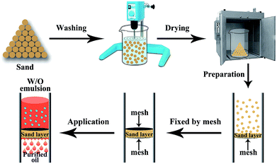 | ||
| Fig. 1 Illustration of the preparation process of sand layer and its application for the separation of water-in-oil emulsions. | ||
The sand used in our experiments was directly obtained from desert. The surface morphologies of the sand were investigated by FE-SEM. Fig. 2a–c shows the FE-SEM images of sand particles at different magnifications. As shown in Fig. 2a, the sand layer consists of numerous sand particles with different shapes and sizes. Moreover, the large interspaces between the sand particles with diameters greater than 30 μm can also be observed (Fig. 2b). Moreover, the surface of the sand particles exhibited a micro-sized rough structure instead of smooth surface, and much of the nanoscale debris is randomly distributed over the surface of the sand particles (Fig. 2c). In addition, the topographical texture of the surface of the sand layer was further characterized by 3D surface contour images. As shown in Fig. 2d, the 3D image demonstrated that the sand particle surface possesses an unevenly raised rough structure.41,42Fig. 2e and f shows the 3D images of sand layer surfaces, and the surface roughness was estimated to be approximately dozens of microns. Therefore, the sand layer consists of numerous sand particles with rough surface structure.
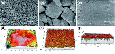 | ||
| Fig. 2 (a–c) FE-SEM images of sand particles with different magnification. 3D images of (d) sand particle surface and (e, f) sand layer surface. | ||
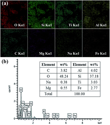
The chemical composition of sand was confirmed by energy-dispersive spectrometry (EDS). The EDS mapping images are presented in Fig. 3a. It can be clearly observed that the sand contains many metals. EDS analysis of sand is shown in Fig. 3b, in which two main peaks corresponding to oxygen and silicon can be observed with the atomic percentage of O and Si being 48.24% and 37.18%, respectively. In addition, the other peaks ascribed to C, Na, Mg, Al, Ti and Fe are also presented in Fig. 3b. Moreover, silicon dioxide and metals usually have a high surface free energy. In addition, it is well-known that sand particles contain numerous –OH groups. These results demonstrated that the desert sand possesses numerous chemical compositions with high surface free energy and large number of hydroxyl groups, which endow the sand surface with intrinsic excellent hydrophilic property.
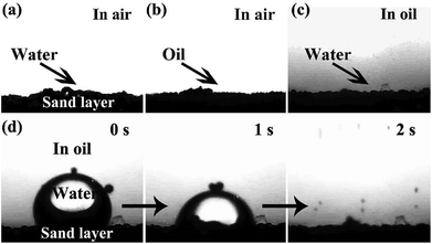
The surface wettability of the sand layer was investigated by a contact angle analyzer. Owing to the high surface free energy and rough surface structure of the sand particles, the sand layer exhibits superhydrophilic and superoleophilic behavior in air as well as under-oil superhydrophilic property. As presented in Fig. 4a and b, when water and oil droplets were dropped onto the sand layer, water was rapidly adsorbed by the sand layer, while the oil droplet quickly spread out on the sand layer; all the obtained contact angle was 0°, indicating superhydrophilicity and superoleophilicity in air. Moreover, the sand layer also exhibited excellent under-oil superhydrophilic behavior. As shown in Fig. 4c, when a water droplet contacted with the sand layer in oil, the water droplet was rapidly caught by sand particles and finally adsorbed by the sand layer (Fig. 4d and Movie S1†), demonstrating under-oil superhydrophilicity. The afore-mentioned special wettability of the sand layer would endow itself superior capture ability toward microsize water droplets in various oil-rich environments.
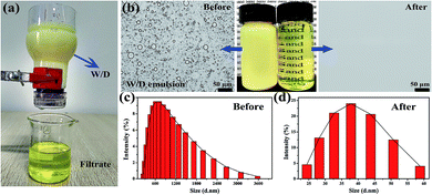
Due to the superior under-oil superhydrophilicity as well as special surface topography of sand particles, the sand layer could rapidly and efficiently separate various types of water-in-oil emulsions. To evaluate the separation capacity of the sand layer for water-in-oil emulsions, a variety of surfactant-stabilized and surfactant-free water-in-oil emulsions including water-in-diesel, water-in-petroleum ether, water-in-kerosene and water-in-hexane emulsions were prepared. As shown in Fig. 5a, the as-prepared emulsions were poured onto the sand layer to allow the water-in-oil emulsions to be separated (driven only by gravity), which can be clearly seen in Movie S2–S5.†Fig. 5b–d displays the separation results of Span 80 stabilized water-in-diesel (W/D) emulsion. In the digital photos (Fig. 5b), it can be observed that the milky Span 80 stabilized water-in-diesel emulsion turned from opaque (left) to transparent (right) after permeating through the sand layer. Moreover, the optical microscope images of the W/D emulsion before and after separation were captured by an inverted fluorescence microscope. As shown in Fig. 5b, densely packed microsize water droplets are detected in the optical images of original water-in-diesel emulsion, while no water droplets were observed in the entire image of the filtrate, which indicates that all tiny water droplets in the emulsions were successfully removed by the sand layer. In addition, the droplet size distributions of the emulsion before and after separation were measured by dynamic light scattering (DLS). As exhibited in Fig. 5c and d, the water-in-diesel emulsion contained water droplets with a broad size distribution ranging from 255 nm to 3580 nm, which is clearly smaller than the interspace between sand particles that are larger than 20 μm (Fig. S1†). In addition, the filtrate exhibited a droplet size distribution ranging from 24.4 nm to 58.8 nm. Moreover, the other Span 80 stabilized water-in-oil emulsions, i.e., water-in-petroleum ether (W/P), water-in-kerosene (W/K) and water-in-hexane (W/H) were also successfully separated and these results can be clearly seen in Fig. S2.† This indicated that the sand layer possesses superior tiny water droplets removal ability from various water-in-oil emulsions.
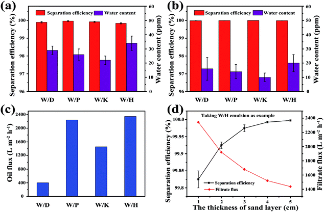
Furthermore, the separation performances of the sand layer for various water-in-oil emulsions were evaluated by measuring the water content in filtrates and corresponding separation efficiencies. The water content was quantitatively measured by Karl Fischer Titrator. In addition the separation efficiency (R) can be calculated by the equation: R = 1 − Cf/Co × 100%, where Cf is the water content in collected filtrate and Co is the water content in original water-in-oil emulsion. As exhibited in Fig. 6a, the separation efficiency of surfactant-stabilized water-in-oil emulsion is up to 99.98%, while the water content in the corresponding filtrate is less than 34 ppm. Moreover, the separation efficiency of surfactant-free water-in-oil emulsions is up to 99.99% and water content in filtrate is less than 20 ppm (Fig. 6b). Moreover, the sand layer also exhibited higher filtrate flux for various water-in-oil emulsions. As shown in Fig. 6c, the filtrate fluxes for W/D emulsion, W/P emulsion, W/K emulsion and W/H emulsion are all around 400 L m−2 h−1, 2241 L m−2 h−1, 1456 L m−2 h−1 and 2342 L m−2 h−1, respectively. The abovementioned filtrate flux was six times larger than that of other filtrate materials directed only by gravity, and still larger than the other filtrate materials driven by external pressure, which are summarized in Table 1. In Fig. 6d, it can be observed that the filtrate flux of water-in-diesel emulsion decreased quasi-exponentially with the increase in the thickness of the sand layer (from 1 cm to 5 cm). In addition, the separation efficiency of water-in-diesel emulsion also increased with increase in the thickness of the sand layer, which was due to a longer effective separation distance (Fig. 6d).
| Materials | Substrate | Method | Wettability | Driver | Flux | Reference |
|---|---|---|---|---|---|---|
| PVDF membrane | Free standing | Phase inversion method | Superhydrophobicity/superoleophilicity | 0.09 MPa | 1125 L m−2 h−1 | 5 |
| SWCNT network film | Free standing | Vacuum filtration method | Hydrophobicity/superoleophilicity | 0.01 MPa | 1587 L m−2 h−1 | 32 |
| Polymer/CNTs hybrid membrane | Carbon nanotube | Covalent attachment | Superhydrophobicity/superoleophilicity | 0.01 MPa | 500 L m−2 h−1 | 28 |
| SBS-SSM filter | Stainless steel mesh | Electrostatic self-assembling & spin coating method | Superhydrophobicity/superoleophilicity | Gravity | — | 23 |
| CNFs-PDMS inlay-gated SSM | Stainless steel mesh | Vacuum filtration method | Superhydrophobicity/superoleophilicity | Gravity | 893 L m−2 h−1 | 25 |
| PPy-coated SSMs | Stainless steel mesh | Electrochemical polymerization | Superhydrophobicity/superoleophobicity | Gravity | 350 L m−2 h−1 | 26 |
| Polydopamine-silica coated membrane | Stainless steel mesh | Chemistry and Stöber method | Superhydrophobicity/superoleophilicity | Gravity | — | 27 |
| Sand layer | Stainless steel mesh | Stacking method | Underoil superhydrophilicity | Gravity | 2342 L m−2 h−1 | This work |
Furthermore, the difference in the flux (J) of various water-in-oil emulsions and the change trend of flux with the thickness of sand layer could be explained by Hagen–Poiseuille equation: J = επrp2Δp/8μL, where, ε is the surface porosity, rp is the pore radius, Δp is the pressure drop, μ is the oil viscosity, and L is the effective filtrate distance.43 Through the analysis of the above formula, we can conclude that the flux is inversely proportional to the viscosity of oils. In addition, the differences in the flux of various emulsions could be observed in Fig. 6c. The flux of W/H and W/P emulsions (5.1 mPa s for diesel, 2.2 mPa s for kerosene) is higher than that of W/D and W/K emulsions (0.3 mPa s for petroleum ether, 0.33 mPa s for hexane). As analyzed above, the filtrate flux of water-in-diesel emulsion is inversely proportional to the effective penetration distance (L). It is worth noting that the water-in-oil emulsions were completely separated only in a single step by simply passing it through the sand layer.
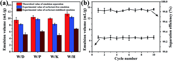
Due to the fact that only a certain amount of water can be adsorbed by the sand layer, the theoretical value (Vg, mL g−1) of separation capacities of various water-in-oil emulsions can be estimated by the equitation:
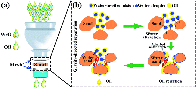
For understanding the separation mechanism of water-in-oil emulsions through the sand layer, the schematic illustration of separation process for water-in-oil emulsions is provided in Fig. 8a. It can be observed that the sand particles were sandwiched between the two meshes in the cap of plastic bottles that act as an adsorption layer, and the as-prepared emulsions were poured onto the sand layer for achieving water-in-oil emulsions separation driven solely by gravity. Moreover, these sand particles in the layer use their selective adsorption ability to harvest tiny water droplets from water-in-oil emulsions. In addition, the details of the separation mechanism of water-in-oil emulsions are illustrated in Fig. 8b. The internal separation mechanism can be depicted as follows: generally, surfaces of high surface energy have stronger affinity to water than oil, while surfaces of low surface energy show stronger affinity to oil.44 It is well-known that the main component of sand is silicon dioxide and sand also contains several metal elements. In addition, its chemical composition with high surface energy and hydroxyl groups endow the sand surface with intrinsic water adsorption ability in oil rich environment as shown in Movie S6.† Thus, the surfaces of sand particles possess a tendency to capture water droplets from surfactant-free water-in-oil emulsions. Driven by the high surface energy, the microsize tiny water droplets were easily extracted from the emulsions as soon as the emulsion touches the surfaces of the sand particles. Subsequently, the purified oils continuously passed through the sand layer via larger-interspaces between the sand particles. Compared with the surfactant-free water-in-oil emulsion, it is difficult for the surfactant-stabilized tiny water droplets in the emulsions to arrive at the surface of the sand particles, which was due to the fact that tiny water droplets and oil were linked by the hydrophilic and hydrophobic particles of the surfactant, respectively. However, the sand surfaces with high surface energy could provide external surface energy to break such forces, resulting in demulsifying the emulsion droplets; subsequently, the exposed tiny water droplets were captured by the sand particles. Furthermore, the water droplets that covered onto the surfaces of sand particles could induce a higher driving force for further capturing tiny water droplets from the water-in-oil emulsions, resulting in more water droplets to rapidly coalesce and aggregate into massive size droplets around the sand particles surfaces.45 Therefore, both surfactant-free and surfactant-stabilized water-in-oil emulsions were separated successfully through the sand particles layer. Exploration of separation mechanism of water-in-oil emulsions on sand particles could be useful in finding novel approaches for ultra-fast gravity-driven separation of various emulsions under the conditions of pore size is greater than that of emulsified droplets.
4. Conclusion
In summary, we have demonstrated the preparation of a green, low-cost desert sand layer through simple washing, drying and stacking procedures. It is worth mentioning that this desert sand layer could serve as an adsorbent material with under-oil superhydrophilicity for efficient gravity-directed separation of various surfactant-stabilized and surfactant-free water-in-oil emulsions with high flux although the interspaces between sand particles are larger than that of emulsified droplets. In particular, this approach can be easily adapted to other under-oil superhydrophilic inorganic materials for rapidly separation of water-in-oil emulsions. Moreover, the sand layer also showed superior recyclability and high separation efficiency for various water-in-oil emulsions separation. In addition, the sand used in such separations can be directly obtained from desert and does not require any chemical or physical treatments. Therefore, utilization of this facile and green sand layer for the separation of various water-in-oil emulsions would offer a new perspective on practically solving the problems of quality deterioration of fuel caused by activities of humankind.Conflicts of interest
There are no conflicts to declare.Acknowledgements
This project was funded by Nature Science Foundation of China (21301141), China Postdoctoral Science Foundation (2017M610031), the Yong Teacher Research Group Foundation of Northwest Normal University (NWNU-LKQN-16-6) and the Guangdong Provincial Key laboratory of New and Renewable Energy Research and Development (No. Y707sc1001).Notes and references
- T. Mason, J. Wilking, K. Meleson, C. Chang and S. Graves, J. Phys.: Condens. Matter, 2006, 18, R635 CrossRef CAS.
- B. Wang, W. Liang, Z. Guo and W. Liu, Chem. Soc. Rev., 2015, 44, 336–361 RSC.
- G. Kwon, A. Kota, Y. Li, A. Sohani, J. Mabry and A. Tuteja, Adv. Mater., 2012, 24, 3666–3671 CrossRef CAS PubMed.
- M. Cheryan and N. Rajagopalan, J. Membr. Sci., 1998, 151, 13–28 CrossRef CAS.
- W. Zhang, Z. Shi, F. Zhang, X. Liu, J. Jin and L. Jiang, Adv. Mater., 2013, 25, 2071–2076 CrossRef CAS PubMed.
- M. Tao, L. Xue, F. Liu and L. Jiang, Adv. Mater., 2014, 26, 2943–2948 CrossRef CAS PubMed.
- J. Fan, Y. Song, S. Wang, J. Meng, G. Yang, X. Guo, L. Feng and L. Jiang, Adv. Funct. Mater., 2015, 25, 5368–5375 CrossRef CAS.
- W. Zhang, N. Liu, Y. Cao, X. Lin, Y. Liu and L. Feng, Adv. Mater. Interfaces, 2017, 4, 1700029 Search PubMed.
- J. Li, D. Li, Y. Yang, J. Li, F. Zha and Z. Lei, Green Chem., 2016, 18, 541–549 RSC.
- J. Li, Z. Zhao, D. Li, H. Tian, F. Zha, H. Feng and L. Guo, Nanoscale, 2017, 9, 13610–13617 RSC.
- T. Yuan, J. Meng, T. Hao, Z. Wang and Y. Zhang, ACS Appl. Mater. Interfaces, 2015, 7, 14896–14904 CAS.
- W. Zhang, Y. Zhu, X. Liu, D. Wang, J. Li, L. Jiang and J. Jin, Angew. Chem., Int. Ed., 2014, 53, 856–860 CrossRef CAS PubMed.
- Z. Wang, X. Jiang, X. Cheng, C. Lau and L. Shao, ACS Appl. Mater. Interfaces, 2015, 7, 534–9545 Search PubMed.
- J. Ge, J. Zhang, F. Wang, Z. Li, J. Yu and B. Ding, J. Mater. Chem. A, 2017, 5, 497–502 CAS.
- L. Zhang, J. Gu, L. Song, L. Chen, Y. Huang and J. Zhang, J. Mater. Chem. A, 2016, 4, 10810–10815 CAS.
- G. Wang, Y. He, H. Wang, L. Zhang, Q. Y. Yu, S. Peng, X. Wu, T. Ren, Z. Zeng and Q. Xue, Green Chem., 2015, 17, 3093–3099 RSC.
- J. Li, C. Xu, Y. Zhang, R. Wang, F. Zha and H. She, J. Mater. Chem. A, 2016, 4, 15546–15553 CAS.
- L. Xu, Y. Chen, N. Liu, W. Zhang, Y. Yang, Y. Cao, X. Lin, Y. Wei and L. Feng, ACS Appl. Mater. Interfaces, 2015, 7, 22264–22271 CAS.
- M. Khosravi and S. Azizian, ACS Appl. Mater. Interfaces, 2015, 7, 25326–25333 CAS.
- Z. Wang, Y. Wang and G. Liu, Angew. Chem., Int. Ed., 2015, 54, 1–5 CrossRef.
- Z. Luo, S. Lyu, Y. Wang and D. Mo, Ind. Eng. Chem. Res., 2017, 56, 699–707 CrossRef CAS.
- Y. Zhang, X. Yang, Z. Wang, J. Long and L. Shao, J. Mater. Chem. A, 2017, 5, 7316–7325 CAS.
- J. Gu, P. Xiao, Y. Huang, J. Zhang and T. Chen, J. Mater. Chem. A, 2015, 3, 4124–4128 CAS.
- X. Lin, M. Choi, J. Heo, H. Jeong, S. Park and J. Hong, ACS Sustainable Chem. Eng., 2017, 5, 3448–3455 CrossRef CAS.
- Y. Li, Z. Zhang, M. Wang, X. Men and Q. Xue, J. Mater. Chem. A, 2017, 5, 5077–5087 CAS.
- Z. Wang, C. Xiao, Z. Wu, Y. Wang, X. Du, W. Kong, D. Pan, G. Guan and X. Hao, J. Mater. Chem. A, 2017, 5, 5895–5904 CAS.
- Y. Cai, D. Chen, N. Li, Q. Xu, H. Li, J. He and J. Lu, J. Mater. Chem. A, 2016, 4, 18815–18821 CAS.
- X. Lin, J. Heo, H. Jeong, M. Choi, M. Chang and J. Hong, J. Mater. Chem. A, 2016, 4, 17970–17980 CAS.
- M. Liu, Y. Hou, J. Li and Z. Guo, Langmuir, 2017, 33, 3702–3710 CrossRef CAS PubMed.
- Y. Cao, Y. Chen, N. Liu, X. Lin, L. Feng and Y. Wei, J. Mater. Chem. A, 2014, 2, 20439–20443 CAS.
- J. Gu, P. Xiao, J. Chen, F. Liu, Y. Huang, G. Li, J. Zhang and T. Chen, J. Mater. Chem. A, 2014, 2, 15268–15272 CAS.
- W. Zhang, N. Liu, Y. Cao, Y. Chen, L. Xu, X. Lin and L. Feng, Adv. Mater., 2015, 27, 7349–7355 CrossRef CAS PubMed.
- J. Yun, F. Khan and S. Baik, ACS Appl. Mater. Interfaces, 2017, 9, 16694–16703 CAS.
- Y. Si, Q. Fu, X. Wang, J. Zhu, J. Yu, G. Sun and B. Ding, ACS Nano, 2015, 9, 3791–3799 CrossRef CAS PubMed.
- Z. Shi, W. Zhang, F. Zhang, X. Liu, D. Wang, J. Jin and L. Jiang, Adv. Mater., 2013, 25, 2422–2427 CrossRef CAS PubMed.
- W. Zhang, Y. Zhu, X. Liu, D. Wang, J. Li, L. Jiang and J. Jin, Angew. Chem., Int. Ed., 2014, 53, 856–860 CrossRef CAS PubMed.
- B. Al-anzi and O. Siang, RSC Adv., 2017, 7, 20981–20994 RSC.
- Z. Xu, Y. Zhao, H. Wang, X. Wang and T. Lin, Angew. Chem., Int. Ed., 2015, 54, 4527–4530 CrossRef CAS PubMed.
- J. Yong, F. Chen, Q. Yang, H. Bian, G. Du, C. Shan, J. Huo, Y. Fang and X. Hou, Adv. Mater. Interfaces, 2016, 3, 1500650–1500656 CrossRef.
- L. Chen, Y. Si, Z. Guo and W. Liu, J. Mater. Chem. A, 2017, 5, 6416–6423 CAS.
- T. Norgaard and M. Dacke, Front. Zool., 2010, 7, 23 CrossRef PubMed.
- A. Parker and C. Lawrence, Nature, 2001, 414, 33–34 CrossRef CAS PubMed.
- X. Peng, J. Jin, Y. Nakamura, T. Ohno and I. Ichinose, Nat. Nanotechnol., 2009, 4, 353–357 CrossRef CAS PubMed.
- G. Liu, M. Cai, X. Wang, F. Zhou and W. Liu, ACS Appl. Mater. Interfaces, 2014, 6, 11625–11632 CAS.
- X. Zeng, L. Qian, X. Yuan, C. Zhou, Z. Li, J. Cheng, S. Xu, S. Wang, P. Pi and X. Wen, ACS Nano, 2017, 11, 760–769 CrossRef CAS PubMed.
Footnote |
| † Electronic supplementary information (ESI) available. See DOI: 10.1039/c7ta08076j |
| This journal is © The Royal Society of Chemistry 2018 |

