A novel dual phase membrane 40 wt% Nd0.6Sr0.4CoO3−δ–60 wt% Ce0.9Nd0.1O2−δ: design, synthesis and properties†
Yuan
He
a,
Lei
Shi
a,
Fan
Wu
b,
Weiwei
Xie
 c,
Shu
Wang
a,
Dong
Yan
a,
Peijiang
Liu
a,
Man-Rong
Li
 d,
Jürgen
Caro
*e and
Huixia
Luo
 *ae
*ae
aSchool of Materials Science and Engineering, Key Laboratory for Polymeric Composite and Functional Materials of Ministry of Education, Sun Yat-Sen University, No. 135, Xingang Xi Road, Guangzhou, 510275, P. R. China. E-mail: luohx7@mail.sysu.edu.cn
bHarvard John A. Paulson School of Engineering and Applied Sciences, Harvard University, 410 Gordon McKay Laboratory of Applied Science, 9 Oxford St., Cambridge, MA 02138, USA
cDepartment of Chemistry, Louisiana State University, Baton Rouge, Louisiana 70803-1804, USA
dMOE Key Laboratory of Bioinorganic and Synthetic Chemistry, School of Chemistry, Sun Yat-Sen University, No. 135, Xingang Xi Road, Guangzhou, 510275, P. R. China
eInstitute of Physical Chemistry and Electrochemistry, Leibniz University of Hannover, Callinstr. 3A, D-30167 Hannover, Germany. E-mail: juergen.caro@pci.uni-hannover.de
First published on 30th October 2017
Abstract
Oxygen permeation, stability and chemical bonding characteristics of 40 wt% Nd0.6Sr0.4CoO3−δ–60 wt% Ce0.9Nd0.1O2−δ (40NSCO–60CNO) dual-phase composite membrane reactors were investigated. The 40NSCO–60CNO oxygen permeable membrane was prepared via an in situ one-pot one-step EDTA–citric acid method. The crystal structure of the 40NSCO–60CNO dual phase material was characterized by X-ray diffraction (XRD) and in situ XRD. The microstructure was investigated using transmission electron microscopy (SEM) and high resolution transmission electron microscopy (HRTEM) combined with energy-dispersive X-ray spectroscopy (EDXS) and electron energy-loss spectroscopy (EELS). The results show that the 40NSCO–60CNO composite represents a micro-scale mixture of only the two pure phases NSCO and CNO. The oxygen permeation fluxes through the 40NSCO–60CNO dual phase membrane were measured at elevated temperatures (900–1000 °C) with one side of it exposed to synthetic air and the other side to a flowing He gas stream. A stable oxygen permeation rate of 0.90 mL cm−2 min−1 was obtained with a 0.4 mm thick membrane under an air/He oxygen partial pressure gradient at 1000 °C. The 40NSCO–60CNO dual phase membrane with a thickness of 0.6 mm showed a stable oxygen flux of 0.55 mL cm−2 min−1 at 950 °C for 100 h under pure CO2 sweeping.
Introduction
Mixed ionic–electronic conducting oxygen transport materials (OTMs) have attracted much attention as a cost-efficient replacement for traditional cryogenic air separation units due to their high promise in oxygen supply1–4 to power stations for CO2 capture according to the oxyfuel concept.5–8 Oxygen can be separated from oxygen-containing atmospheres via OTMs by using a portion of the exhaust gas CO2 as a sweep gas, which can reduce the costs by 35% and save 60% of the energy compared to the conventional cryogenic process.9 In this oxyfuel process, a part of the exhaust gas CO2 is sequestrated while the other portion is recycled and used as a sweep gas for oxygen separation through OTMs. Thus, high oxygen permeability and good structural stability in the presence of high concentrations of CO2 are among the fundamental requirements for OTMs for CO2 capture in the oxyfuel process. Due to this oxyfuel concept for CO2 capture, as a cost-efficient replacement for traditional cryogenic air separation units, studies of CO2-stable OTMs with high oxygen permeability have recently increased in number.Depending on the number of phase compositions, OTMs generally can be divided into two types: single-phase and two-phase oxygen transport membrane materials. Single perovskite-type oxygen permeable materials with the general formula of ABO3 have been extensively studied over the last two decades due to their high oxygen permeability and low cost (see ref. 10–12, for example). Although great efforts have been focused on the development of single perovskite-type OTMs, many problems still hinder their practical applications, such as low mechanical strength, poor chemical stability, and unsatisfactory long-term stability.13,14 Especially, alkaline-earth containing single perovskite-type oxygen permeable materials are susceptible to CO2 contamination from air or react with CO2 and form carbonates in a CO2 atmosphere.15,16
Dual phase-type membranes, which consist of an oxygen ionic/protonic conducting (OIC/PC) phase and an electronic conducting (EC) phase in a micro-scale phase mixture, are considered to be possible alternatives to single perovskite-type membranes due to their compositions that can be tailored according to practical requirements.2,3,17–26,30 In our group, we have developed some new CO2-stable dual phase oxygen permeable membrane materials, such as NiFe2O4−δ–Ce0.9Gd0.1O2−δ(NFO–CGO),5,20 Mn1.5Co1.5O4−δ–Ce0.9Pr0.1O2−δ(MCO–CPO),8 Fe2O3–Ce0.9Gd0.1O2−δ(FO–CGO),21 Sm0.5Sr0.5Cu0.2Fe0.8O3−δ–Ce0.8Sm0.2O−δ(SSCFO–CSO),22 Pr0.6Sr0.4FeO3−δ–Ce0.9Pr0.1O2−δ(PSFO–CPO),6 and Nd0.6Sr0.4FeO3−δ–Ce0.9Nd0.1O2−δ(NSFO–CNO).23 The aforementioned dual phase membranes show high CO2 stability; however, the low oxygen permeability of most of them needs to be improved to meet the industrial application requirements. Therefore, it is highly desired to develop novel OTMs with high oxygen permeability and stability under real application conditions.
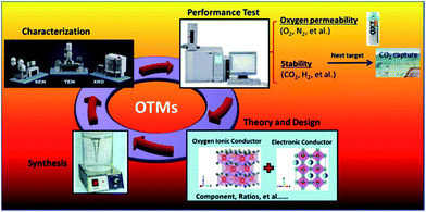
Here we report the development of a novel noble-metal free dual phase membrane material, 40 wt% Nd0.6Sr0.4CoO3−δ–60 wt% Ce0.9Nd0.1O2−δ (40NSCO–60CNO). We selected this 40–60 composition to ensure that it can achieve a threshold above both the EC (mainly NSCO) and the OIC percolation (CNO) thresholds.27–30 The 40NSCO–60CNO dual phase membrane was prepared via an in situ one-pot one-step EDTA–citric method. In this dual phase system, CNO is the main phase for ionic transport, and NSCO is the main phase for electronic transport, which also assists the ionic transport. The phase structure and stability, as well as oxygen permeability, were investigated under different atmospheres at high temperatures. Fig. 1 shows the flowchart of the main work in this paper.
Experimental
Preparation of powders and membranes
The 40NSCO–60CNO dual phase powder mixture was synthesized via an in situ one-pot one-step EDTA–citric acid method.20,23 The appropriate stoichiometric metal nitrates Sr(NO3)2, Co(NO3)2, Ce(NO3)3 and Nd(NO3)3 in an aqueous solution were mixed in a beaker. After stirring the metal nitrate solutions for 20 min, calculated amounts of citrate and EDTA were added and the pH value was adjusted to ∼9 by using ammonia. The molar ratio of citric acid![[thin space (1/6-em)]](https://www.rsc.org/images/entities/char_2009.gif) :
:![[thin space (1/6-em)]](https://www.rsc.org/images/entities/char_2009.gif) EDTA
EDTA![[thin space (1/6-em)]](https://www.rsc.org/images/entities/char_2009.gif) :
:![[thin space (1/6-em)]](https://www.rsc.org/images/entities/char_2009.gif) total metal ions was 1.5
total metal ions was 1.5![[thin space (1/6-em)]](https://www.rsc.org/images/entities/char_2009.gif) :
:![[thin space (1/6-em)]](https://www.rsc.org/images/entities/char_2009.gif) 1
1![[thin space (1/6-em)]](https://www.rsc.org/images/entities/char_2009.gif) :
:![[thin space (1/6-em)]](https://www.rsc.org/images/entities/char_2009.gif) 1. Then the solutions were stirred while being heated to 150 °C until the water was evaporated and a gel was formed. The gels were calcined in air at 600 °C in a furnace to remove the organic compounds by combustion, and the primary powders were obtained. These powders were calcined at 950 °C for 10 h in air. The 40NSCO–60CNO powders were pressed to disk membranes under a pressure of 5 MPa in a stainless steel module with a diameter of 18 mm to get green disk membranes. These green disks were pressure-less sintered at 1225 °C in air for 5 h. The surfaces of the disks were carefully polished to 0.60 mm thickness by using 1200 grit-sand paper (average particle diameter 15.3 μm), and then the membranes were washed with ethanol.
1. Then the solutions were stirred while being heated to 150 °C until the water was evaporated and a gel was formed. The gels were calcined in air at 600 °C in a furnace to remove the organic compounds by combustion, and the primary powders were obtained. These powders were calcined at 950 °C for 10 h in air. The 40NSCO–60CNO powders were pressed to disk membranes under a pressure of 5 MPa in a stainless steel module with a diameter of 18 mm to get green disk membranes. These green disks were pressure-less sintered at 1225 °C in air for 5 h. The surfaces of the disks were carefully polished to 0.60 mm thickness by using 1200 grit-sand paper (average particle diameter 15.3 μm), and then the membranes were washed with ethanol.
Characterization of membranes
The phase structure of the as-prepared 40NSCO–60CNO powder and the sintered disk membranes before and after oxygen permeation as well as after the heat treatment in Ar (99.999%) was characterized with X-ray diffraction (XRD, Bruker-D8 ADVANCE and Rigaku RINT2200, Cu Kα radiation). The disc membranes were studied by scanning electron microscopy (SEM) using a JEOL JSM-6700F at an excitation voltage of 20 keV. The elemental distribution in the grains of the fresh dual phase membranes under study was investigated on the same electron microscope by energy dispersive X-ray spectroscopy (EDXS). The as-prepared 40NSCO–60CNO powder and dual phase membrane after being crushed into powder was investigated by using an Oxford Instruments INCA-300 EDX spectrometer with an ultra-thin window at an excitation voltage of 20 keV. For TEM sample preparation, the powders were sonicated in ethanol solution and dropped onto the TEM copper grid. STEM, high resolution TEM (HRTEM), electron energy-loss spectroscopy (EELS), and EDXS techniques were used to study the phase structure, elemental distribution and morphology of the dual phase mixture powder calcined at 950 °C for 10 h in air and the crushed disc membranes after sintering at 1225 °C for 5 h. All these analyses (STEM, TEM, EELS, and EDXS) were performed on a JEOL 2010F with an accelerating voltage of beam energy of 200 keV at room temperature.Oxygen permeability of membranes
The oxygen permeability was studied using a home-made high-temperature oxygen permeation device, which is described in a previous paper.31 The disc membranes were sealed onto a quartz tube at 950 °C for 5 hours with a gold paste (Heraeus, Germany), and the side wall of the membrane disc was also covered with the gold paste to avoid any radial contribution to the oxygen permeation flux. The effective areas of the membranes for oxygen permeation were 0.785 cm2. Air as the feed gas was fed into one side of the membrane, and He or CO2 as the sweep gas was fed into the other side of the membrane. All the inlet gas flow rates were controlled by gas mass flow controllers (Bronkhorst, Germany) and all flow rates were regularly calibrated by using a bubble flow meter. Synthetic air (20% O2 and 80% N2) with a flow rate of 150 cm3 min−1 was the feed; a mixture of He or CO2 (49 cm3 min−1) and Ne (1 cm3 min−1) as the internal standard gas was fed to the sweep side. An Agilent 7890A gas chromatograph with a Carboxen 1000 column was employed to analyze the gas mixture.Chemical bonding analysis
Chemical bonding analysis of Ce0.9Nd0.1O2−δ, Nd0.6Sr0.4CoO3−δ and Nd0.6Sr0.4FeO3−δ structures was performed by Crystal Orbital Hamilton Population (COHP)32 using the Tight-Binding, Linear Muffin Tin Orbital Atomic Sphere Approximation (TB-LMTO-ASA).33 Exchange and correlation were treated by the local density approximation (LDA). The space was filled with overlapping Wigner–Seitz (WS) spheres by the ASA method. Empty spheres were necessary to achieve the LMTO volume criterion, and the overlap of WS spheres was limited to no larger than 22%. The basis set for the calculations included the following wave functions: Ce 6s, 6p, 5d; Nd 6s, 6p, 5d; Fe 4s, 4p, 3d; Fe 4s, 4p, 3d; and O 2s, 2p. The convergence criterion was set to 0.5 meV. A mesh of 20–45 k points in the irreducible wedge of the first Brillouin zone was used to obtain all integrated values, including the density of states (DOS) and crystal orbital Hamiltonian population (COHP) curves.Results and discussion
Characterization of the 40NSCO–60CNO dual phase materials
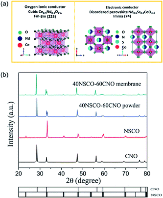
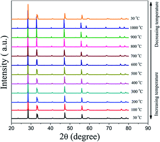
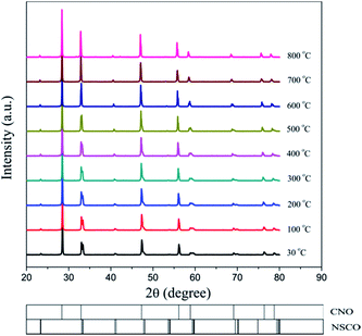
Powder XRD was used to characterize the crystalline structures of the 40NSCO–60CNO dual-phase materials in air. Fig. 2 presents the crystal structures and XRD patterns of the as-obtained 40NSCO–60CNO mixture powders calcined at 950 °C for 10 h in air and the 40NSCO–60CNO dual phase membrane sintered at 1225 °C for 5 h in air. The reference XRD patterns of the pure phase NSCO and CNO, which were synthesized by the in situ one-pot one-step EDTA–citric acid method, are also shown for comparison. From the XRD patterns, it can be seen that the dual phase system merely consists of cubic fluorite structured CNO (ICSD collection code 186665: space group Fm3m, no. 225)34 and an orthorhombic distorted perovskite structure (ICSD collection code 181427: space group Imma, no. 74).35 No additional phases could be detected within the resolution limit of XRD, indicating sufficient mutual stability between CNO and NSCO.In order to determine the phase stability of the 40NSCO–60CNO dual phase membrane material in air, in situ XRD measurements were performed on the 40NSCO–60CNO dual phase membrane. Fig. 3 shows the in situ XRD patterns of the sintered 40NSCO–60CNO dual phase membrane after being crushed into powder, collected in air with increasing temperature from 30 to 1000 °C. During heating and cooling, the 40NSCO–60CNO powder maintained the same crystal structure, suggesting that the 40NSCO–60CNO possesses good phase stability in air atmosphere under experimental conditions. To further check the structural stability of the 40NSCO–60CNO at reduced oxygen partial pressure, the powder of the 40NSCO–60CNO was exposed to a pure Ar atmosphere at different temperatures for 48 h. Fig. 1S† presents the XRD patterns of the 40NSCO–60CNO powder before and after treatment with Ar at different temperatures for 48 h. The crystal structure of the 40NSCO–60CNO remains unchanged even under a pure Ar atmosphere and no change in the phase composition was detected by XRD, which demonstrated that the 40NSCO–60CNO exhibits an excellent structural stability under Ar. Furthermore, Fig. 4 presents the in situ XRD patterns of the sintered 40NSCO–60CNO dual phase membrane after being crushed into powder, collected in 50 vol% CO2 and 50 vol% N2 with increasing temperature from 30 to 800 °C. During heating, the crystal structure of the composite remained unaltered, and no peaks of carbonate were detected, suggesting that the 40NSCO–60CNO possesses good structural stability under a CO2 atmosphere under experimental conditions.
The feasibility of the fabrication of the dual-phase membrane material was then examined by SEM-EDXS, STEM, and EELS. Fig. 5 presents the SEM and EDXS pictures of the as-prepared unpolished 40NSCO–60CNO dual phase membranes after sintering at 1225 °C for 5 h in air at two different magnifications. SEM observations (Fig. 5a–d) revealed that the micro-sized grains are packed closely; no major cracks are visible. In the bulk material, only a few non-connected pores were observed. The NSCO and CNO grains could be distinguished by EDXS (Fig. 5e and f). The same information is provided by EDXS (Fig. 5e and f), which suggests that the green color in the EDXS is an overlap of the Nd, Co and Sr signals, whereas the yellow color (light) stems from an average of the Ce and Nd signals. The mean grain size areas of CNO are larger than that of NSCO. Furthermore, the analysis of the phase composition was performed in STEM mode by EDXS and EELS. Fig. 6a and 7a show parts of STEM elemental mapping images of the 40NSCO–60CNO powder after being calcined at 950 °C for 10 h in air and the sintered 40NSCO–60CNO dual phase membrane after being crushed into powder, respectively. The corresponding EELSs in the energy-loss range of 750–1100 eV are shown in Fig. 6b and 7b. No intermixing of cations between the two phases can be observed (that is, CNO contains neither Sr nor Co, and NSCO contains neither Ce nor Nd), which shows that a dual-phase membrane with well separated grains was obtained by the direct one-pot method. The 40NSCO–60CNO dual phase membrane material was further examined by conducting surface mapping of different elements to provide a clearer picture of the elemental distribution within the dual phase membrane materials. The corresponding elemental mapping images for Ce, Nd, Sr and Co are presented in Fig. 6c–f and 7c–f. According to the Ce, Nd, Co and Sr maps, NSCO and CNO grains are homogeneously distributed without any agglomeration of one phase, indicating no significant reaction between the grains or the formation of grain boundary layers. To obtain more information on the phase composition, HR-TEM was conducted. By this method, different phases can be distinguished. By HR-TEM imaging of the grain boundary between a NSCO and a CNO grain, the characteristic (111) CNO and (021) NSCO in the 40NSCO–60CNO powder after being calcined at 950 °C for 10 h in air (Fig. 6g), and (100) CNO and (220) NSCO planes in the sintered 40NSCO–60CNO dual phase membrane after being crushed into powder (Fig. 7g) were identified on each side of the grain boundary. The presence of new phases could not be detected along the grain boundary. Fig. 2S† shows the fast Fourier transform images of different selected areas in the 40NSCO–60CNO powder after being calcined at 950 °C for 10 h in air. The top one shows the [021] zone axis pattern (ZAP) of Nd0.6Sr0.4CoO3, which has an orthorhombic structure. The bottom one shows the [110] zone axis pattern (ZAP) of Ce0.9Nd0.1O2, which has a cubic structure. Moreover, Fig. 3S† presents the fast Fourier transform images of different selected areas in the 40NSCO–60CNO membrane after being sintered at 1225 °C for 5 h in air after being crushed. The top one shows the [100] zone axis pattern (ZAP) of Ce0.9Nd0.1O2, which has a cubic structure. The bottom one shows the [001] zone axis pattern (ZAP) of Nd0.6Sr0.4CoO3, which has an orthorhombic structure. These results further confirmed that the 40NSCO–60CNO dual phase membrane contains NSCO and CNO grains.
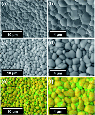 | ||
| Fig. 5 SEM (a–d) and EDXS (e and f) images of the 40NSCO–60CNO membrane after being sintered at 1225 °C for 5 h in air before polishing (see Fig. 2). For the EDXS mapping in Fig. 3e and f, superimpositions of the Nd Lα, Sr Kα and Co Kα (green) and Nd Lα and Ce Lα (yellow) have been used. | ||
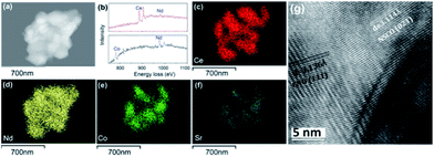 | ||
| Fig. 6 STEM (a), EELS (b), EDXS (c–f) and HRTEM (g) images of the 40NSCO–60CNO powder after being calcined at 950 °C for 10 h in air. | ||
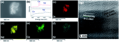 | ||
| Fig. 7 STEM (a), EELS (b), EDXS (c–f) and HRTEM (g) images of the 40NSCO–60CNO membrane after being sintered at 1225 °C for 5 h in air after being crushed. | ||
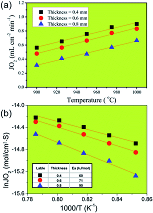
In order to identify the rate-limiting step of oxygen permeation of oxygen transport through our 40NSCO–60CNO membrane, we studied the oxygen permeation through 40NSCO–60CNO membranes with a different thickness at different temperatures. Fig. 8a displays the influence of the different thickness on oxygen permeation on the 40NSCO–60CNO membrane at different temperatures. As expected, the oxygen permeation fluxes of all 40NSCO–60CNO membranes increase with increasing temperature according to the Wagner equation.36,37E.g. for the membrane with a thickness of 0.4 mm, when the temperature increases from 900 to 1000 °C, the oxygen permeation flux increases from 0.56 to 0.90 mL cm−2 min−1. Fig. 8b shows the gas permeation fluxes through the 40NSCO–60CNO dual phase membrane with pure He as the sweep gas as the Arrhenius plot. The apparent activation energies of the 40NSCO–60CNO membrane with a thickness of 0.4, 0.6, and 0.8 mm were calculated to be 60, 71, and 91 kJ mol−1 in the temperature range of 900–1000 °C, respectively.
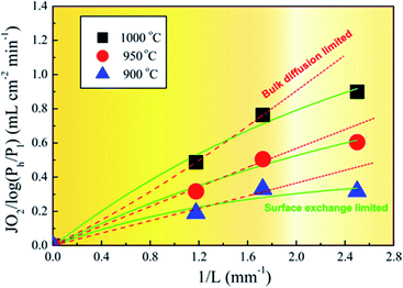
To understand the oxygen migration mechanism related to the membrane thickness, the oxygen permeation flux through the 40NSCO–60CNO dual phase membrane as a function of the reciprocal of the thickness at 900, 950, and 1000 °C, respectively, is plotted in Fig. 9. The oxygen permeation flux increases linearly with the reciprocal of membrane thickness in the thickness range > 0.4 mm, while it shows an increasing curve trend on further decreasing the thickness. This can be described in the Wagner equation:36,37
 | (1) |
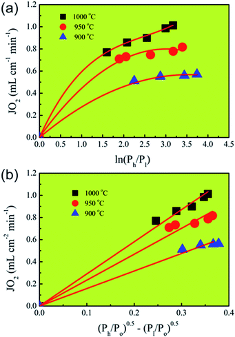
To further confirm the rate-limiting step of oxygen permeation of the 0.4 mm thick dense 40NSCO–60CNO membrane, we studied the oxygen permeation at different temperatures. The oxygen pressure on the air side was kept at a constant value of 0.20 bar. The different oxygen partial pressures on the sweep side were measured by gas chromatography in this study. Following Jacobson A. J et al.,38–40JO2 shows a linear relationship with (Ph − Po)0.5 − (Pl − Po)0.5 according to
 | (2) |
 | (3) |
Correlating and evaluating our oxygen permeation data according to the above theory of Jacobson A. J et al.,38–40 we can state that the values of oxygen permeation fluxes JO2 are a linear function of (Ph/Po)0.5 − (Pl/Po)0.5 and not of ln(Ph/Pl) as shown in Fig. 10. From this finding, it follows that the oxygen permeation through the 40NSCO–60CNO dual phase membrane of 0.4 mm thickness is mainly controlled by the surface exchange reaction rather than by bulk diffusion in the temperature region studied.
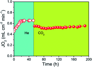
The oxygen permeation flux through the 40NSCO–60CNO dual phase composite membrane with He or CO2 as the sweep gas is shown in Fig. 11 as a function of time. There is an initialization stage of the oxygen flux observed in the 40NSCO–60CNO membrane with He sweep gas. A lot similar results on the initialization stage of the oxygen flux observed in the dual phase OMTs in detail have been reported,41–45 which is considered to be attributed to surface exchange effects. When the oxygen flux reached a stable stage with an oxygen permeation flux of about 0.65 mL cm−2 min−1, the sweep gas was switched to pure CO2. By switching the sweep gas to CO2, the permeation fluxes of the 40NSCO–60CNO dual phase membrane slightly decreased. However, during the whole oxygen permeation test under a pure CO2 atmosphere, an oxygen permeation flux of about 0.55 mL cm−2 min−1 was obtained at 950 °C and no decrease was found. This behavior was also observed in the previous studies of a CO2-stable dual phase membrane which is ascribed to the slight inhibition effect of CO2 on the oxygen surface-exchange.5,6,8 This behavior is different to those of alkaline-earth metal containing single perovskite membranes,15 and some previously reported dual phase membranes. E.g. Kharton et al. have reported that obvious time-dependent degradation of the oxygen permeation flux through a Ce0.8Gd0.2O2−δ–La0.7Sr0.3MnO3−δ dual phase composite membrane was observed due to the formation of Sr(Ce, Ln)O3−δ (Ln is Gd, La) in the grain boundaries, which can block the ionic transport.40
More recently, Kaveh Partovi et al. have reported that the oxygen permeation flux through the 40% Sm0.3Sr0.7Cu0.2Fe0.8O3−δ −60% Ce0.8Sm0.2O2−δ dual phase membrane decreased with increasing time under pure CO2 as the sweep gas at 950 °C due to the formation of alkaline-earth carbonates.18 From the stable oxygen permeation fluxes on our 40NSCO–60CNO, we can exclude chemical reactions between the two NSCO and CNO phases and the formation of alkaline-earth carbonates under CO2 atmospheres involved. Fig. 12 shows that the XRD patterns of the fresh and spent 40NSCO–60CNO dual phase membrane in the long term oxygen permeation measurements with pure CO2 as the sweep gas are identical, indicating that the dual phase membrane displays a high CO2 stability.
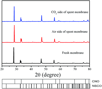 | ||
| Fig. 12 XRD patterns of the fresh and spent 40NSCO–60CNO dual phase membrane in the long term oxygen permeation measurements with pure CO2 as the sweep gas. | ||
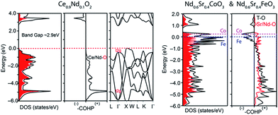
Fig. 13 summarizes the oxygen permeation fluxes through several types of dual phase membranes, where the oxygen permeation flux through our 40NSCO–60CNO membrane is comparable with or even higher than those of other dual phase-type membranes reported in the open literature.5,6,8,20,21,23E.g. the 40 wt% Nd0.6Sr0.4FeO3−δ–60 wt% Ce0.9Nd0.1O2−δ (40NSFO–60CNO) dual phase membrane with a thickness of 0.6 mm exhibits an oxygen permeation flux of 0.21 mL cm−2 min−1 under an air/CO2 oxygen partial pressure gradient at 950 °C,21 which is nearly two times lower than that of our 40NSCO–60CNO membrane. To further investigate the oxygen vacancies in different oxygen permeation membranes, the electronic structure calculations, in particular, the comparison of chemical bonding analysis for 40NSCO–60CNO and 40NSFO–60CNO were conducted. The oxygen ion conductor Ce0.9Nd0.1O2−δ was calculated to be a semiconductor with a band gap of 2.9 eV (see Fig. 14a), which is consistent with a previous report.23 During the calculation for the mixed conductors NSFO and NSCO, in the valence orbital region of the electronic DOS curve for the hypothetical model “NdFeO3”, as shown in Fig. 14b, there are two distinct regions separated by the direct gap in the DOS: (i) below, show mostly O 2p bands mixed with Fe 4s and 3d and Nd 6s/5d valence orbitals; and (ii) above, which contains mostly O 2p bands and Nd 6s and 5d character. A clear band gap at 0.5 eV above the Fermi energy (EF) would suggest NdFeO3 to be an insulator. By adjusting the valence electrons, we approach the Fermi levels for NSFO and NSCO marked in blue and pink separately in Fig. 12b. In line with the chemical valence argument, the Fe/Co–O and Nd/Sr–O COHP curves indicate the orbital interactions in “NSFO” and “NSCO”. Based on the chemical bonding analysis, it can be easily found that the Co–O interaction is located on the maximum antibonding part in the –COHP, which indicates the instability of Co–O interactions. This instability makes it highly possible to produce more oxygen vacancies to lower the Fermi level and reduce the Co–O antibonding interactions, which account for the much higher oxygen permeation flux for 40NSCO–60CNO compared to that of 40NSFO–60CNO.
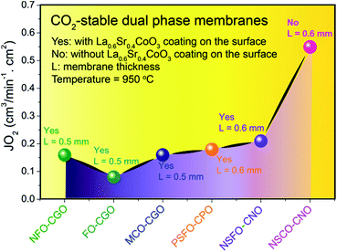 | ||
| Fig. 13 Steady-state oxygen permeation flux (JO2) though different dual phase membranes in disk geometries. | ||
Conclusions
In dual phase membranes, an electron conductor and an ionic (oxygen ions and protons) conductor form a percolation network. We have successfully designed and synthesized a novel oxygen transporting CO2-stable dual phase membrane of the composition 40 wt% Nd0.6Sr0.4CoO3−δ–60 wt% Ce0.9Nd0.1O2−δ (40NSCO–60CNO) with Nd0.6Sr0.4CoO3−δ as the electron conductor and the oxygen ion conductor and CNO as the oxygen ion conductor, which was prepared via an in situ one-pot one-step EDTA–citric acid method. XRD, SEM-EDXS, EELS and HRTEM confirmed that the 40NSCO–60CNO membrane sintered at 1225 °C in air represented a micro-scale mixture of only the two phases NSCO and CNO. An oxygen permeation flux of 0.55 mL cm−2 min−1 was obtained at 950 °C under an air/CO2 oxygen partial pressure gradient through a membrane with a thickness of 0.6 mm. The 40NSCO–60CNO dual phase membrane can be operated for at least 100 h when pure CO2 was used as the sweep gas, suggesting that the 40NSCO–60CNO dual phase membrane is CO2 stable. The comparison of chemical bonding analysis of Fe–O and Co–O bonding interactions suggests that the instability of Co–O interactions makes it highly possible to produce more oxygen vacancies to lower the Fermi level and reduce the Co–O antibonding interactions, which accounts for the much higher oxygen permeation flux of 40NSCO–60CNO compared to that of 40NSFO–60CNO. The good stability under pure CO2 and comparatively high oxygen permeation flux suggest that the 40NSCO–60CNO material is a good candidate for oxygen separation from air in the 4-end membrane operation mode in the oxy-fuel process.Conflicts of interest
There are no conflicts to declare.Acknowledgements
H. X. Luo acknowledges the financial support by start-up funding from the Sun Yat-Sen University and the Natural Science Foundation of China (21701197). W. Xie acknowledges the financial support by the start-up funding from the Louisiana State University and the Louisiana Board of Regents Research Competitiveness Subprogram (RCS) under Contract Number LEQSF(2017-20)-RD-A-08.Notes and references
- J. Sunarso, S. Baumann, J. M. Serra, W. A. Meulenberg, S. Liu, Y. S. Lin and J. C. Diniz da Costa, J. Membr. Sci., 2008, 320, 13 CrossRef CAS.
- X. F. Zhu, Q. M. Li, Y. F. He, Y. Cong and W. S. Yang, J. Membr. Sci., 2010, 360, 454 CrossRef CAS.
- Z. B. Zhang, W. Zhou, Y. B. Chen, D. J. Chen, J. W. Chen, S. M. Liu, W. Q. Jin and Z. P. Shao, ACS Appl. Mater. Interfaces, 2015, 7, 22918 CAS.
- X. F. Zhu, S. M. Sun, Y. Cong and W. S. Yang, J. Membr. Sci., 2009, 345, 47–52 CrossRef CAS.
- H. X. Luo, K. Efimov, H. Q. Jiang, A. Feldhoff, H. H. Wang and J. Caro, Angew. Chem., Int. Ed., 2011, 50, 759 CrossRef CAS PubMed.
- H. X. Luo, H. Q. Jiang, T. Klande, Z. W. Cao, F. Y. Liang, H. H. Wang and J. Caro, Chem. Mater., 2012, 24, 2148 CrossRef CAS.
- X. F. Zhu, H. Y. Liu, Y. Cong and W. S. Yang, Chem. Commun., 2012, 48, 251 RSC.
- H. X. Luo, H. Q. Jiang, T. Klande, F. Y. Liang, Z. W. Cao, H. H. Wang and J. Caro, J. Membr. Sci., 2012, 423, 450 CrossRef.
- P. A. Armstrong, D. L. Bennett, E. P. T. Foster and E. E. Stein, ITM Oxygen for Gasification, Proceedings of Gasification Technologies Conference, Washington, DC, USA, 2004 Search PubMed.
- H. H. Wang, S. Werth, T. Schiestel and J. Caro, Angew. Chem., Int. Ed., 2005, 44, 6906 CrossRef CAS PubMed.
- Y. Teraoka, H. M. Zhang, S. Furukawa and N. Yamazoe, Chem. Lett., 1985, 11, 1743 CrossRef.
- Y. Teraoka, T. Nobunaga, K. Okamoto, N. Miura and N. Yamazoe, Solid State Ionics, 1991, 48, 207 CrossRef CAS.
- F. Y. Liang, H. Q. Jiang, H. X. Luo, J. Caro and A. Feldhoff, Chem. Mater., 2011, 23, 4765 CrossRef CAS.
- Z. P. Shao, W. S. Yang, Y. Cong, H. Dong, J. H. Tong and G. X. Xiong, J. Membr. Sci., 2000, 172, 177 CrossRef CAS.
- A. Waindich, A. Mobius and M. Müller, J. Membr. Sci., 2009, 337, 182 CrossRef CAS.
- M. Arnold, H. H. Wang and A. Feldhoff, J. Membr. Sci., 2007, 293, 44 CrossRef CAS.
- S. F. Cheng, Y. J. Wang, L. B. Zhuang, J. Xue, Y. Y. Wei, A. Feldhoff, J. Caro and H. H. Wang, Angew. Chem., Int. Ed., 2016, 55, 10895 CrossRef CAS PubMed.
- M. E. Ivanova, S. Escolástico, M. Balaguer, J. Palisaitis, Y. J. Sohn, A. Wilhelm, W. A. Meulenberg, O. Guillon, J. Mayer and J. M. M. Serra, Sci. Rep., 2016, 6, 34773 CrossRef CAS PubMed.
- M. Ramasamy, S. Baumann, J. Palisaitis, S. F. Kueppers, M. Balaguer, D. Kim, W. A. Meulenberg, L. Mayer, R. Bhave, O. Guillon and M. Bram, J. Am. Ceram. Soc., 2016, 99, 349 CrossRef CAS.
- H. X. Luo, H. Q. Jiang, K. Efimov, J. Caro and H. H. Wang, AIChE J., 2011, 57, 2738 CrossRef CAS.
- H. X. Luo, H. Q. Jiang, K. Efimov, F. Y. Liang, H. H. Wang and J. Caro, Ind. Eng. Chem. Res., 2011, 50, 13508 CrossRef CAS.
- K. Partovi, C. H. Rüscher, F. Steinbach and J. Caro, J. Membr. Sci., 2016, 503, 158 CrossRef CAS.
- H. X. Luo, T. Klande, Z. W. Cao, F. Y. Liang, H. H. Wang and J. A. Caro, J. Mater. Chem. A, 2014, 2, 7780 CAS.
- T. Chen, H. L. Zhao, Z. X. Xie, Y. Lu and N. S. Xu, Int. J. Hydrogen Energy, 2012, 37, 19133 CrossRef CAS.
- T. Chen, H. L. Zhao, Z. X. Xie, J. Wang, Y. Lu and N. S. Xu, J. Power Sources, 2013, 223, 289 CrossRef CAS.
- T. Chen, H. L. Zhao, Z. X. Xie, N. S. Xu and Y. Lu, Ionics, 2015, 21, 1683 CrossRef CAS.
- J. H. Joo, K. S. Yun, J. H. Kim, Y. K. Lee, C. Y. Yoo and J. H. Yu, ACS Appl. Mater. Interfaces, 2015, 7, 14699 CAS.
- S. Cheng, M. Soegaard, L. Han, W. Zhang, M. Chen, A. Kaiser and P. V. Hendriksen, Chem. Commun., 2015, 51, 7140 RSC.
- X. F. Zhu, M. R. Li, H. Y. Liu, T. Y. Zhang, Y. Cong and W. S. Yang, J. Membr. Sci., 2012, 394–395, 120 CrossRef CAS.
- M. Ramasamy, S. Baumann, J. Palisaitis, F. Schulze-Küppers, M. Balaguer, D. Kim, W. A. Meulenberg, J. Mayer, R. Bhave, O. Guillon and M. Bram, J. Am. Ceram. Soc., 2016, 99, 349 CrossRef CAS.
- H. X. Luo, B. B. Tian, Y. Y. Wei, H. H. Wang, H. Q. Jiang and J. Caro, AIChE J., 2010, 56, 604 CAS.
- R. Dronskowski and P. E. Bloechl, Crystal Orbital Hamilton Populations (COHP): Energy-Resolved Visualization of Chemical Bonding in Solids Based on Density-Functional Calculations, J. Phys. Chem., 1993, 97, 8617 CrossRef CAS.
- G. Krier, O. Jepsen, A. Burkhardt and O. K. Andersen, The TB-LMTO-ASA Program, Stuttgart, April 1995 Search PubMed.
- S. Buyukkilic, T. Shvareva and A. Navrotsky, Solid State Ionics, 2012, 227, 17 CrossRef CAS.
- Y. B. Wei, L. B. Duan, G. Y. Liu, T. Wang and X. M. Feng, Electrodeposition Compos. Mater., 2010, 29, 15 CAS.
- C. S. Chen, H. Kruidhof, H. J. M. Bouwmeester, H. Verweij, A. Burggraaf and A. J. Burggraaf, Solid State Ionics, 1997, 99, 215 CrossRef CAS.
- H. J. M. Bouwmeester and A. J. Burggraaf, Dense ceramic membranes for oxygen separation, in The CRC Hand Book of Solid State Electrochemistry, ed. P. J. Gellings and H. J. M. Bouwmeester, CRC Press, USA, 1997 Search PubMed.
- S. Kim, S. Wang, X. Chen, Y. L. Yang, N. Wu, A. Ignatiev, A. J. Jacobson and B. Abeles, J. Electrochem. Soc., 2000, 147, 2398 CrossRef CAS.
- S. Kim, Y. L. Yang, A. J. Jacobson and B. Abeles, Solid State Ionics, 1998, 106, 189 CrossRef CAS.
- S. Kim, Y. L. Yang, A. J. Jacobson and B. Abeles, Solid State Ionics, 1999, 121, 31 CrossRef CAS.
- X. F. Zhu and W. S. Yang, AIChE J., 2008, 54, 665 CrossRef CAS.
- X. F. Zhu, H. H. Wang and W. S. Yang, J. Membr. Sci., 2008, 309, 120 CrossRef CAS.
- H. H. Wang, W. S. Yang, Y. Cong, X. F. Zhu and Y. S. Lin, J. Membr. Sci., 2003, 224, 107 CrossRef CAS.
- X. F. Zhu, H. Y. Liu, Q. M. Li, Y. Cong and W. S. Yang, Solid State Ionics, 2011, 185, 27 CrossRef CAS.
- V. V. Kharton, A. V. Kovalevsky, A. P. Viskup, F. M. Figueiredo, E. N. Naumovich and F. M. B. Marques, J. Electrochem. Soc., 2000, 147, 2814 CrossRef CAS.
Footnote |
| † Electronic supplementary information (ESI) available. See DOI: 10.1039/c7ta07842k |
| This journal is © The Royal Society of Chemistry 2018 |

