The evolution of selenium cathodes: from infusion melts to particle synthesis†
Claudiu B.
Bucur
*,
Patrick
Bonnick
 ,
Michael
Jones
and
John
Muldoon
 *
*
Toyota Research Institute of North America, 1555 Woodridge Avenue, Ann Arbor, MI 48105, USA. E-mail: john.muldoon@toyota.com; claudiu.b.bucur@outlook.com
First published on 26th February 2018
Abstract
Selenium electrodes for Li–Se cells are currently created by infusing Se into carbon supports, which can be hazardous. Here we report safe, aqueous synthetic routes for obtaining selenium and sulfur–selenium hybrid particles, with controlled shapes and sizes, that facilitate the construction of cathodes with loadings >80 wt% and areal capacities >5 mA h cm−2.
Lithium-ion batteries have introduced the portability of personal electronics and have jump-started the electrification of personal vehicles.1 However, the continuation of the electric revolution may depend on the realization of future batteries with energy densities double those afforded by commercial lithium ion cells. Group six elements such as oxygen and sulfur have long been touted as the future of battery cathodes due to their low molecular weights and high corresponding charge capacities (3350 mA h g−1 for oxygen and 1672 mA h g−1 for sulfur).2–4 For comparison, current commercial high energy LiNi0.8Co0.15Al0.05O2 (NCA) cathodes have a theoretical capacity of 275 mA h g−1. Both oxygen and sulfur also benefit from overwhelming natural abundance that ensures easy accessibility and low cost. However, they both suffer from low densities, which handicap the volumetric energy of such next generation batteries. Oxygen is a gas with a density of 0.0014 g mL−1 and sulfur is a solid with a density of 2.1 g mL−1. In contrast, NCA has a density of 4.5 g mL−1. As such, the volumetric energy density (W h L−1) of a lithium–sulfur battery, in its current form, cannot offer significant improvements over commercial lithium ion. Although, large gains in gravimetric energy density (W h kg−1) are possible.
A reduction in inactive conductive carbon content in the cathode would improve both the volumetric and gravimetric energy densities. One way of achieving this is to use a more conductive active material. Another element in group six, selenium (4.8 g mL−1), has an electronic conductivity (1 × 10⁻⁶ S cm−1) 20 orders of magnitude higher than insulating sulfur,5 which suggests that infusion of selenium into carbon6,7 may not be obligatory. There are considerable health concerns with the sublimation of selenium during carbon infusion due to the possibility of releasing H2Se(g). The modern resurgence of the lithium–sulfur battery was catalyzed by the infusion of sulfur into conductive carbons.4,8,9 This early approach for sulfur is currently the only method of preparing selenium electrodes.10–18
A step forward in the evolution of sulfur cathodes was the synthesis of spherical sulfur particles from a one-step reaction of sodium thiosulfate with acids and the emergence of tunable polymeric/carbon/inorganic particle coatings that inhibit the loss of soluble polysulfides.19–21 These discoveries allowed (1) an increase in the loading of sulfur in the cathode and (2) an improvement in the cycle life. Furthermore, from an electrode fabrication viewpoint the battery industry is already optimized for casting slurries prepared from active material particles mixed with binders and conductive additives rather than using freestanding, sulfur-infused carbon sheets. While sulfur cathodes with overall sulfur weight ratios above 50% are rarely reported, here we report aqueous synthetic routes for obtaining selenium and sulfur–selenium hybrid particles that facilitate the construction of cathodes with high areal capacities >5 mA h cm−2 and high sulfur–selenium loadings >80%.
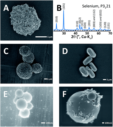
Selenium particles can be obtained from a two-step reaction. (1) First, Na2SeSO3 can be obtained from refluxing commercial selenium with sodium sulfite (Na2SO3). (2) Second, when the pH is lowered to 5 or below with a variety of strong or weak acids, selenium particles are precipitated. This synthetic approach offers more variety than the sulfur-yielding reaction21,22 since the wide choice of acids and optional templating polymers allow the strict control of selenium particle morphology. This is in contrast to sulfur particle generation, which typically requires more hazardous, strong acids such as HCl, H2SO4 or HNO3 to form cohesive sulfur particles. Selenium particles can even be obtained with ascorbic acid (i.e. vitamin C), an example of which is shown in Fig. 1A. All pure selenium particles referred to hereafter were crafted using vitamin C as the acid and were embedded with nanocarbon as a minor conductive additive.21Fig. 1B shows the powder XRD pattern for the synthesized selenium particle. The pattern was fully indexed to a trigonal lattice23 (P3121) and contains no impurity phases. Templating polymers also affect the particle shape, size and morphology. For example, poly(2-acrylamido-2-methyl-1-propanesulfonic acid) (PAMPS) molds the roughly 1 μm selenium particles into spheres as shown in Fig. 1C. Similarly, branched polyethyleneimine (bPEI) templated rod-shaped particles (10 × 3 μm, Fig. 1D) while polystyrene sulfonate (PSS) formed very small spheres of <300 nm in diameter (Fig. 1E) and Nafion resulted in smoother spheres than PAMPS (Fig. 1F). Low molecular weight polyvinylpyrrolidone (PVP) results in rough, crystal-like, hexagonal selenium particles (Fig. S1†). It is noteworthy that all templating agents left a coating on the surface of the selenium particles.19
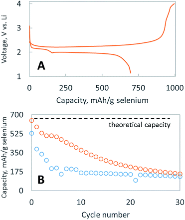
Fig. 2A shows typical discharge and charge potential curves for the selenium particle, embedded with nanocarbon and coated with a single layer of bPEI. When discharged at C/4, it delivered the theoretical capacity (679 mA h g−1 Se) in cycle 1, as shown in Fig. 2B, before decaying to 175 mA h g−1 Se over 30 cycles. The rapid dissolution of polyselenides is likely responsible for the capacity fade, which signifies that the layer of bPEI is not an effective polyselenide dissolution inhibitor. Two possible explanations exist for the failure of the encapsulating layer to retain polyselenides: (1) the volume expansion and contraction of the electrode during cycling might deteriorate the polymer layer, or (2) the polymer coating is non-uniform and porous.
We have previously reported the use of layer by layer (LBL) polymeric films to assemble selectively permeable membranes that allow the fast diffusion of lithium salts but inhibit the diffusion of bulky polysulfides.20,22,24 Two types of membranes were employed: (1) one was built from oppositely charged polymers while the other (2) was self-assembled based on hydrogen bonding.21 This selectively permeable membrane strategy extended the cycle life of lithium–sulfur batteries, suggesting a similar strategy might work to prevent polyselenide dissolution. As such, selenium particles were sequentially coated with a LBL membrane composed of PVP, PAA, PEO and Ketjen black carbon, utilizing hydrogen bonding to adhere each sequential layer (SEM shown in Fig. S2†). As demonstrated in Fig. 2B, this LBL membrane provides a marginal enhancement of the cycle life, in contrast to the dramatic enhancement bestowed upon sulfur particles.19,21,22 Surprisingly, LBL membranes that effectively impede polysulfide dissolution25 are ineffective at impeding polyselenide dissolution. More research is required to find a suitable membrane composition capable of inhibiting the dissolution of polyselenides. Nevertheless, achieving the full discharge capacity in cycle 1 and more than 10 cycles above 50% capacity with a cathode containing >80 wt% active material is difficult. The larger mass of selenium means that a similar atomic ratio of sulfur to carbon in a sulfur cathode would be equivalent to >60 wt% sulfur; however, typical sulfur cathodes able to achieve the theoretical discharge capacity usually only do so with sulfur loadings <40 wt%. Hence, the more facile utilization of selenium is presumably due to its enhanced conductivity vs. sulfur.
A crucial limitation to long cycle life lithium–sulfur or selenium cells is the highly reductive lithium metal negative electrode.24,26 We use a 1 M LiTFSI, 0.02 M LiNO3, DOL![[thin space (1/6-em)]](https://www.rsc.org/images/entities/char_2009.gif) :
:![[thin space (1/6-em)]](https://www.rsc.org/images/entities/char_2009.gif) DME electrolyte despite recent reports that carbonate solvents better limit polyselenide dissolution27 because LiTFSI-in-ether based electrolytes are more stable against reduction and thus cycle lithium metal with higher coulombic efficiencies than LiPF6 in carbonates (comparison in Fig. S3†). Additionally, the discharge curve of selenium in carbonate based electrolytes has a lower average voltage, which lowers the energy density.
DME electrolyte despite recent reports that carbonate solvents better limit polyselenide dissolution27 because LiTFSI-in-ether based electrolytes are more stable against reduction and thus cycle lithium metal with higher coulombic efficiencies than LiPF6 in carbonates (comparison in Fig. S3†). Additionally, the discharge curve of selenium in carbonate based electrolytes has a lower average voltage, which lowers the energy density.
Motivated by the poor cycle life of pure selenium particles, we synthesized hybrid sulfur–selenium particles with the intention of combining the superior cycle life of sulfur with the better conductivity of selenium. Sulfur–selenium hybrids can be obtained by a two-step reaction. (1) First, Na2SeSO3 can be obtained from refluxing commercial selenium with Na2SO3. (2) Second, sodium thiosulfate (Na2S2O3) is added to the refluxing mixture. Sulfur–selenium particles precipitate upon the addition of an acid. Optional templating polymers can be added to the solution, prior to precipitation, to control the particle size and shape. The ratio of Na2S2O3 to Na2SeSO3 in solution does not translate into the same S![[thin space (1/6-em)]](https://www.rsc.org/images/entities/char_2009.gif) :
:![[thin space (1/6-em)]](https://www.rsc.org/images/entities/char_2009.gif) Se ratio in the product; however, increasing the S
Se ratio in the product; however, increasing the S![[thin space (1/6-em)]](https://www.rsc.org/images/entities/char_2009.gif) :
:![[thin space (1/6-em)]](https://www.rsc.org/images/entities/char_2009.gif) Se ratio in solution does increase the ratio in the product, and vice versa. Approximately 1 μm diameter sulfur–selenium particles were produced using bPEI as a templating agent and oxalic acid to precipitate the particles (Fig. S4†).28 Oxalic acid was used to initiate precipitation instead of ascorbic acid because, unlike selenium particles, only low pH acids will precipitate cohesive sulfur (containing) particles.21,22 EDS experiments indicated a uniform, 5
Se ratio in solution does increase the ratio in the product, and vice versa. Approximately 1 μm diameter sulfur–selenium particles were produced using bPEI as a templating agent and oxalic acid to precipitate the particles (Fig. S4†).28 Oxalic acid was used to initiate precipitation instead of ascorbic acid because, unlike selenium particles, only low pH acids will precipitate cohesive sulfur (containing) particles.21,22 EDS experiments indicated a uniform, 5![[thin space (1/6-em)]](https://www.rsc.org/images/entities/char_2009.gif) :
:![[thin space (1/6-em)]](https://www.rsc.org/images/entities/char_2009.gif) 1 weight ratio of sulfur to selenium (Fig. S5†). In general, we observed that a higher selenium ratio results in smaller hybrid particles.
1 weight ratio of sulfur to selenium (Fig. S5†). In general, we observed that a higher selenium ratio results in smaller hybrid particles.
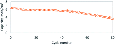
To further improve the conductivity of the active material, we adsorbed Super P Li™ carbon onto the sulfur–selenium hybrid particles, with the aid of the bPEI coating, by ball milling at low energy (SEM Fig. S6A†). To enhance long range electron conductivity, we introduced carbon nanofibers in a second ball milling step, which stick to the carbon coated sulfur–selenium hybrid particles to form a conductive network (SEM Fig. S6B†). To showcase the improvement in cycle life over pure selenium cathodes, we tested cathodes assembled with a high areal capacity (>5 mA h cm−2) of sulfur–selenium hybrid particles. bPEI was used as a templating agent and both Super P Li™ and carbon nanofibers were adhered to the particles, but no protective LBL coating was applied. Typical charge/discharge curves showed significantly reduced overcharge (Fig. S7†), which might correspond to a reduction in dissolution and subsequent shuttling of polysulfide or polyselenide species. The cycling performance of this cell is plotted in Fig. 3 and displays 30% capacity fade over 80 cycles. It is common in the lithium–sulfur or –selenium literature to report an extended cycle life as high as 1000 cycles,24,26 but these results have only been achieved at low areal loadings of sulfur or selenium (<2 mA h cm−2), which corresponds to minimal stripping/plating at the lithium metal anode. Recently, Li et al. has shown the benefit of SeS2-infused carbon electrodes with a protective polymer sheath with high loadings of about 3 mg cm−2 and an impressive cycle life of 500 cycles.29 The cycle life of lithium–sulfur (or –selenium) cells rarely surpasses 100 cycles when larger areal capacities of lithium metal are utilized in standard ethereal or carbonate electrolytes.26 The primary factor limiting cycle life is electrolyte decomposition on the highly reductive lithium metal surface, but exciting new strategies have recently been introduced that could stabilize lithium metal electrodes, thereby granting an upgrade in battery volumetric and gravimetric energy densities.24,26,30 Unfortunately, selenium(–sulfur) based cathodes grant no clear benefit over pure sulfur in terms of cycle life or energy density.24 Considering the health hazard posed by the potential release of H2Se(g) when using selenium, sulfur cathodes appear to be a superior choice.
Conclusions
We describe simple, aqueous synthetic routes for selenium and sulfur–selenium active material, with controllable particle shape and size, that can be used to construct selenium-based cathodes with high areal capacities and mass loadings. Surprisingly, the same LBL membranes that effectively inhibited polysulfide dissolution in Li–S cells did not effectively inhibit polyselenide dissolution in Li–Se cells. Furthermore, the risk of H2Se(g) release when working with selenium outweighs any potential advantage of using selenium over sulfur. Caution: during the TGA analysis of selenium for this research, the release of H2Se(g) caused the shut-down of an external analysis lab. Regardless, the practical implementation of any battery using a lithium metal negative electrode relies on the development of new electrolytes that are stable to lithium metal (or other alkali metals).Conflicts of interest
There are no conflicts to declare.References
- D. U. Eberle and D. R. von Helmolt, Energy Environ. Sci., 2010, 3, 689–699 Search PubMed.
- F. Li, T. Zhang and H. Zhou, Energy Environ. Sci., 2013, 6, 1125–1141 CAS.
- D. Aurbach, B. D. McCloskey, L. F. Nazar and P. G. Bruce, Nat. Energy, 2016, 1, 16128 CrossRef CAS.
- Q. Pang, X. Liang, C. Y. Kwok and L. F. Nazar, Nat. Energy, 2016, 1, 16132 CrossRef CAS.
- G.-L. Xu, J. Liu, R. Amine, Z. Chen and K. Amine, ACS Energy Lett., 2017, 2, 605–614 CrossRef CAS.
- J. He, Y. Chen, W. Lv, K. Wen, P. Li, Z. Wang, W. Zhang, W. Qin and W. He, ACS Energy Lett., 2016, 1, 16–20 CrossRef CAS.
- R. Mukkabla, S. Deshagani, P. Meduri, M. Deepa and P. Ghosal, ACS Energy Lett., 2017, 2, 1288–1295 CrossRef CAS.
- X. Ji, K. T. Lee and L. F. Nazar, Nat. Mater., 2009, 8, 500 CrossRef CAS PubMed.
- Z. Li, H. Bin Wu and X. W. (David) Lou, Energy Environ. Sci., 2016, 9, 3061–3070 CAS.
- S. Xin, L. Yu, Y. You, H.-P. Cong, Y.-X. Yin, X.-L. Du, Y.-G. Guo, S.-H. Yu, Y. Cui and J. B. Goodenough, Nano Lett., 2016, 16, 4560–4568 CrossRef CAS PubMed.
- J. T. Lee, H. Kim, M. Oschatz, D.-C. Lee, F. Wu, H.-T. Lin, B. Zdyrko, W. I. Cho, S. Kaskel and G. Yushin, Adv. Energy Mater., 2015, 5, 1400981 CrossRef.
- G.-L. Xu, T. Ma, C.-J. Sun, C. Luo, L. Cheng, Y. Ren, S. M. Heald, C. Wang, L. Curtiss, J. Wen, D. J. Miller, T. Li, X. Zuo, V. Petkov, Z. Chen and K. Amine, Nano Lett., 2016, 16, 2663–2673 CrossRef CAS PubMed.
- X. Li, J. Liang, Z. Hou, W. Zhang, Y. Wang, Y. Zhu and Y. Qian, Adv. Funct. Mater., 2015, 25, 5229–5238 CrossRef CAS.
- C. Luo, Y. Zhu, Y. Wen, J. Wang and C. Wang, Adv. Funct. Mater., 2014, 24, 4082–4089 CrossRef CAS.
- C.-P. Yang, S. Xin, Y.-X. Yin, H. Ye, J. Zhang and Y.-G. Guo, Angew. Chem., Int. Ed., 2013, 52, 8363–8367 CrossRef CAS PubMed.
- C. Luo, Y. Xu, Y. Zhu, Y. Liu, S. Zheng, Y. Liu, A. Langrock and C. Wang, ACS Nano, 2013, 7, 8003–8010 CrossRef CAS PubMed.
- A. Abouimrane, D. Dambournet, K. W. Chapman, P. J. Chupas, W. Weng and K. Amine, J. Am. Chem. Soc., 2012, 134, 4505–4508 CrossRef CAS PubMed.
- J. Ding, H. Zhou, H. Zhang, T. Stephenson, Z. Li, D. Karpuzov and D. Mitlin, Energy Environ. Sci., 2017, 10, 153–165 CAS.
- C. B. Bucur, J. Muldoon, A. Lita, J. B. Schlenoff, R. A. Ghostine, S. Dietz and G. Allred, Energy Environ. Sci., 2013, 6, 3286–3290 CAS.
- W. Li, G. Zheng, Y. Yang, Z. W. Seh, N. Liu and Y. Cui, Proc. Natl. Acad. Sci. U. S. A., 2013, 110, 7148–7153 CrossRef CAS PubMed.
- C. B. Bucur, J. Muldoon and A. Lita, Energy Environ. Sci., 2016, 9, 992–998 CAS.
- N. Osada, C. B. Bucur, H. Aso and J. Muldoon, Energy Environ. Sci., 2016, 9, 1668–1673 CAS.
- R. Keller, W. B. Holzapfel and H. Schulz, Phys. Rev. B, 1977, 16, 4404–4412 CrossRef CAS.
- C. B. Bucur, M. Jones, M. Kopylov, J. Spear and J. Muldoon, Energy Environ. Sci., 2017, 10, 905–911 CAS.
- K. Han, Z. Liu, J. Shen, Y. Lin, F. Dai and H. Ye, Adv. Funct. Mater., 2015, 25, 455–463 CrossRef CAS.
- P. Bonnick, E. Nagai and J. Muldoon, J. Electrochem. Soc., 2018, 165, A6005–A6007 CrossRef CAS.
- Y. Cui, A. Abouimrane, C.-J. Sun, Y. Ren and K. Amine, Chem. Commun., 2014, 50, 5576–5579 RSC.
- J. Weiss, J. Inorg. Gen. Chem., 1977, 435, 113–118 CAS.
- Z. Li, J. Zhang, H. B. Wu and X. W. (David) Lou, Adv. Energy Mater., 2017, 7, 1700281 CrossRef.
- X.-B. Cheng, R. Zhang, C.-Z. Zhao and Q. Zhang, Chem. Rev., 2017, 117, 10403–10473 CrossRef CAS PubMed.
Footnote |
| † Electronic supplementary information (ESI) available: Experimental methods, additional SEM images of synthesized selenium particles, selenium–sulfur hybrid particles, carbon coatings and selenium electrodes; stripping and plating of Li; EDS and XRD of the sulfur–selenium particles; and potential profile of a S–Se/Li cell. See DOI: 10.1039/c8se00017d |
| This journal is © The Royal Society of Chemistry 2018 |


