Efficient and stable cycling of lithium metal enabled by a conductive carbon primer layer†
Sheng S.
Zhang
 *a,
Xiulin
Fan
b and
Chunsheng
Wang
 b
b
aElectrochemistry Branch, RDRL-SED-C, Sensors and Electron Devices Directorate, U.S. Army Research Laboratory, Adelphi, MD 20783-1138, USA. E-mail: shengshui.zhang.civ@mail.mil; shengshui@gmail.com
bDepartment of Chemical and Biomolecular Engineering, University of Maryland, College Park, MD 20742, USA
First published on 18th September 2017
Abstract
Two requirements must be met for efficient and stable cycling of Li metal: (1) intimate and uniform nucleation of Li metal on an electrode substrate for constant current distribution throughout the electrode surface and (2) chemical and electrochemical stability of electrolyte components for high coulombic efficiency. With a focus on the electrode substrate, in this work, we coat a very thin and highly conductive carbon layer as the Li plating primer onto the surface of an existing Cu substrate. It is shown that the carbon primer layer greatly increases coulombic efficiency and cycling stability of Li metal. Microstructural characterization and ac-impedance analysis reveal that the improvement is due to the preferential nucleation of Li metal on the surface of carbon granules, which results in low contact resistance between the plated Li and the electrode substrate. The results of this work indicate that applying a conductive carbon primer layer is a simple and cost-effective approach for the efficient and stable cycling of Li metal.
Introduction
The desire for pursuing even higher energy density than those of the state-of-the-art Li-ion batteries has driven the research back to rechargeable Li batteries,1 which were previously considered to be unsafe and poorly reversible due to the dendrite growth and cycling inefficiency of the Li metal anode. Regarding the safety, in fact, the excess amount of Li metal is of equal importance with the dendrite growth of Li metal because it immediately becomes a very strong fuel upon being exposed to air or other oxidants in an accident. The most effective solution to this problem is to minimize the amount of excess Li metal by developing a “Li-free battery” to have the Li metal being in situ plated onto the anode substrate from a Li-rich cathode.2,3 The key to the success of this concept is the efficient and stable cycling of Li metal, which is closely associated with the surface of the anode substrate for Li nucleation and the components of electrolyte for high coulombic efficiency.4–6In recent years, dramatic advancement has been made in improving the cycling efficiency and stability of Li metal by studies on two subjects: (1) advanced electrolyte for efficient and stable cycling of Li metal and (2) an anode substrate for intimate and uniform nucleation of Li metal. Regarding the electrolyte, particular interest was shown in a lithium bis(fluorosulfonyl)imide salt, which was either prepared as a highly concentrated salt solution7,8 or dissolved into an ionic solvate9 for reduced reactivity of electrolyte solvents via the Li+–solvent interactions. It has also been reported that fluorinated LiPF6 salt10 and fluoroethylene carbonate solvent11 are able to increase the cycling efficiency and stability of Li metal when they are used as the electrolyte additive and co-solvent, respectively. Besides the above observations, the combination of an ether solvent and a carbonate solvent has shown to optimize the morphology of Li plating and further improve the cycling efficiency of Li metal.12 Regarding the anode substrate, porous carbon-fiber paper13 and porous graphene networks14 have been attempted as the alternative anode substrate, and various nanotechnologies have been adopted to modify the existing anode substrate materials. In the latter efforts, Zhang et al. slurry-coated a functional graphene layer15 or a nitrogen-doped graphene layer16 onto the surface of a planar Cu substrate to enable the dense and uniform deposition of Li metal. Raji et al.17 vertically grafted graphene–carbon nanotube clusters onto the Cu surface by vapor reactions to increase accommodation for Li metal storage, whereas Xin et al.18 deposited spherical carbon granules onto the walls of a 3D Ni foam via the chemical vapor deposition to achieve stable Li plating and stripping. Most recently, Huang et al.19 laminated a highly porous and flexible semi-tubular carbon film onto the top of the Cu surface, leading to a smooth Li surface with protection by the carbon film on its top. By using a crosslinked poly(dimethylsiloxane) elastomer, alternatively, Zhu et al.20 coated a nanoporous polymer membrane onto Cu foil to guide the Li metal plating underneath the polymer membrane with the resultant Li mechanically prevented by the polymer membrane from the growth of Li dendrites. All the above approaches have shown considerable improvement in the Li cycling efficiency and stability. However, such improvements are achieved at high cost either due to the cost of material itself or due to the costly and complicated process.
Aiming to reduce the material cost and simplify the process complexity, in this work, we propose coating a very thin and highly conductive carbon primer layer onto the surface of an existing Cu anode substrate for intimate and uniform nucleation of Li metal. In this way, the Li metal is plated onto the surface of carbon granules, and the carbon conductive networks electrically connect the plated Li and the Cu substrate. In order to highlight the effect of the electrode substrate on the Li nucleation, the testing schedules having a low Li plating capacity and a relatively high current density were used to cycle the Li/Cu cells.21 In this paper, the improvement in the Li cycling efficiency and stability by a highly conductive carbon primer layer will be presented and discussed.
Experimental
Printex® XE2 carbon black (a super conductive carbon black having 30 nm particle diameter and 1000 m2 g−1 specific surface area, commercially available from Degussa, Germany) was coated as the conductive carbon primer layer onto a Cu foil at a 90![[thin space (1/6-em)]](https://www.rsc.org/images/entities/char_2009.gif) :
:![[thin space (1/6-em)]](https://www.rsc.org/images/entities/char_2009.gif) 10 (wt) carbon/binder ratio by using poly(acrylonitrile-methyl methacrylate) (ANMMA, AN/MMA = 94
10 (wt) carbon/binder ratio by using poly(acrylonitrile-methyl methacrylate) (ANMMA, AN/MMA = 94![[thin space (1/6-em)]](https://www.rsc.org/images/entities/char_2009.gif) :
:![[thin space (1/6-em)]](https://www.rsc.org/images/entities/char_2009.gif) 6, MW = 100, 000, Polysciences, Inc.) as the binder and N-methyl pyrrolidinone as the solvent. The resultant electrode was punched into 1.98 cm2 circular disks (i.e., in a 5/8 inch diameter) and dried at 110 °C under vacuum for 16 h. The electrodes with a carbon loading of ∼0.20 mg cm−2 were selected for testing. A solution of 1.0 m LiPF6 dissolved in a 3
6, MW = 100, 000, Polysciences, Inc.) as the binder and N-methyl pyrrolidinone as the solvent. The resultant electrode was punched into 1.98 cm2 circular disks (i.e., in a 5/8 inch diameter) and dried at 110 °C under vacuum for 16 h. The electrodes with a carbon loading of ∼0.20 mg cm−2 were selected for testing. A solution of 1.0 m LiPF6 dissolved in a 3![[thin space (1/6-em)]](https://www.rsc.org/images/entities/char_2009.gif) :
:![[thin space (1/6-em)]](https://www.rsc.org/images/entities/char_2009.gif) 7 (wt) mixture of ethylene carbonate and ethyl methyl carbonate was used as the electrolyte. BR2335-sized coin cells were assembled and filled with 40 μL electrolyte by using a 1.27 cm−2 Li foil disk (being in the area limit) as the counter electrode and a Celgard 3401 membrane as the separator. The Li coin cells were galvanostatically cycled on a Maccor Series 4000 cycler by plating Li metal to a fixed capacity of 0.50 mA h (equaling a 0.39 mA h cm−2 Li loading) and stripping the cell to 0.5 V.
7 (wt) mixture of ethylene carbonate and ethyl methyl carbonate was used as the electrolyte. BR2335-sized coin cells were assembled and filled with 40 μL electrolyte by using a 1.27 cm−2 Li foil disk (being in the area limit) as the counter electrode and a Celgard 3401 membrane as the separator. The Li coin cells were galvanostatically cycled on a Maccor Series 4000 cycler by plating Li metal to a fixed capacity of 0.50 mA h (equaling a 0.39 mA h cm−2 Li loading) and stripping the cell to 0.5 V.
The ac-impedance of the cycled cells was measured using an SI 1260 Impedance/Gain-Phase Analyzer in combination with a Solartron SI 1287 Electrochemical Interface at the frequency from 1.0 × 10⁵ Hz to 0.01 Hz using an ac oscillation of 10 mV amplitude. The cycled electrodes were harvested without washing out of electrolyte salt by dissembling the cell in an argon-filled glovebox, followed by drying and observing the surface morphology on a scanning electron microscopy (SEM, Hitachi SU-70).
Results and discussion
In order to obtain high conductivity while having low carbon loading, super conductive Printex® XE2 carbon black was selected as the carbon material for the Li plating primer layer. The morphologies of the top surface of the carbon primer layer at different magnifications are shown in Fig. 1. It can be observed that the primary structure looks like a cracked paddy rice field showing a number of small and irregular cracks on the carbon plane (see Fig. 1b and c, respectively). A similar surface morphology was previously observed from free-standing poly(ethylene oxide)–SiO2 composite membranes as the content of SiO2 filler was high while the membrane remained very thin.22 This is due to the aggregation of solid particles accompanied by solvent evaporation in the membrane-forming process (i.e., the drying process of slurry), and such cracks can be reduced or even eliminated by optimizing the coating process, for example changing the type of solvent or increasing the rate of solvent evaporation. The secondary structure shows crosslinked carbon networks that are further composed of small spherical carbon granules with an average diameter of ∼70 nm (Fig. 1d).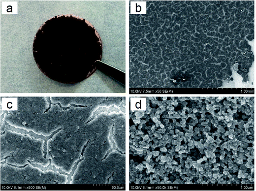 | ||
Fig. 1 Images of the C-coated Cu substrate. (a) Digital photo, (b) SEM, ×50, (c) SEM, ×600, and (d) SEM, ×50![[thin space (1/6-em)]](https://www.rsc.org/images/entities/char_2009.gif) 000. 000. | ||
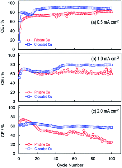
Fig. 2 compares the coulombic efficiencies (CEs) of Li plating and stripping on the pristine Cu substrate and the C-coated Cu substrate, respectively, by plating Li metal to a 0.39 mA h cm−2 capacity and stripping the cell's voltage to 0.5 V at different current densities. Without exception, in the initial several cycles, the C-coated Cu substrate shows relatively lower CEs than the pristine Cu substrate, especially in the first cycle (i.e., 52.2% vs. 69.2% at 1.0 mA cm−2). This phenomenon is common for the carbon materials and can be attributed to the catalytic reduction of electrolyte solvents on the fresh surfaces/edges of carbon granules.23 After the initial activation (or called the formation of the solid electrolyte interphase for the graphite anode in the Li-ion battery community), the C-coated Cu substrate gives higher CEs and more stable CE retention with a general trend that the CE increases with a decrease in the current density. It is interesting to note that the CEs are changed smoothly for the C-coated Cu substrate whereas those for the pristine Cu substrate oscillate irregularly. In the cases of low Li plating capacity, the oscillation of CE is frequently observed and considered to be a symptom for the non-uniform Li nucleation.16 In the present case, the non-uniform Li nucleation is because of the poor electrical contact between the plated Li and the Cu substrate, which will be discussed later.
The voltage profiles of Li plating and stripping are representatively compared in Fig. 3. In the first plating (Fig. 3a), the cell with the C-coated Cu substrate shows irreversible capacities from 0.39 V until −0.082 V at which point stable Li plating initiates and the cell's voltage remains constant, leading to a lower CE (52.2% vs. 69.2% of the pristine Cu substrate) although afterward the Li metal is plated and stripped at very similar voltages in two cells (i.e., at −0.085 V for Li plating and +0.085 V for Li stripping). According to our previous investigation into the SEI formation on the graphite surface,24,25 only these irreversible capacities incurred during the intercalation of Li+ ions into graphite are contributed to the formation of robust SEI. Since the XE2 carbon black is highly amorphous and non-graphitized, few Li+ ions can be intercalated into its structure. Therefore, most of the irreversible capacities observed from the Li/C–Cu cell in the first plating are not responsible for the SEI formation, instead relative to the undesired reduction of electrolyte solvents. In order to minimize the initial irreversibility, further efforts are needed to minimize the loading of carbon and meanwhile improve the electrolyte. In contrast, in the 100th cycle (Fig. 3b, just before the cells were disassembled for SEM observation), the cell with the C-coated Cu substrate has much smaller potentials for both the Li nucleation and Li growth. This is excellent evidence that Li metal is preferentially plated on and stripped from the surface of carbon primer layers. This merit can be simply attributed to the intimate and uniform nucleation of Li metal on the surface of carbon granules, which consequently leads to a lower contact resistance (to be discussed later). It is believed that the similar benefits can also be obtained from all other carbon materials without the need of particular heteroatoms/functional groups or architectural structures, such as graphene-based carbon materials16,26 and carbon nanotubes/fibers,14 as previously reported.
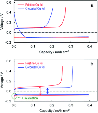 | ||
| Fig. 3 Voltage profiles of Li plating and stripping at 1.0 mA cm−2 on different substrates. (a) 1st cycle and (b) 100th cycle. | ||
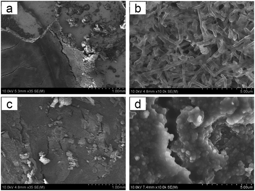
In order to understand the role of the carbon primer layer in the Li nucleation, the surface morphology of the Li plating with a Li loading of 0.39 mA h cm−2 after being plated and stripped at 1.0 mA cm−2 for 100 cycles was observed by using a scanning electron microscope. The surface morphologies of the Li metal plated on two substrates are compared at low magnification (1.00 mm scale, Fig. 4a and c) and high magnification (5.00 μm scale, Fig. 4b and d). On the pristine Cu substrate, the Li metal is plated in the form of laminar planes with irregular cracks, and some Li planes are entirely peeled off the planar Cu substrate (Fig. 4a), showing poor contact between the plated Li and the Cu substrate. The fine structure shows that fibrous Li needles are horizontally laid on the Cu substrate (Fig. 4b). In other words, once the Li nuclei are formed, further Li metal is grown on the Li nuclei in a one-dimensional direction, leading to the formation of fibrous Li needles. In such a case, the Li dendrites would be developed once the resultant fibrous Li needles become mechanically strong and grow vertically from the Cu substrate. In contrast, on the C-coated Cu substrate, no fibrous Li needles are observed except for some small granules and cracks randomly distributed on the surface (Fig. 4c), in which the small granules are believed to be the LiPF6 salt and the small cracks are those pre-existing on the carbon primer layer as shown in Fig. 1c. The fine structure indicates that Li metal is uniformly and smoothly plated on the surface of spherical carbon granules (Fig. 4d), which is further confirmed by a significant increase in the size of carbon granules (Fig. S1†). This observation verifies that Li metal is grown radially outward from the surface of spherical carbon granules, other than in the one-dimensional direction as observed from the pristine Cu substrate. Additionally, the digital photos of the electrodes after 100 cycles indicate that both the Li plating and the Li counter electrode harvested from the C-coated Cu cell are much smoother than those harvested from the pristine Cu cell (Fig. S2†). It is surprising that no isolated Li metal is found in the cracks (Fig. 4d), although the Cu substrate in these crack spots is exposed to the electrolyte. All the above results reveal that Li plating is overwhelmingly preferential to the carbon surface compared with the pristine Cu surface.
The effect of the electrode substrate on Li plating was further studied by using an ac impedance technique. Fig. 5 compares the ac-impedance spectra of two Li/Cu cells employing the pristine Cu and C-coated Cu, respectively. In the Li-plated state (the bottom part of Fig. 5), the impedance spectra show three semicircles, which can be fitted by an equivalent circuit consisting of a bulk resistance (Rb), a surface layer resistance (Rsl), a contact resistance (Rc) between the plated Li and the electrode substrate, and a charge-transfer resistance (Rct) in a descending order of the frequency (Fig. S3†). Using this equivalent circuit, the resistance values are fitted and summarized in Table S1.† It can be seen that with the carbon primer layer, the Rsl and Rc are considerably smaller (i.e., 50 and 51 Ω, respectively, versus 85 and 110 Ω of the pristine Cu cell). Here, the reduction of Rc is excellent evidence for the enhanced electrical contact between the plated Li and the electrode substrate, which verifies our speculation that the Li metal is intimately plated on the surface of the carbon primer layer and electrically adhered to the Cu substrate through the carbon primer layer. On the other hand, in the Li-stripped state (the upper part of Fig. 5), the impedance spectra show two semicircles because there is no Li metal in the working electrode and the Rc no longer exists. In this case, the semicircle at the high frequencies is attributed to the Rsl, and the one at the low frequencies to the Rct. Consistently, the cell with the C-coated Cu has much lower Rsl and Rct although they both are much larger than those in the Li-plated state due to the absence of Li metal in the working electrode. Finally, it should be noted that the carbon primer layer is expected to only improve the Li nucleation. The further growth of Li metal relies more on the electrolyte, which will be the subject of a separate work.
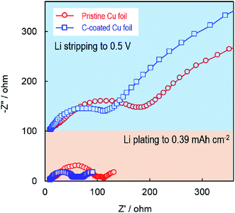 | ||
| Fig. 5 Impedance spectra of Li/Cu cells in the Li-plated state (lower part) and Li-stripped state (upper part), after the cells were cycled for 100 cycles at 1.0 mA cm−2. | ||
Conclusions
In summary, the results of this work show that Li metal is preferentially plated on the surface of carbon granules compared with the pristine Cu substrate. Applying a very thin and highly conductive carbon primer layer onto the Cu substrate considerably increases the coulombic efficiency and cycling stability of Li metal. The role of the carbon primer layer is to promote Li metal intimately and uniformly plating on its surface and electrically connect the plated Li and the Cu substrate. SEM observation and impedance analysis reveal that the carbon primer layer not only homogenizes Li nucleation but also reduces the contact resistance between the plated Li and the electrode substrate, which consequently increases the coulombic efficiency and cycling stability of Li metal. The present work leads to a simple and cost-effective improvement for the efficient and stable cycling of Li metal.Conflicts of interest
There are no conflicts to declare.Acknowledgements
The authors are grateful to Dr C. Lundgren for her critical reading of the manuscript and valuable comments.References
- Battery500 consortium to spark EV innovations, http://www.pnnl.gov/news/release.aspx?id=4295, accessed on 7/1/2017.
- B. J. Neudecker, N. J. Dudney and J. B. Bates, J. Electrochem. Soc., 2000, 147, 517–523 CrossRef CAS
.
- J. F. Qian, B. D. Adams, J. M. Zheng, W. Xu, W. A. Henderson, J. Wang, M. E. Bowden, S. C. Xu, J. Z. Hu and J. G. Zhang, Adv. Funct. Mater., 2016, 26, 7094–7102 CrossRef CAS
.
- W. Xu, J. L. Wang, F. Ding, X. L. Chen, E. Nasybutin, Y. H. Zhang and J. G. Zhang, Energy Environ. Sci., 2014, 7, 513–537 CAS
.
- D. C. Lin, Y. Y. Liu and Y. Cui, Nat. Nanotechnol., 2017, 12, 194–206 CrossRef CAS PubMed
.
- X. B. Cheng, R. Zhang, C. Z. Zhao and Q. Zhang, Chem. Rev., 2017, 117, 10403–10473 CrossRef CAS PubMed
.
- J. Qian, W. A. Henderson, W. Xu, P. Bhattacharya, M. Engelhard, O. Borodin and J. G. Zhang, Nat. Commun., 2015, 6, 6362 CrossRef CAS PubMed
.
- J. M. Zheng, P. F. Yan, D. H. Mei, M. H. Engelhard, S. S. Cartmell, B. J. Polzin, C. M. Wang, J. G. Zhang and W. Xu, Adv. Energy Mater., 2016, 6, 1502151 CrossRef
.
- H. Wang, M. Matsui, H. Kuwata, H. Sonoki, Y. Matsuda, X. F. Shang, Y. Takeda, O. Yamamoto and N. Imanishi, Nat. Commun., 2017, 8, 15106 CrossRef PubMed
.
- J. M. Zheng, M. H. Engelhard, D. H. Mei, S. H. Jiao, B. J. Polzin, J. G. Zhang and W. Xu, Nat. Energy, 2017, 2, 17012 CrossRef
.
- E. Markevich, G. Salitra, F. Chesneau, M. Schmidt and D. Aurbach, ACS Energy Lett., 2017, 2, 1321–1326 CrossRef CAS
.
- H. L. Yu, J. N. Zhao, L. B. Ben, Y. J. Zhan, Y. D. Wu and X. J. Huang, ACS Energy Lett., 2017, 2, 1296–1302 CrossRef CAS
.
- X. Ji, D. Y. Liu, D. G. Prendiville, Y. Zhang, X. Liu and G. D. Stucky, Nano Today, 2012, 7, 10–20 CrossRef CAS
.
- R. Mukherjee, A. V. Thomas, D. Datta, E. Singh, J. Li, O. Eksik, V. B. Shenoy and N. Koratkar, Nat. Commun., 2014, 5, 3710 CAS
.
- R. Zhang, X. B. Cheng, C. Z. Zhao, H. J. Peng, J. L. Shi, J. Q. Huang, J. F. Wang, F. Wei and Q. Zhang, Adv. Mater., 2016, 28, 2155–2162 CrossRef CAS PubMed
.
- R. Zhang, X. R. Chen, X. Chen, X. B. Cheng, X. Q. Zhang, C. Yan and Q. Zhang, Angew. Chem., Int. Ed., 2017, 56, 7764–7768 CrossRef CAS PubMed
.
- A. R. O. Raji, R. Villegas Salvatierra, N. D. Kim, X. Fan, Y. Li, G. A. L. Silva, J. Sha and J. M. Tour, ACS Nano, 2017, 11, 6362–6369 CrossRef CAS PubMed
.
- H. Ye, S. Xin, Y. X. Yin, J. Y. Li, Y. G. Guo and L. J. Wan, J. Am. Chem. Soc., 2017, 139, 5916–5922 CrossRef CAS PubMed
.
- S. Huang, L. Tang, H. S. Najafabadi, S. Chen and Z. Ren, Nano Energy, 2017, 38, 504–509 CrossRef CAS
.
- B. Zhu, Y. Jin, X. Z. Hu, Q. H. Zheng, S. Zhang, Q. J. Wang and J. Zhu, Adv. Mater., 2017, 29, 1603755 CrossRef PubMed
.
- A. Pei, G. Y. Zheng, F. F. Shi, Y. Z. Li and Y. Cui, Nano Lett., 2017, 17, 1132–1139 CrossRef CAS PubMed
.
- S. S. Zhang, J. Electrochem. Soc., 2013, 160, A1421–A1424 CrossRef CAS
.
- S. S. Zhang, J. Power Sources, 2006, 162, 1379–1394 CrossRef CAS
.
- S. S. Zhang, M. S. Ding, K. Xu, J. Allen and T. R. Jow, Electrochem. Solid-State Lett., 2001, 4, A206–A208 CrossRef CAS
.
- S. S. Zhang, K. Xu and T. R. Jow, Electrochim. Acta, 2006, 51, 1636–1640 CrossRef CAS
.
- Z. Liang, D. C. Lin, J. Zhao, Z. D. Lu, Y. Y. Liu, C. Liu, Y. Y. Lu, H. T. Wang, K. Yan, X. Y. Tao and Y. Cui, Proc. Natl. Acad. Sci. U. S. A., 2016, 113, 2862–2867 CrossRef CAS PubMed
.
Footnote |
| † Electronic supplementary information (ESI) available. See DOI: 10.1039/c7se00391a |
| This journal is © The Royal Society of Chemistry 2018 |

