Integration of aligned polymer nanofibers within a microfluidic chip for efficient capture and rapid release of circulating tumor cells†
Yunchao
Xiao
 a,
Mengyuan
Wang
a,
Lizhou
Lin
b,
Lianfang
Du
b,
Mingwu
Shen
a,
Mengyuan
Wang
a,
Lizhou
Lin
b,
Lianfang
Du
b,
Mingwu
Shen
 a and
Xiangyang
Shi
 *a
*a
aState Key Laboratory for Modification of Chemical Fibers and Polymer Materials, College of Chemistry, Chemical Engineering and Biotechnology, Donghua University, Shanghai 201620, P. R. China. E-mail: xshi@dhu.edu.cn
bDepartment of Ultrasound, Shanghai General Hospital, Shanghai Jiaotong University School of Medicine, Shanghai 200080, P. R. China
First published on 15th January 2018
Abstract
Capture and detection of circulating tumor cells (CTCs) is of great significance in the early diagnosis, prognosis evaluation and personalized therapy of cancer. Herein, we report a unique microfluidic platform integrated with zwitterion-modified aligned polyethyleneimine/polyvinyl alcohol nanofibers for efficient capture and rapid release of CTCs. We show that zwitterions of poly(2-methacryloyloxyethyl phosphorylcholine) (PMPC) can be immobilized onto the aligned nanofibers via an atomic transfer radical polymerization approach. The combined strategy of using aligned nanofibers instead of random nanofibers and PMPC immobilization endows the nanofibers with excellent antifouling properties against protein adsorption and blood cell attachment, thereby significantly improving the capture purity of cancer cells. Meanwhile, the targeting ligand folic acid (FA) can be modified onto the surface of nanofibers via a redox-sensitive disulfide bond to specifically and efficiently capture cancer cells overexpressing FA receptors and to rapidly release the cancer cells in a non-destructive manner through tris(2-carboxyethyl)phosphine treatment. The dynamic capture assay using the fiber-integrated microfluidic platform demonstrates that FA receptor-expressing cancer cells can be isolated with a high capture efficiency (92.7%) and considerable purity (43.4%) in a time period of 30 min and can be rapidly detached from the nanofibrous substrates within 5 min with a release efficiency up to 98.9%. These results as well as the isolation and detection of CTCs from the blood of cancer patients suggest that the developed microfluidic chip may be potentially used for clinical cancer diagnosis applications.
Introduction
Over 90% of cancer-related deaths are caused by cancer cell metastases. During the tumor metastatic process, tumor cells are shed from the primary tumor tissue into the bloodstream, becoming the circulating tumor cells (CTCs), and further spread to distant organs.1,2 Detection of CTCs is of great significance for early diagnosis, prediction of cancer development, and evaluation of therapeutic efficacy, prognosis and personalized cancer therapy.3,4 However, it is very difficult to isolate or capture CTCs from blood via conventional means due to the extremely low concentration of CTCs in the blood (approximately one CTC among a billion blood cells).5 For instance, based on density difference, density gradient centrifugation is one of the most classic methods to separate various components of blood. However, during the gradient centrifugation process, CTCs may migrate to the blood plasma layer or remain in red blood cells and neutrophils, resulting in the loss of CTCs during separation.6,7 Flow cytometry can quickly and accurately screen cells, but the operation is complex, and a large amount of peripheral blood is required for effective screening. In addition, according to the cell size difference, membrane filtration is another frequently used approach to separate CTCs from the whole blood, but the separation purity is generally poor.8,9 Therefore, exploration of a highly efficient, simple and high-purity CTC capture technology still remains a challenge.In recent years, microfluidic technology and nanomaterial-based detection platforms have attracted great attention for cell separation.10–13 The geometrical dimensions of the microfluidic channel pretty match the cell size and shape, and thus various operations can be performed by fine control of the flow field around the cells or by tailoring the microstructures of the microfluidic channel.14,15 In addition, the microfluidic chip possesses the advantages of small-size, less sample demand and precise operation, thus becoming an ideal tool for the isolation of CTCs from blood.16,17
Electrospun nanofibers possess extremely large surface area to volume ratio, good biocompatibility, ability to mimic the native extracellular matrix, and the advantages of easy preparation and surface modification.18–21 The large specific surface area provides a large number of cell contact sites, and the active surface groups enable conjugation of various targeting molecules onto the surface of nanofibers, such as anti-EpCAM,22–24 anti-CD146,25 folic acid (FA),26 hyaluronic acid (HA),18,27 DNA aptamer,28etc. Therefore, nanofibers could serve as an ideal platform for cancer cell capture applications.18,26,29,30 For example, polyethyleneimine/polyvinyl alcohol (PEI/PVA) electrospun nanofibers have plenty of surface amine and hydroxyl groups, which enable modification with multiple targeting ligands for specific capture of cancer cells. In our previous work, HA was covalently conjugated onto the surface of electrospun PEI/PVA nanofibers via an N-(3-dimethylaminopropyl)-N′-ethylcarbodiimide/N-hydroxysuccinimide coupling reaction for capturing CD44 receptor-overexpressing cancer cells.15
It has been shown that the desired capture efficiency of CTCs can be achieved through integration of nanomaterials with microfluidic platforms, while the isolation purity of CTCs is generally low for further efficient analysis of CTCs due to the nonspecific adhesion of proteins or blood cells onto the nanomaterial-based substrates.31 In our recent studies, we have shown that zwitterions of cysteine (Cys)32 or carboxybetaine acrylamide33 can be modified onto the surface of magnetic or gold nanoparticles to have significantly improved antifouling properties, decreased macrophage cellular uptake, and extended blood circulation time, which is desirable for magnetic resonance or computed tomographic imaging of different biosystems. Furthermore, zwitterion-functionalized nanomaterials have also proven to have blood-inert surfaces to effectively prevent non-specific adhesion of blood cells.34,35 Therefore, it is reasonable to anticipate that the purity of CTC capture may be significantly enhanced by modifying zwitterions onto the surface of substrates or microfluidic channels. Additionally, random nanofibers might cause more non-specific adhesion of blood cells due to the porous network structure, resulting in a relatively low purity of captured cancer cells. Thus, employing aligned nanofibers instead of random nanofibers may be a feasible approach to reduce blood-cell attachment and finally improve the capture purity of cancer cells. By combining the strategies of aligned nanofibers and zwitterion modification, we attempt to endow the nanofibers with excellent antifouling properties against blood cells, thus achieving a high-purity capture of cancer cells.
For efficient analysis of CTCs, such as gene sequencing and the in vitro drug susceptibility test, the captured CTCs should be effectively dissociated from the capture matrix in a non-destructive manner.36 In principle, the methods used for the release of CTCs from the substrate always cause damage to the CTCs and result in decreased cell viability. In addition, a relatively longer treatment time period also causes more damage to cancer cells. Therefore, it is necessary to realize a rapid and intact release of CTCs. The disulfide bond is able to be rapidly ruptured by reducing agents such as dithiothreitol (DTT),37 glutathione (GSH),38 and tris(2-carboxyethyl)phosphine (TCEP).39,40 For this reason, the disulfide bond has been used as an intermediate linker to modify drug molecules onto nanoparticles to achieve the rapid release of anti-cancer drugs in a reductive tumor microenvironment.41 This leads us to speculate that CTCs captured onto a nanofiber substrate modified with a targeting ligand via a disulfide bond may be rapidly released for further assays.
In this study, we designed a unique microfluidic chip system integrated with zwitterion-functionalized aligned PEI/PVA nanofibers for efficient capture and rapid release of CTCs (Fig. 1). Firstly, aligned PEI/PVA nanofibers were brominated and modified with zwitterions of poly(2-methacryloyloxyethyl phosphorylcholine) (PMPC) via an atomic transfer radical polymerization (ATRP) reaction. Meanwhile, the targeting ligand containing a disulfide bond was synthesized by thiol oxidation of Cys and SH–PEG–FA (a PEGylated folic acid with one end of sulfhydryl group), and then was modified on the surface of nanofibers via reaction with the bromide group (Fig. S1, ESI†). The functionalized nanofibers were systematically characterized using different techniques and then integrated with a herringbone microfluidic channel system. The integrated microfluidic platform was used for dynamic capture and release of cancer cells. The viability of the released cells was also tested through a standard method. Furthermore, blood samples collected from cancer patients were used for the capture and release of CTCs using our microfluidic device to determine its potential clinical applications. To our knowledge, this is the first example using a microfluidic chip system integrated with aligned PEI/PVA nanofibers for highly efficient capture and rapid release of CTCs.
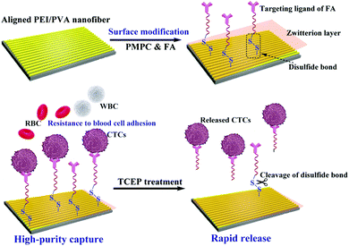 | ||
| Fig. 1 Schematic illustration of the functionalization of the aligned PEI/PVA nanofibrous mat for highly efficient capture and rapid release of CTCs. | ||
Results and discussion
Preparation and characterization of the PEI/PVA–PMPC–FA nanofibrous mat
FA receptors are cell-surface glycoproteins that bind FA with a high affinity,42 and are expressed at a very low level in normal cells, but are generally overexpressed in various cancer cells such as KB,43 M109,44 HeLa,45 and SKOV-3.46 Therefore, in this study, we selected FA as a targeting ligand for selective cancer cell capture.Firstly, Cys–PEG–FA was synthesized via a thiol oxidation reaction and was characterized by FTIR and 1H NMR. As shown in Fig. S2a (ESI†), the peak at 2591 cm−1 can be assigned to the characteristic peak of the sulfhydryl group in SH–PEG–FA, while the peak at 2591 cm−1 vanishes in the FTIR spectrum of Cys–PEG–FA, and a new peak attributed to disulfide (–S–S–) absorption appears at 456 cm−1. This suggests that the disulfide bond has been successfully formed. In Fig. S2b (ESI†), the chemical shifts at 7.53 ppm and 6.67 ppm are assigned to the benzene ring of FA, and those at 3.35 ppm and 1–2 ppm correspond to the methylene protons of PEG and the sulfhydryl (–SH) protons of SH–PEG–FA, respectively. In comparison with the 1H NMR spectrum of SH–PEG–FA, the characteristic protons of sulfhydryl (–SH) disappear in the 1H NMR spectrum of Cys–PEG–FA. Taken together, both 1H NMR and FTIR spectra reveal the successful synthesis of Cys–PEG–FA by conjugation of cysteine with SH–PEG–FA via a disulfide bond.
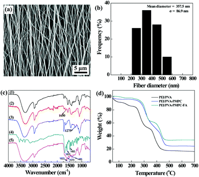
The aligned PEI/PVA nanofibers were then formed via electrospinning, followed by GA vapor crosslinking to endow them with water stability. The crosslinked PEI/PVA nanofibers were observed using scanning electron microscopy (SEM). As can be seen in Fig. 2a, the PEI/PVA nanofibers possess a uniform morphology with a good orientation and with a mean diameter of 357 nm (Fig. 2b).
After that, the crosslinked PEI/PVA nanofibers were sequentially modified with PMPC and Cys–PEG–FA, which was confirmed by attenuation total reflection-Fourier transform infrared (ATR-FTIR) spectroscopy (Fig. 2c). For pristine PEI/PVA nanofibers (curve 1), the peak at 3301 cm−1 is attributed to the hydroxyl groups of PVA, and the peaks appearing at 2850 cm−1 and 2935 cm−1 correspond to the symmetric and asymmetric stretching vibration of methine (–CH–), respectively. The peaks at 1566 cm−1 and 653 cm−1 are associated with the bending vibration of –NH–, and the peak at 1325 cm−1 can be assigned to C–N stretching vibration absorption of PEI. After GA crosslinking, a new peak appears at 1650 cm−1 in curve 2 (crosslinked PEI/PVA), which is the characteristic peak of –CH![[double bond, length as m-dash]](https://www.rsc.org/images/entities/char_e001.gif) N– formed by the conjugation of partial surface amines of PEI and aldehyde groups of GA. After PMPC modification (curve 3), a new peak corresponding to P
N– formed by the conjugation of partial surface amines of PEI and aldehyde groups of GA. After PMPC modification (curve 3), a new peak corresponding to P![[double bond, length as m-dash]](https://www.rsc.org/images/entities/char_e001.gif) O of PMPC appears at 1275 cm−1, suggesting that PMPC has been successfully immobilized on the surface of PEI/PVA nanofibers. Moreover, by comparison of curves 2 and 3, the peaks at 1570 cm−1 and 1485 cm−1 appear in curve 5 (PEI/PVA–PMPC–FA), which are assigned to the characteristic adsorption peaks of the benzene ring of FA (curve 4, Cys–PEG–FA), indicating that the targeting ligand of FA has been successfully modified on the surface of nanofibers.
O of PMPC appears at 1275 cm−1, suggesting that PMPC has been successfully immobilized on the surface of PEI/PVA nanofibers. Moreover, by comparison of curves 2 and 3, the peaks at 1570 cm−1 and 1485 cm−1 appear in curve 5 (PEI/PVA–PMPC–FA), which are assigned to the characteristic adsorption peaks of the benzene ring of FA (curve 4, Cys–PEG–FA), indicating that the targeting ligand of FA has been successfully modified on the surface of nanofibers.
Thermogravimetric analysis (TGA) was used to quantify the composition of the PMPC and Cys–PEG–FA modified onto the nanofiber surface (Fig. 2d). PEI/PVA displays a weight loss of 83.8% at 700 °C under a nitrogen atmosphere, while the PEI/PVA–PMPC nanofibrous mat has a weight loss of 75.7% under the same conditions. Hence, the percentage of PMPC modified on the nanofibrous mat can be calculated to be 8.1 wt%. Similarly, it can be calculated that the mass percentage of Cys–PEG–FA immobilized on the nanofibrous mat is about 9.6 wt%.
Hemocompatibility assays of functional nanofibers
Hemolysis and dynamic clotting assays were performed to evaluate the hemocompatibility of nanofibrous mats before and after surface modification (Fig. S3, ESI†). In Fig. S3a (ESI†), the hemolysis rates of human red blood cells (HRBCs) treated with different nanofibrous mats are all less than the threshold value of 5%,18,47 suggesting that the formed PEI/PVA nanofibrous mats before and after surface modification do not cause hemolysis of RBCs, similar to the negative control of PBS. In contrast, HRBCs exposed to water display a severe hemolysis effect (inset of Fig. S3a, ESI†). Dynamic coagulation assay results (Fig. S3b, ESI†) show that the OD values for the PEI/PVA mat group are higher than those for the control group (cover slip) at the same time points, indicating the good anticoagulant activity of the nanofibrous mats. After functionalization with PMPC or PMPC–FA, the OD values for both PEI/PVA–PMPC and PEI/PVA–PMPC–FA groups are higher than those for the control group and the PEI/PVA group, suggesting that modification of PMPC or PMPC–FA enhances the anticoagulation effect of the fibrous mats. Taken together, we can safely conclude that the PEI/PVA–PMPC–FA nanofibrous mat possesses an excellent hemocompatibility.Antifouling properties of nanofibrous mats
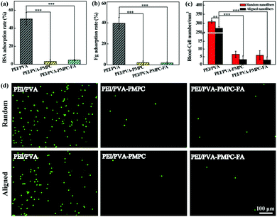
Protein adsorption and blood cell attachment assays were used to investigate the antifouling properties of the zwitterion-modified aligned nanofibrous mats. Random nanofibers were also evaluated for comparison. As shown in Fig. 3a and b, the protein (bovine serum albumin (BSA) and fibrinogen (Fg)) adsorption rates for both PEI/PVA–PMPC and PEI/PVA–PMPC–FA significantly decrease when compared with the non-modified PEI/PVA nanofibrous mat (p < 0.001). The blood-cell attachment results of both random and aligned nanofibrous mats are shown in Fig. 3c. The density of blood cells adhered on the random PEI/PVA nanofibrous mat is over 300 mm−2, which is higher than that attached on the aligned PEI/PVA nanofibrous mat (273 mm−2, p < 0.01). After PMPC modification, the blood-cell density on both random and aligned nanofibrous mat is merely 2–7 mm−2. It seems that the density of blood cells attached onto the random nanofibrous mat is slightly higher than that attached onto the aligned nanofibrous mat, although no significant differences were observed. This clearly demonstrates that zwitterion-modified nanofibrous mats possess excellent blood cell anti-adhesion performance. The blood cell anti-adhesion performance was further confirmed by fluorescence microscopic observation of the adhered WBCs on the different fibrous mats (Fig. 3d). Apparently, PMPC functionalization with or without further FA modification significantly reduces the blood-cell attachment on the fibrous mats, thus endowing the fibrous mats with an excellent blood-inert property.Static cancer cell capture and release assays
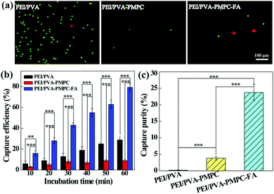
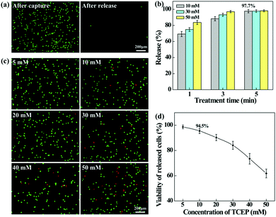
The aligned nanofibrous mats were used for static capture of cancer cells (Fig. 4). Fluorescence microscopic images (Fig. 4a) show that HeLa cells (red) and plenty of WBCs (green) are attached on the PEI/PVA nanofibrous mat after incubation for 1 h, while only a few WBCs are attached on the PEI/PVA–PMPC nanofibrous mat. Compared with PEI/PVA and PEI/PVA–PMPC mats, the PEI/PVA–PMPC–FA mat is able to capture more HeLa cells likely due to the presence of FA ligands. Further quantitative analysis (Fig. 4b) reveals that the capture efficiency of HeLa cells gradually increases with the extension of incubation time for all three types of nanofibers. At each time point, the capture efficiency of the PEI/PVA–PMPC–FA nanofibers is significantly higher than that of the PEI/PVA and PEI/PVA–PMPC nanofibers, suggesting that FA modification could achieve specific capture of FA receptor-expressing cancer cells with a high efficiency. At the incubation time of 60 min, the capture efficiency of HeLa cells using PEI/PVA–PMPC–FA nanofibers reaches up to 78.9%. We further checked the capture purity of three kinds of nanofibers (Fig. 4c). Obviously, the capture purities of PEI/PVA–PMPC–FA and PEI/PVA–PMPC mats are higher than that of the PEI/PVA mat (p < 0.001). This implies that the zwitterion PMPC modification could reduce the adhesion of WBCs on the nanofibrous mats and further improve the final capture purity of cancer cells. In addition, the capture purity of the PEI/PVA–PMPC–FA mat is much higher than that of the PEI/PVA–PMPC mat (p < 0.001), which further demonstrates the role played by the targeting ligand FA in specific cancer cell capture.To release the captured HeLa cells from the PEI/PVA–PMPC–FA fibrous mats, the cells were treated with various concentrations of TCEP for different time periods. TCEP is known to be an efficient reducing agent to break disulfide bonds within 5 min at room temperature.39,40,48 Hence, we selected TCEP to break the disulfide bonds between FA and PMPC for rapid release of cancer cells. As shown in Fig. 5a, almost all of the captured HeLa cells are able to be released from the nanofibrous mat after treatment with TCEP for 5 min. The release efficiency increases with the extension of treatment time (Fig. 5b), and reaches up to 97.7% at 5 min. At the same treatment time, the release efficiency does not seem to have a significant difference when TECP at different concentrations was used. At the lowest concentration (10 mM) of TCEP and at the shortest time period of 1 min, the release efficiency of cancer cells can reach up to 69.3%.
We also investigated the impact of TCEP concentration on the viability of the released cells by live–dead cell staining (Fig. 5c). It can be seen that when the TECP concentration is lower than 20 mM, a few dead (red) cells can be found in the recovered cell suspension, while the dead (red) cells increase sharply at the TECP concentration over 40 mM. This suggests that TCEP at a low concentration scarcely causes damage to cancer cells, while TCEP at a high concentration starts to impair cancer cells. This can be further confirmed by quantitatively measuring the viability of the released HeLa cells (Fig. 5d), where over 90% of cells remain viable after treatment with TCEP at lower concentrations (<20 mM) for 5 min. Hence, in the subsequent dynamic release assays, we selected the TCEP concentration at 10 mM.
Dynamic capture and release of cancer cells using a fiber-integrated microfluidic system
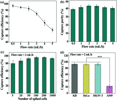
We next checked the feasibility of using the designed microfluidic chip integrated with the PEI/PVA–PMPC–FA nanofibrous mat for dynamic capture and release of cancer cells. The effect of flow rate on the capture efficiency and capture purity was first investigated (Fig. 6a). The capture efficiency decreases with the increase of flow rate and declines sharply at a flow rate over 3 mL h−1. At a flow rate of 2 mL h−1, the cell capture efficiency still remains more than 90%. It should be noted that the dynamic capture efficiency is obviously higher than that under static conditions. This may be due to the fact that the height of our microfluidic channel allows monolayered or double-layered cells to pass through the microfluidic chip, ensuring sufficient interaction between single cancer cells and targeting ligand-modified fiber substrates. Further, the herringbone microfluidic channel could generate turbulence, thus increasing the interaction and collision probability between substrates and cancer cells.49,50In addition, the capture purity of cancer cells under various flow rates was also determined (Fig. 6b). The developed microfluidic chip is able to capture HeLa cells with considerable purity (39.3–43.4%) under different flow rates, and at a flow rate of 2 mL h−1, the capture purity is the highest (43.4%). As a visual confirmation (Fig. S4, ESI†), only a few WBCs are trapped in the microfluidic chip, showing a fairly high purity of the captured cancer cells. We therefore selected the flow rate of 2 mL h−1 for subsequent studies.
In order to investigate the detection limit of the microfluidic chip system, the cell capture efficiency was analyzed by spiking different numbers of HeLa cells with WBCs (Fig. 6c). The capture efficiency increases initially and tends to be stable with the increase of cancer cell concentration. The microfluidic device exhibits an excellent capture efficiency (80.2–96.4%) in the cancer cell density range of 5–1000 per mL, which is sensitive enough for clinical blood samples with a CTC density at a few to hundred cells per mL of blood.
Furthermore, the capture efficiency of different types of cancer cells was also studied to confirm the versatility of the microfluidic chip. It can be seen from Fig. 6d that the fiber-integrated microfluidic chip enables highly efficient capture of FA receptor-overexpressing cancer cells (KB, HeLa, or SKOV-3) with an efficiency in the range of 92.3–93.5%. In contrast, the efficiency to capture A549 cells having a low-level FA receptor expression is much lower (p < 0.001). These results indicate that the fibrous mat-integrated microfluidic chip can be used for highly efficient capture of multiple types of cancer cells expressing FA receptors.
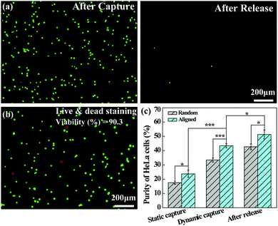
The dynamically captured cancer cells can also be released by inletting TCEP solution through the microfluidic channel. Fig. 7a shows that a majority of the captured HeLa cells are released from the microfluidic chip after treatment with 10 mM TCEP for 5 min at a flow rate of 4 mL h−1. The release efficiency can be calculated to be 98.9%. Furthermore, as shown in Fig. 7b, only a few dead (red) cells can be found in the recovered cell suspension and the viability of the released cells is still up to 90.3%, which is slightly lower than that under static assay conditions (94.5%) after treatment with 10 mM TCEP for 5 min. This suggests that the possible shear force and collision in the microfluidic chip do not seem to cause a significant damage or deformation to the cancer cells. Additionally, we compared the purity of HeLa cells captured on the aligned and random nanofibrous mats under either static or dynamic conditions, and the capture purity of HeLa cells in the recovered solution after release. As can be seen in Fig. 7c, the purity of HeLa cells is further enhanced after release, being higher than that of static capture and dynamic capture, reaching up to 51.3% after their release from the aligned nanofibers. The improved capture purity is likely due to the fact that a portion of WBCs trapped in the nanofibrous mat could not be detached from the nanofibrous mat, whereas the cancer cells have quite a high release percentage under the same treatment conditions. According to eqn (2), by calculating the numbers of WBCs with a decreased portion and cancer cells in the receiving tank, the purity of cancer cell capture should be enhanced. Under dynamic conditions, the capture purity of aligned nanofibers is significantly higher (p < 0.001) than that of random nanofibers, suggesting that aligned nanofibers indeed enhance the capture purity of cancer cells due largely to the lower blood-cell attachment on aligned nanofibers. We note that the capture purity under dynamic conditions (43.4%) is much higher than that under static conditions (23.7%), suggesting that the nanofiber-integrated microfluidic chip is able to effectively improve the capture purity, likely due to the low adhesion of blood cells under flowing conditions.
Clinical utility
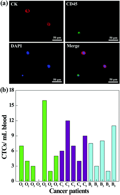
To further investigate the clinical applications of our microfluidic chip system, we next tested its utility to capture CTCs from the blood of cancer patients. Prior to processing the whole blood samples, a comparative study was conducted to investigate the capture efficiency of cancer cells in different media (culture medium, RBC-lysed blood, or healthy human whole blood). As shown in Fig. S5 (ESI†), the capture efficiencies in three different media are close, and the capture efficiency in whole blood is sufficiently high (86.5%) for CTC capture. Therefore, the blood of cancer patients was processed directly without dilution or labeling, and the CTCs in 1 mL of blood were captured and released using the fibrous mat-integrated microfluidic chip system. The released CTCs were subjected to immunostaining and were counted under a fluorescence microscope (Fig. 8). According to the cell identification criteria, the isolated CTCs are 4′,6-diamidino-2-phenylindole (DAPI)+ (blue)/CK+ (red)/CD45− cells, while WBCs are DAPI+ (blue)/CK−/CD45+ (green) cells (Fig. 8a). Blood from different cancer patients was analyzed (Fig. 8b). The results show that 6 of 7 ovarian cancer patients, 5 of 5 cervical cancer patients, and 5 of 5 breast cancer patients are successfully diagnosed to have the CTCs (ranging from 1 to 16 CTCs mL−1) using the developed fibrous mat-integrated microfluidic chip system. Our data indicate that the microfluidic device is able to isolate and detect CTCs from the whole blood of cancer patients.Conclusions
In summary, we developed a unique microfluidic platform integrated with zwitterion-modified aligned nanofibers for highly efficient capture and rapid release of CTCs. Aligned PEI/PVA nanofibers are able to be modified with zwitterions of PMPC via ATRP and further functionalized with FA through a redox-sensitive disulfide bond linker. The formed PMPC-functionalized nanofibrous mats display excellent antifouling property against protein and blood cell adhesion, are hemocompatible, and are able to effectively and specifically capture FA receptor-overexpressing cancer cells with a high purity (e.g., for HeLa cells, 43.4%) and a capture efficiency up to 92.7% within 30 min under dynamic microfluidic conditions. Furthermore, the use of the fiber-integrated microfluidic platform for detection of CTCs from cancer patients was proven to be successful. Overall, the developed aligned fiber-integrated microfluidic device may be potentially used for CTC capture and rapid release for clinical cancer diagnosis applications.Experimental
Preparation of electrospun PEI/PVA nanofibers
Through electrospinning technology, aligned PEI/PVA nanofibers were prepared using a high-speed rotating drum as the collecting device. Simultaneously, the random PEI/PVA nanofibers were also prepared for comparison. Then, the prepared PEI/PVA nanofibrous mats were crosslinked by glutaraldehyde (GA) vapor to endow them with water stability according to our previous work.18,29 To be specific, 10 wt% PEI/PVA electrospinning solution was prepared and suctioned into a 10 mL syringe equipped with a No. 18 stainless steel needle. The electrospinning was conducted with a high voltage of 25 kV, a flow rate of 0.3 mL h−1 and a collecting distance of 10 cm under an ambient environment (about 35% humidity and 25 °C). The PEI/PVA nanofibrous mats were collected on a rotating drum with a speed of 2600–3000 r min−1 to obtain aligned nanofibers, and a speed of 50–100 r min−1 to acquire random nanofibers. The fibrous mats were then crosslinked by GA vapor in a vacuum desiccator for 6 h. After crosslinking, the PEI/PVA nanofibrous mats were vacuum dried at 60 °C for 24 h to remove the residual moisture and GA.Zwitterion modification of nanofibers
Zwitterion modification was carried out via a two-step ATRP of MPC on the crosslinked PEI/PVA nanofibers (Fig. S1, ESI†). In the first step, brominated PEI/PVA nanofibers were acquired. Briefly, PEI/PVA mats were immersed in dichloromethane (10 mL) containing 500 μL of triethylamine and 412 μL of 2-bromoisobutyryl bromide was dropwise added into the above solution in an ice bath under a nitrogen atmosphere. The mixture was stirred for 4 h at 0 °C and subsequently stirred for 8 h at room temperature. After the reaction, the mats were ultrasonically rinsed using dichloromethane, ethanol, and water (with each 3 times), respectively. The formed brominated PEI/PVA nanofibers (PEI/PVA–Br) were dried in vacuum for 24 h at 40 °C.In the second step, PMPC was anchored onto the PEI/PVA–Br nanofibers via ATRP. To be short, 107 mg of CuBr, 1.77 g of MPC and 234 mg of 2,2′-bipyridine were co-dissolved in a mixture of water and methanol (volume ratio of 1![[thin space (1/6-em)]](https://www.rsc.org/images/entities/char_2009.gif) :
:![[thin space (1/6-em)]](https://www.rsc.org/images/entities/char_2009.gif) 1, 25 mL), and PEI/PVA–Br nanofibrous mats were put into the mixture solution under stirring. After 2 h reaction under nitrogen protection, the nanofibrous mats were taken out and ultrasonically rinsed with ethanol and water (with each 3 times), respectively. Then the PMPC-functionalized PEI/PVA nanofibers (PEI/PVA–PMPC–Br) were obtained after vacuum drying for 24 h at 60 °C.
1, 25 mL), and PEI/PVA–Br nanofibrous mats were put into the mixture solution under stirring. After 2 h reaction under nitrogen protection, the nanofibrous mats were taken out and ultrasonically rinsed with ethanol and water (with each 3 times), respectively. Then the PMPC-functionalized PEI/PVA nanofibers (PEI/PVA–PMPC–Br) were obtained after vacuum drying for 24 h at 60 °C.
Synthesis of Cys–PEG–FA segments
PEGylated FA with one end of sulfhydryl group (SH–PEG–FA, 37.2 mg) was dissolved in 3 mL of water, followed by addition of 2.42 mg of cysteine (Cys) under magnetic stirring. Then, H2O2 (30 wt%, 10 μL) was added into the above solution under an ice bath. After stirring for 1 h, the mixture was dialyzed against water (2 L, for 3 days) using a cellulose dialysis membrane with a molecular weight cut-off (MWCO) of 1000. Afterwards, the formed Cys–PEG–FA was lyophilized for subsequent use.Preparation of PEI/PVA–PMPC–FA nanofibers
The obtained Cys–PEG–FA was dissolved in 20 mL of DMSO, into which 2.1 mg of potassium carbonate was added under stirring. After that, the PEI/PVA–PMPC–Br mats were added into the mixture solution, and the reaction system was heated up to 75 °C. After reaction for 6 h, the mats were taken out and ultrasonically cleaned with methanol and water (with each 3 times), respectively. The final product of PMPC- and FA-functionalized PEI/PVA nanofibrous mats (PEI/PVA–PMPC–FA) was harvested after vacuum drying.Static capture and release of cancer cells
Firstly, white blood cells (WBCs) were acquired from fresh human blood by lysing red blood cells. Then, WBCs were stained with calcein AM, resuspended in cell culture medium, and counted using a Scepter 2.0 Handheld Automated Cell Counter (Merck Millipore, Darmstadt, Germany). Afterwards, a number of HeLa cells (human cervical carcinoma cell line) were blended into the WBC suspension to obtain the mixed cell suspension. In order to facilitate the follow-up counting, HeLa cells were stained with calcein red before the incorporation. Next, circular nanofibrous mats with a diameter of 14 mm were placed in a 24-well plate with each mat in each well. Each circular mat was immersed in 500 μL of phosphate buffered saline (PBS) and equilibrated for 24 h under ultraviolet irradiation. After equilibration, 1 mL of culture medium containing 106 pre-stained WBCs and 200 pre-stained HeLa cells was added into each well of the 24-well plate, and incubated at 37 °C for different time periods (10, 20, 30, 40, 50, and 60 min, respectively). For each time interval, 4 parallel specimens were tested. Subsequently, the mat in each well was rinsed three times with PBS (500 μL for each time) and then the numbers of HeLa cells (red) and WBCs (green) attached onto the nanofibrous mats were counted under a fluorescence microscope. All the fluorescence microscopic images of cells were collected using a 20× objective lens. Finally, the capture efficiency and capture purity of cancer cells were calculated viaeqn (1) and (2):| Capture efficiency (%) = NC/NT × 100% | (1) |
| Capture purity (%) = NC/(NC + NW) × 100% | (2) |
To release the captured cancer cells from the PEI/PVA–PMPC–FA nanofibrous mats, each mat with a diameter of 14 mm was placed into each well of a 24-well plate and equilibrated in 500 μL of PBS under ultraviolet irradiation for 24 h. Then, 500 μL of culture medium containing 104 calcein AM-prestained HeLa cells was added into each well and incubated at 37 °C for 1 h. Subsequently, each mat in the well was rinsed three times with 500 μL of PBS to remove the non-adherent cells and then HeLa cells captured on the nanofibrous mats were imaged and counted under a fluorescence microscope (10× objective lens). After that, 500 μL of TCEP with different concentrations (10 mM, 30 mM, or 50 mM) was added into each well and incubated for different time periods (1, 3, or 5 min), and at each time point, quadruplicate samples were tested. After treatment with TCEP for a predetermined time interval, the nanofibrous mats were rinsed and observed following the same steps as described above. The cell release efficiency was calculated by eqn (3):
| Release efficiency (%) = (NC − NR)/NC × 100% | (3) |
Next, we conducted live–dead cell staining assay to investigate the cell viability of the released cancer cells after treatment with TCEP at different concentrations (5, 10, 20, 30, 40, or 50 mM) for 5 min. Experimental procedures were similar to those described above. The only difference is that HeLa cells were not prestained. The recovered solution was collected and subjected to live–dead cell staining, and the live (green) and dead (red) cancer cells were counted under a fluorescence microscope. The viability of the released cancer cells was calculated through eqn (4):
| Viability (%) = NL/(NL + ND) × 100% | (4) |
Fabrication of a fiber-integrated microfluidic chip system
We used Auto CAD software to design the herringbone microfluidic channel system,17,51 which includes an inlet, an outlet and four parallel herringbone channels for CTC capture. In detail, the height of the microfluidic channel and the herringbone channel was 40 μm and 30 μm, respectively. And the total length from the inlet to the outlet was 65 mm; the herringbone channel length was 45.5 mm; the total width of four parallel herringbone channels was 20 mm; and the width of the single fishbone channel was 4 mm (Fig. S6a, ESI†). Subsequently, a channel mask was printed out through a high-resolution printer, followed by photoetching of the microfluidic channel mold in a silicon wafer via photolithography. Finally, the transparent microfluidic channel plate was obtained by casting polydimethylsiloxane (PDMS) on the microfluidic channel mold.The microfluidic chip was fabricated using plasma bonding technology. In brief, by taking the PEI/PVA–PMPC–FA nanofibrous mat-loaded glass slide as a substrate, the PDMS microfluidic channel plate was bonded with the glass slide after treatment with plasma for 40–50 s in air (20–26 Pa). After that, the nanofiber-integrated microfluidic chip was fabricated (Fig. S6b, ESI†).
Dynamic capture and release of cancer cells
Dynamic capture and release of cancer cells were carried out using a microfluidic chip system integrated with the PEI/PVA–PMPC–FA nanofibrous mat. Firstly, the mixed suspension of HeLa cells and WBCs was obtained as described above. Before passing through the mixed cell suspension, the microfluidic chip was continuously pumped with PBS at a flow rate of 4 mL h−1 to ensure that the channel and nanofibers were sufficiently equilibrated. First of all, the dynamic capture efficiency and capture purity of HeLa cells under different flow rates were investigated. In brief, 1 mL of the mixed cell suspension with a WBC concentration of 106 mL−1 and a HeLa cell concentration of 200 mL−1 was introduced into the microfluidic chip at various flow rates (0.5, 1, 2, 3, 4, and 5 mL h−1, respectively). After that, the microfluidic channel was washed by inletting PBS for 5 min at a flow rate of 4 mL h−1 and then the cells captured on the nanofiber substrate were observed and counted under a fluorescence microscope. And the capture efficiency and capture purity were calculated according to eqn (1) and (2), respectively. Subsequently, the dynamic capture efficiency of HeLa cells at different concentrations was determined. The mixed cell suspension (1 mL) with a WBC concentration of 106 mL−1 and a HeLa cell concentration of 5 mL−1, 20 mL−1, 50 mL−1, 100 mL−1, 200 mL−1, or 1000 mL−1 was passed through the microfluidic chip at an optimum flow rate. The dynamic capture efficiency of HeLa cells at different concentrations was calculated according to eqn (1). Moreover, the dynamic capture efficiency of different kinds of cancer cells (KB, HeLa, SKOV-3, or A549) with a concentration of 200 mL−1 was explored under the same conditions.To release the captured cancer cells from the fibrous mats, we first introduced HeLa cells pre-stained with calcein-AM (1 mL, 104 mL−1) to the microfluidic chip. The microfluidic chip was washed by pumping PBS and then HeLa cells captured onto the nanofibrous mats were observed and counted using a fluorescence microscope (10× objective lens). Then, TCEP (10 mM) was introduced into the microfluidic chip at a flow rate of 4 mL h−1 for 5 min. After that, the residual HeLa cells attached onto the nanofibrous mats were observed and counted under a fluorescence microscope, and the release efficiency of cancer cells was calculated according to eqn (3).
In order to investigate the viability of released HeLa cells, HeLa cells (1 mL, 104 mL−1) were pumped into the microfluidic chip. After passing through TCEP (10 mM) for 5 min, the recovered solution was collected and subjected to a live–dead cell staining assay. The live (green) and dead (red) cancer cells were counted under a fluorescence microscope (10× objective lens). Finally, the viability of released cancer cells was calculated according to eqn (4).
Clinical utility
Fresh whole blood of cancer patients was received from Shanghai General Hospital (Shanghai, China) after approval by the ethical committee of Shanghai General Hospital. Without any pretreatment, 1 mL of the whole blood was directly passed through our microfluidic device at a flow rate of 2 mL h−1. The CTC capture and release processes were similar to those used in the dynamic capture and release assays of cancer cells described above. The isolated CTCs were identified with three-color immunocytochemistry. They were co-stained with Alexa Fluor 568 conjugated anti-cytokeratin 7 (CK, red) and fluorescein isothiocyanate (FITC)-labeled anti-CD45 (CD45, green) for 30 min, and DAPI (blue) for 7 min at room temperature. The stained cells were imaged and counted under a fluorescence microscope (40× objective lens).Conflicts of interest
There are no conflicts of interest to declare.Acknowledgements
This study was financially supported by the National Natural Science Foundation of China (81761148028 and 21773026), the Science and Technology Commission of Shanghai Municipality (17540712000 and 15520711400), the Key Laboratory of Textile Science & Technology, Ministry of Education, “111 Project” (B07024), and the Fundamental Research Funds for the Central Universities (for M. Shen, Yunchao Xiao and X. Shi).Notes and references
- H. J. Yoon, M. Kozminsky and S. Nagrath, ACS Nano, 2014, 8, 1995–2017 CrossRef CAS PubMed.
- M. H. Park, E. Reategui, W. Li, S. N. Tessier, K. H. K. Wong, A. E. Jensen, V. Thapar, D. Ting, M. Toner, S. L. Stott and P. T. Hammond, J. Am. Chem. Soc., 2017, 139, 2741–2749 CrossRef CAS PubMed.
- B. Mostert, S. Sleijfer, J. A. Foekens and J. W. Gratama, Cancer Treat. Rev., 2009, 35, 463–474 CrossRef CAS PubMed.
- Q. L. Shen, L. Xu, L. B. Zhao, D. X. Wu, Y. S. Fan, Y. L. Zhou, W. H. OuYang, X. C. Xu, Z. Zhang, M. Song, T. Lee, M. A. Garcia, B. Xiong, S. Hou, H. R. Tseng and X. H. Fang, Adv. Mater., 2013, 25, 2368–2373 CrossRef CAS PubMed.
- H. J. Yoon, A. Shanker, Y. Wang, M. Kozminsky, Q. Jin, N. Palanisamy, M. L. Burness, E. Azizi, D. M. Simeone, M. S. Wicha, J. Kim and S. Nagrath, Adv. Mater., 2016, 28, 4891–4897 CrossRef CAS PubMed.
- J.-M. Park, J.-Y. Lee, J.-G. Lee, H. Jeong, J.-M. Oh, Y. J. Kim, D. Park, M. S. Kim, H. J. Lee, J. H. Oh, S. S. Lee, W.-Y. Lee and N. Huh, Anal. Chem., 2012, 84, 7400–7407 CrossRef CAS PubMed.
- D. Huh, J. H. Bahng, Y. B. Ling, H.-H. Wei, O. D. Kripfgans, J. B. Fowlkes, J. B. Grotberg and S. Takayama, Anal. Chem., 2007, 79, 1369–1376 CrossRef CAS PubMed.
- S. Yagi, Y. Koh, H. Akamatsu, K. Kanai, A. Hayata, N. Tokudome, K. Akamatsu, K. Endo, S. Nakamura, M. Higuchi, H. Kanbara, M. Nakanishi, H. Ueda and N. Yamamoto, PLoS One, 2017, 12, e0179744 Search PubMed.
- I. Desitter, B. S. Guerrouahen, N. Benali-Furet, J. Wechsler, P. A. Jaenne, Y. Kuang, M. Yanagita, L. L. Wang, J. A. Berkowitz, R. J. Distel and Y. E. Cayre, Anticancer Res., 2011, 31, 427–441 Search PubMed.
- S. T. Wang, K. Liu, J. Liu, Z. T. F. Yu, X. W. Xu, L. B. Zhao, T. Lee, E. K. Lee, J. Reiss, Y.-K. Lee, L. W. K. Chung, J. T. Huang, M. Rettig, D. Seligson, K. N. Duraiswamy, C. K. F. Shen and H.-R. Tseng, Angew. Chem., Int. Ed., 2011, 50, 3084–3088 CrossRef CAS PubMed.
- F. Fachin, G. D. Chen, M. Toner and B. L. Wardle, J. Microelectromech. Syst., 2011, 20, 1428–1438 CrossRef CAS.
- I. Ivanov, J. Stojcic, A. Stanimirovic, E. Sargent, R. K. Nam and S. O. Kelley, Anal. Chem., 2013, 85, 398–403 CrossRef CAS PubMed.
- H. J. Yoon, T. H. Kim, Z. Zhang, E. Azizi, T. M. Pham, C. Paoletti, J. Lin, N. Ramnath, M. S. Wicha, D. F. Hayes, D. M. Simeone and S. Nagrath, Nat. Nanotechnol., 2013, 8, 735–741 CrossRef CAS PubMed.
- S. Nagrath, L. V. Sequist, S. Maheswaran, D. W. Bell, D. Irimia, L. Ulkus, M. R. Smith, E. L. Kwak, S. Digumarthy, A. Muzikansky, P. Ryan, U. J. Balis, R. G. Tompkins, D. A. Haber and M. Toner, Nature, 2007, 450, 1235–1239 CrossRef CAS PubMed.
- M. A. M. Gijs, F. Lacharme and U. Lehmann, Chem. Rev., 2010, 110, 1518–1563 CrossRef CAS PubMed.
- J. H. Myung and S. Hong, Lab Chip, 2015, 15, 4500–4511 RSC.
- Z. B. Liu, W. Zhang, F. Huang, H. T. Feng, W. L. Shu, X. P. Xu and Y. Chen, Biosens. Bioelectron., 2013, 47, 113–119 CrossRef CAS PubMed.
- Y. L. Zhao, Z. Y. Fan, M. W. Shen and X. Y. Shi, Adv. Mater. Interfaces, 2015, 2, 1500256 CrossRef.
- Z. M. Huang, Y. Z. Zhang, M. Kotaki and S. Ramakrishna, Compos. Sci. Technol., 2003, 63, 2223–2253 CrossRef CAS.
- T. J. Sill and H. A. von Recum, Biomaterials, 2008, 29, 1989–2006 CrossRef CAS PubMed.
- R. Sridhar, R. Lakshminarayanan, K. Madhaiyan, V. A. Barathi, K. H. C. Limh and S. Ramakrishna, Chem. Soc. Rev., 2015, 44, 790–814 RSC.
- N. G. Zhang, Y. L. Deng, Q. D. Tai, B. Cheng, L. B. Zhao, Q. L. Shen, R. X. He, L. Y. Hong, W. Liu, S. S. Guo, K. Liu, H. R. Tseng, B. Xiong and X. Z. Zhao, Adv. Mater., 2012, 24, 2756–2760 CrossRef CAS PubMed.
- J. Yoon, H. S. Yoon, Y. Shin, S. Kim, Y. Ju, J. Kim and S. Chung, Nanomedicine, 2017, 13, 1617–1625 CrossRef CAS PubMed.
- L. B. Zhao, Y. T. Lu, F. Q. Li, K. Wu, S. Hou, J. H. Yu, Q. L. Shen, D. X. Wu, M. Song, W. H. OuYang, Z. Luo, T. Lee, X. H. Fang, C. Shao, X. C. Xu, M. A. Garcia, L. W. K. Chung, M. Rettig, H. R. Tseng and E. M. Posadas, Adv. Mater., 2013, 25, 2897–2902 CrossRef CAS PubMed.
- S. Hou, L. B. Zhao, Q. L. Shen, J. H. Yu, C. Ng, X. Kong, D. X. Wu, M. Song, X. H. Shi, X. C. Xu, W. H. OuYang, R. X. He, X. Z. Zhao, T. Lee, F. C. Brunicardi, M. A. Garcia, A. Ribas, R. S. Lo and H. R. Tseng, Angew. Chem., Int. Ed., 2013, 52, 3379–3383 CrossRef CAS PubMed.
- Y. L. Zhao, X. Y. Zhu, H. Liu, Y. Luo, S. G. Wang, M. W. Shen, M. F. Zhu and X. Y. Shi, J. Mater. Chem. B, 2014, 2, 7384–7393 RSC.
- G. W. Xu, Y. L. Tan, T. G. Xu, D. Yin, M. Y. Wang, M. W. Shen, X. F. Chen, X. Y. Shi and X. Y. Zhu, Biomater. Sci., 2017, 5, 752–761 RSC.
- Z. L. Wang, N. Sun, M. Liu, Y. Cao, K. W. Wang, J. Wang and R. J. Pei, ACS Sens., 2017, 2, 547–552 CrossRef CAS PubMed.
- Y. L. Zhao, Z. Y. Fan, M. W. Shen and X. Y. Shi, RSC Adv., 2015, 5, 70439–70447 RSC.
- S. G. Wang, J. Y. Zhu, M. W. Shen, M. D. Zhu and X. Y. Shi, ACS Appl. Mater. Interfaces, 2014, 6, 2153–2161 CAS.
- W. A. Sheng, T. Chen, W. H. Tan and Z. H. Fan, ACS Nano, 2013, 7, 7067–7076 CrossRef CAS PubMed.
- P. Wang, J. Yang, B. Q. Zhou, Y. Hu, L. X. Xing, F. L. Xu, M. W. Shen, G. X. Zhang and X. Y. Shi, ACS Appl. Mater. Interfaces, 2017, 9, 47–53 CAS.
- Z. J. Xiong, Y. Wang, J. Y. Zhu, X. Li, Y. He, J. Qu, M. W. Shen, J. D. Xia and X. Y. Shi, Nanoscale, 2017, 9, 12295–12301 RSC.
- P. S. Liu, Q. Chen, S. S. Wu, J. Shen and S. C. Lin, J. Membr. Sci., 2010, 350, 387–394 CrossRef CAS.
- Y. Chang, Y. J. Shih, C. J. Lai, H. H. Kung and S. Y. Jiang, Adv. Funct. Mater., 2013, 23, 1100–1110 CrossRef CAS.
- M. Yu, A. Bardia, N. Aceto, F. Bersani, M. W. Madden, M. C. Donaldson, R. Desai, H. L. Zhu, V. Comaills, Z. L. Zheng, B. S. Wittner, P. Stojanov, E. Brachtel, D. Sgroi, R. Kapur, T. Shioda, D. T. Ting, S. Ramaswamy, G. Getz, A. J. Iafrate, C. Benes, M. Toner, S. Maheswaran and D. A. Haber, Science, 2014, 345, 216–220 CrossRef CAS PubMed.
- C. Huang, G. Yang, Q. Ha, J. X. Meng and S. T. Wang, Adv. Mater., 2015, 27, 310–313 CrossRef CAS PubMed.
- W. Y. Hong, S. H. Jeon, E. S. Lee and Y. Cho, Biomaterials, 2014, 35, 9573–9580 CrossRef CAS PubMed.
- E. B. Getz, M. Xiao, T. Chakrabarty, R. Cooke and P. R. Selvin, Anal. Biochem., 1999, 273, 73–80 CrossRef CAS PubMed.
- J. A. Burns, J. C. Butler, J. Moran and G. M. Whitesides, J. Org. Chem., 1991, 56, 2648–2650 CrossRef CAS.
- D. J. Zhao, H. Y. Zhang, S. F. Yang, W. X. He and Y. X. Luan, Int. J. Pharm., 2016, 515, 281–292 CrossRef CAS PubMed.
- C. Chen, J. Y. Ke, X. E. Zhou, W. Yi, J. S. Brunzelle, J. Li, E.-L. Yong, H. E. Xu and K. Melcher, Nature, 2013, 500, 486–489 CrossRef CAS PubMed.
- X. Y. Shi, S. H. Wang, S. D. Swanson, S. Ge, Z. Y. Cao, M. E. Van Antwerp, K. J. Landmark and J. R. Baker, Jr., Adv. Mater., 2008, 20, 1671–1678 CrossRef CAS.
- Z. L. He, Z. F. Shi, W. J. Sun, J. Ma, J. Y. Xia, X. Y. Zhang, W. J. Chen and J. W. Huang, Tumor Biol., 2016, 37, 7809–7821 CrossRef CAS PubMed.
- X. Li, Z. G. Xiong, X. Y. Xu, Y. Luo, C. Peng, M. W. Shen and X. Y. Shi, ACS Appl. Mater. Interfaces, 2016, 8, 19883–19891 CAS.
- L. Wang, K. G. Neoh, E.-T. Kang and B. Shuter, Biomaterials, 2011, 32, 2166–2173 CrossRef CAS PubMed.
- S. G. Wang, R. Castro, X. An, C. Song, Y. Luo, M. Shen, H. Tomas, M. F. Zhu and X. Y. Shi, J. Mater. Chem., 2012, 22, 23357–23367 RSC.
- A. Krezel, R. Latajka, G. D. Bujacz and W. Bal, Inorg. Chem., 2003, 42, 1994–2003 CrossRef CAS PubMed.
- M. J. Wang, Z. H. Wang, M. K. Zhang, W. Guo, N. Li, Y. L. Deng and Q. H. Shi, J. Mater. Chem. B, 2017, 5, 9114–9120 RSC.
- S. Q. Wang, S. Sohrabi, J. Xu, J. Yang and Y. L. Liu, Microfluid. Nanofluid., 2016, 20, 148 CrossRef.
- S. L. Stott, C. H. Hsu, D. I. Tsukrov, M. Yu, D. T. Miyamoto, B. A. Waltman, S. M. Rothenberg, A. M. Shah, M. E. Smas, G. K. Korir, F. P. Floyd, Jr., A. J. Gilman, J. B. Lord, D. Winokur, S. Springer, D. Irimia, S. Nagrath, L. V. Sequist, R. J. Lee, K. J. Isselbacher, S. Maheswaran, D. A. Haber and M. Toner, Proc. Natl. Acad. Sci. U. S. A., 2010, 107, 18392–18397 CrossRef CAS PubMed.
Footnote |
| † Electronic supplementary information (ESI) available: Additional experimental details and results. See DOI: 10.1039/c7qm00570a |
| This journal is © the Partner Organisations 2018 |

