Fluorescence visualization of crystal formation and transformation processes of organic luminogens with crystallization-induced emission characteristics†
Chao
Zheng‡
a,
Qiguang
Zang‡
a,
Han
Nie
a,
Weitao
Huang
a,
Zujin
Zhao
 a,
Anjun
Qin
 a,
Rongrong
Hu
 *a and
Ben Zhong
Tang
*ab
aState Key Laboratory of Luminescent Materials and Devices, Center for Aggregation-Induced Emission, South China University of Technology, Guangzhou 510640, China. E-mail: msrrhu@scut.edu.cn
bDepartment of Chemistry, The Hong Kong University of Science & Technology, Clear Water Bay, Kowloon, Hong Kong. E-mail: tangbenz@ust.hk
First published on 28th November 2017
Abstract
An understanding of crystal formation and transformation is crucial in the pharmaceutical, food, chemical, and optoelectronic industries. However, direct observation of such processes under realistic conditions in real time remains a challenge because of the lack of advanced techniques to discriminate the phase boundaries and capture the intermediate states. In this work, (Z)-1-phenyl-2-(3-phenylquinoxalin-2(1H)-ylidene)ethanone (PPQE) with crystallization-induced emission properties was reported. Three polymorphs of PPQE with various luminescence behaviors were obtained with good reproducibility under controlled conditions and crystal transformations between two pairs of polymorphs were observed. With the crystallization-induced emission characteristics and polymorph-dependent luminescence of PPQE, we have successfully realized a real-time, on-site, nondestructive fluorescence imaging technique to monitor the crystal transformation processes, as well as crystal formation from amorphous state and dilute solution, respectively. This work provides a useful and convenient fluorescence tool for in situ crystal analysis, from which detailed experimental evidence and mechanistic insights into crystal formation and transformation can be obtained through direct fluorescence visualization.
Introduction
The study of crystal formation and transformation is an ancient but essential subject. However, it is still a great challenge to monitor the dynamic process of the phase transition due to the lack of in situ and real-time methods for observation under realistic conditions.1–4 Different from direct visualization of the phase transition process, the current crystal characterization methods generally involve X-ray diffraction (XRD) analysis to reveal the crystal structure of the initial and final states, or techniques such as differential scanning calorimetry (DSC) to provide indirect evidence of the phase transition, which are tedious, sample-consuming, and difficult to use for in situ measurement. Direct observation of crystal formation and transformation processes as well as monitoring of the intermediate transition is crucial for deepening our understanding of the mechanism of these phase transition processes and preparing desired crystalline states by controlling the crystallization conditions.5–10 It is hence urgent to develop an efficient, real-time observation method for crystal formation and transformation.Crystal polymorphism is a common phenomenon where the same chemical structure can exist in two or more crystalline forms, which may differ in space group, cell dimensions, and molecular orientation, and vary in physical and chemical properties such as stability, solubility, and photophysical properties.11–18 The study of organic polymorphism, especially the control of polymorph formation and the development of a convenient characterization approach, has hence been recognized as an important issue in the pharmaceutical, food, and optoelectronic industries, because the activity and performance of the compounds are strongly dependent on their crystal structures.19,20 In particular, the understanding of the correlation between the molecular configuration/packing mode and the photophysical properties in organic polymorphs is essential for the recent development of organic optoelectronic devices such as OLEDs, OPVs, and OFETs.21 The fluorescence emission color and efficiency, and optical and charge transport properties of π-conjugated materials in the solid state are intimately related to the molecular configuration and packing. For example, the polymorph conversions of pentacenes,22,23 arylamines,24 tetrathiafulvalenes,25,26 tris(8-hydroxyquinoline)aluminum27,28 and oligothiophene29,30 have been reported to severely change the device performance and reproducibility. Crystal transformations such as single-crystal-to-single-crystal transformation have been recognized as a fascinating post-synthetic method, which is of great scientific interest and industrial application, and have been extensively studied.31–38
The fluorescence visualization technique as one of the most powerful tools is developing rapidly, with the Nobel Prizes in 2008 and 2014 awarded to work based on green fluorescent protein39 and fluorescence super-resolution,40,41 respectively. The correlation of the emission properties with the molecular conformation, intermolecular interaction, and supramolecular structures of fluorescent polymorphic crystals can provide the opportunity to monitor the formation and transition of such polymorphs and hence sheds light on controllable crystal engineering.42–45 However, the conventional fluorescent dyes generally suffer from strong background interferences, poor imaging contrast of the interfacial layer, and quenched emission in the crystalline state, which makes fluorescence visualization difficult.46 Recently, a new type of organic fluorophore with aggregation-induced emission (AIE) attributes has shown great advantages in the direct monitoring of thin film formation or crystal formation processes.47 AIE luminogens are generally non-emissive or weakly emissive in the solution state but emit brightly in the aggregated state, owing to the restriction of intramolecular motions in the condensed state which inhibits nonradiative decay of the excited state energy.48 With AIE properties, they can facilitate high-contrast imaging of the phase-boundary, background fluorescence elimination, and fluorescence “turn-on” during phase transition towards an aggregated state.49 For example, by employing AIE dyes in the study of breath-figure formation, self-assembly at the phase boundary was reported to be selectively highlighted in real time.50 The morphology-dependent emission color of AIE compounds is also utilized to distinguish the interfaces between the crystalline and amorphous phase.51,52 In particular, crystallization-induced emission (CIE) molecules with no emission in solution and the amorphous solid state, but bright fluorescence in the crystalline state,53–60 combined with the different luminescence behaviors of polymorphs, may bring an opportunity for real-time fluorescence visualization of crystal formation and transformation.
In this work, (Z)-1-phenyl-2-(3-phenylquinoxalin-2(1H)-ylidene)ethanone (PPQE) with pharmaceutical activities is synthesized61 and three different single crystals of PPQE are obtained. The solution and amorphous state of PPQE are almost non-emissive, but its polymorphs show distinct luminescence behaviors. The relationship between the molecular conformation/packing structures and their photophysical properties is revealed. Crystal transformations from kinetically stable polymorphs to thermodynamically stable polymorph of PPQE are observed. Most importantly, a real-time, on-site, nondestructive fluorescence imaging platform that employs compounds with both CIE and polymorph-dependent luminescence attributes is established to successfully monitor the crystal formation processes from both dilute solution and an amorphous solid, as well as the crystal transformations among three different fluorescent organic polymorphs under a fluorescence microscope.
Results and discussion
Synthesis and crystal preparation
Compound PPQE, a widely studied pharmaceutical precursor, was facilely synthesized according to the reported procedure (Scheme S1 and Fig. S1, ESI†).62,63 The central C![[double bond, length as m-dash]](https://www.rsc.org/images/entities/char_e001.gif) C bond in PPQE adopts the pure Z-conformation because an intramolecular hydrogen bond-linked six membered ring can be formed to stabilize the structure of the Z-isomer. PPQE is selected because of (1) its rotatable phenyl rings, which may endow it with various twisting angles, multiple molecular configurations, and different packing structures, (2) the intramolecular hydrogen bond-linked six-membered ring, which can stabilize the structure, (3) the intramolecular proton transfer isomerization, which may bring potential excited state intramolecular proton transfer (ESIPT) processes and different emission colors,64,65 and (4) the dihydroquinoxaline heterocycle, which may introduce electron donor–acceptor interactions and induce emission color variation in different crystalline environments (Chart 1). PPQE easily forms single crystals and 16 different solvent systems were used to grow and screen polymorphs (Table S1, ESI†). In a DMSO solution with a high concentration of 200 mg mL−1, sheet-like crystals A were formed; in good solvents such as CH2Cl2, acetone, and acetonitrile, bulk crystals B were obtained; in mixed solvents with the presence of poor solvents such as methanol, petroleum ether or hexane, needle-shaped crystals C were produced.
C bond in PPQE adopts the pure Z-conformation because an intramolecular hydrogen bond-linked six membered ring can be formed to stabilize the structure of the Z-isomer. PPQE is selected because of (1) its rotatable phenyl rings, which may endow it with various twisting angles, multiple molecular configurations, and different packing structures, (2) the intramolecular hydrogen bond-linked six-membered ring, which can stabilize the structure, (3) the intramolecular proton transfer isomerization, which may bring potential excited state intramolecular proton transfer (ESIPT) processes and different emission colors,64,65 and (4) the dihydroquinoxaline heterocycle, which may introduce electron donor–acceptor interactions and induce emission color variation in different crystalline environments (Chart 1). PPQE easily forms single crystals and 16 different solvent systems were used to grow and screen polymorphs (Table S1, ESI†). In a DMSO solution with a high concentration of 200 mg mL−1, sheet-like crystals A were formed; in good solvents such as CH2Cl2, acetone, and acetonitrile, bulk crystals B were obtained; in mixed solvents with the presence of poor solvents such as methanol, petroleum ether or hexane, needle-shaped crystals C were produced.
Single crystal structure analysis of the three polymorphs reveals their remarkable difference in the molecular configuration and packing mode. There are two rotatable phenyl rings in PPQE, and the intramolecular twisting angles θ1, θ2, and θ3 vary in each crystal, which causes major differences in the molecular packing mode in crystals A–C (Fig. 1B and Table S2, ESI†). In sheet-like crystal A, strong π–π stacking interaction is observed between the parallel 1,2-dihydroquinoxaline moieties of the neighboring two molecules with an interplanar distance of 3.316 Å. In bulk crystal B, two neighboring molecules are packed in a head to tail manner and π–π stacking interaction is observed between one terminal phenyl ring and the 1,2-dihydroquinoxaline ring with an interplanar distance of 3.833 Å, suggesting a larger intermolecular distance compared with that in crystal A. In comparison to crystals A and B, only weak intermolecular interaction between the carbonyl group and benzene ring exists in the needle-shaped crystal C although the interplanar distance is small.
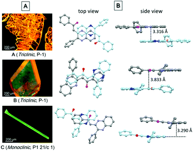 | ||
| Fig. 1 (A) Fluorescence microscopic images of single crystals of polymorphs A–C, and (B) the top and side views of the packing modes in single crystals A–C. | ||
Photophysical properties
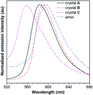
The absorption and emission behavior of each crystal was then systematically investigated. The absorption maximum of the dilute THF solution of PPQE is located at 424 nm with a molar absorptivity of 4.2 × 10⁴ L mol−1 cm−1 (Fig. S2A, ESI†). The UV reflectance spectra of crystals A–C were recorded on a UV-Vis reflectance spectrometer. A similar absorption profile with the same absorption maxima at 424 nm was observed, indicating similar conjugation of the molecule in each crystal (Fig. S2B, ESI†).PL measurement of crystals A–C suggests that they possess different luminescence behaviors (Fig. 2 and Table 1). The THF solution of PPQE emits weakly at 524 nm with a fluorescence quantum yield (ΦF) of 0.2%, representing the emission from the enol form of this ESIPT system. In the aggregated states including crystals and the amorphous solid, the emission from the keto form dominates. Crystals A and B with intermolecular π–π stacking interaction possess emission maxima at 583 nm and 590 nm, respectively. Crystal C with weak intermolecular interaction emits at 558 nm, hypsochromically shifted 25–32 nm compared with that of crystals A and B. The amorphous PPQE obtained from the direct cooling of the melted PPQE in liquid nitrogen, on the other hand, emits faintly at 595 nm with a ΦF of 0.8%. The ΦFs of crystals A, B, and C are 16.0%, 9.4%, and 8.4%, respectively, which are much higher than those of the solution and amorphous solid, suggesting typical crystallization-induced emission characteristics. In the crystalline states, the intramolecular motions are restricted by the intermolecular interactions and spatial constraints, which block the nonradiative decay channels that existed in the solution and amorphous states, and result in significantly enhanced emission. The restriction of intramolecular motion also lowers the reorganization energy in the crystalline state, which leads to decreased Stokes shifts and blue-shifted emission maxima in the crystals compared with that of the amorphous solid of PPQE.
| Entry | λ em (nm) | Φ F (%) | 〈τ〉b (ns) | K r (107 s−1) | K nr (108 s−1) |
|---|---|---|---|---|---|
| a λ ex = 424 nm. b λ ex = 470 nm. c THF solution with a concentration of 10 μM. n.d. = not detectable. d λ ex = 466 nm. Kr = ΦF/〈τ〉 and Knr = 1/〈τ〉 − Kr. | |||||
| Solnc | 524 | 0.2 | n.d. | n.d. | n.d. |
| A | 583 | 16.0 | 2.82 | 5.67 | 2.98 |
| B | 590 | 9.4 | 1.80 | 5.22 | 5.03 |
| C | 558d | 8.4 | 1.01 | 8.32 | 9.07 |
| Amor | 595 | 0.8 | n.d. | n.d. | n.d. |
To gain deep insight into the difference in emission efficiencies of the crystals, their time-resolved PL spectra were recorded and the average fluorescence lifetimes (〈τ〉) of crystals A–C were calculated to be 2.82, 1.80, and 1.01 ns, respectively (Fig. S3, ESI†). The radiative rate constant Kr and the nonradiative rate constant Knr can then be calculated from ΦFs and 〈τ〉. The Knr values increase obviously from 2.98 × 10⁸ s−1 in crystal A to 5.03 × 10⁸ s−1 in crystal B, and then to 9.07 × 10⁸ s−1 in crystal C, accompanied by decreased fluorescence efficiencies. This trend suggests that the nonradiative decay pathways such as intramolecular phenyl ring rotations are more efficient when the intermolecular interactions become weaker in crystal C.
The PL behavior of PPQE was further investigated in THF/water mixtures, considering that PPQE molecules may form nanoaggregates in aqueous mixtures (Fig. S4A, ESI†). When a large amount of poor solvent, water, was added into the THF solution of PPQE, the emission peak gradually redshifts and the fluorescence intensity increases. Moreover, the time-dependent PL spectra of its 99 vol% aqueous mixture suggest that the emission intensity is rapidly increased upon aging while the emission profile remains unchanged, indicating the crystal formation process in the mixed solvent (Fig. S4B, ESI†).
Furthermore, DFT calculations of the highest occupied molecular orbitals (HOMOs) and lowest unoccupied molecular orbitals (LUMOs) based on the ground state molecular configuration of crystals A–C are conducted and the structure–property relationship can be summarized for the different polymorphs of PPQE (Fig. S5, ESI†). The electron densities are mainly located on the dihydroquinoxaline heterocyclics and the neighboring intramolecular hydrogen bond-linked six-membered rings, and these crystals possess similar energy band gaps, revealing that the crystals share similar conjugation, in accordance with the UV-vis reflectance spectra analysis. The emission of crystals A and B is redshifted compared with that of crystal C because of the obvious intermolecular π–π interaction in crystals A and B, while no strong intermolecular interaction exists in crystal C.
Raman spectra analysis
To reveal the difference in intramolecular motions of each crystal, Raman spectroscopy was used to sensitively detect the motion modes. It is proved by theoretical and experimental investigations that the AIE phenomenon can be attributed to the restriction of intramolecular motions.66 In resonance Raman spectra of AIE compounds, the ring rotation motion modes located at the low-frequency region below 100 cm−1 are generally hypsochromically shifted to the higher wavenumber region during aggregation, accompanied by a fluorescence enhancement, indicating the restriction of such rotations.67 As shown in Fig. 3, in the Raman spectra of crystals A–C and the amorphous solid of PPQE, the peaks at the low frequency region are gradually hypsochromically shifted from the amorphous state to crystal C, then to crystal B and crystal A, although the original mode at ∼70 cm−1 still exists, suggesting the restriction of intramolecular motions in the same order. The intermolecular interactions and spatial constraints are also strengthened in the same order, which inhibits the nonradiative decay and enhances the emission efficiency. This trend agrees well with the theoretical predications.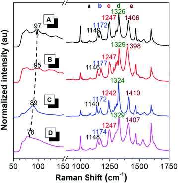 | ||
| Fig. 3 Raman spectra of (A) crystal A, (B) crystal B, (C) crystal C, and (D) the amorphous state of PPQE. | ||
Furthermore, the representative Raman peak position and the relative intensities of each polymorph are unique and reproducible. As shown in the long wavenumber region of Fig. 3, crystals A–C and the amorphous state of PPQE generally possess eight main peaks, the exact peak position of the five representative distinguishable peaks and their corresponding intramolecular motion modes are summarized in Table S3 (ESI†). For example, peak a of crystals A–C associated with the swing between hydrogen atoms and the dihydroquinoxaline ring is located at 1149, 1146, and 1140 cm−1, respectively; while peak e of crystals A–C corresponding to the stretching vibration of the α-carbonyl ethylene group is located at 1406, 1398, and 1410 cm−1, respectively. Besides the repeatable peak location of the Raman spectra of each polymorph, their peak intensity ratios also differ from each other. For example, the peak intensity of peak d is generally higher than that of peak e in the Raman spectra of crystals A and C, while this is opposite in the spectra of crystal B. Hence, the Raman spectrum can be utilized as a simple, convenient, reliable, and in situ method to identify the crystal form of microcrystals by simply comparing the Raman spectrum of the known crystals, instead of the tedious single crystal XRD analysis.
Fluorescence visualization of crystal transformation
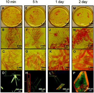
During crystal preparation, an interesting spontaneous crystal transformation was observed from needle-shaped crystal C to bulk crystal B. As shown in Fig. 4A–D, in the saturated warm acetonitrile solution of PPQE, a large amount of needle-shaped crystals with greenish yellow emission are formed after 10 min upon cooling to room temperature. After 5 h, even without external stimuli, a spontaneous transformation from the needle-shaped crystals to bulk crystals with orange emission is observed at room temperature (Fig. 4E–H). In the highlighted rod-like crystal in Fig. 4H, the emission color gradually changes from greenish yellow to orange, indicating a transition state. After 1 day, the majority of needle-shaped crystals have been transformed to bulk crystals (Fig. 4I–L). The transformation can be completed in 2 days without any needle-shaped crystal observed in the solvent system (Fig. 4M–P). Such observations reveal that the crystal formation and transformation of PPQE obeys the Ostwald rule that it is not the most stable but the less stable polymorph that crystallizes first.68–70 The crystal-induced emission property of PPQE, the dark solution background, and the different emission colors of its polymorphs enable the capture of the detailed transition state and real-time monitoring of the crystal transformation process by a fluorescence microscope. The XRD patterns of the initial needle-shaped crystal and the final bulk crystal were compared with the simulated XRD patterns from the three single crystal structures, proving that the needle-shaped crystal and bulk crystal are crystal C and crystal B, respectively (Fig. S6D and E, ESI†). Similarly, in situ transformation from crystal C to crystal B is also observed from the acetone/t-butanol mixed solution. The fast cooling rate is the key issue to form crystal C first, otherwise crystal B is directly formed from the solution by slow cooling and solvent evaporation.Crystal transformation from crystal A to crystal B was also realized by placing crystal A into a saturated acetonitrile solution of PPQE for 2 days (Fig. S7, ESI†). Since the emission color and shape of crystals A and B are difficult to distinguish, the Raman spectrum is used to monitor the transition process and identify the crystals. The five representative peaks in the Raman spectrum of crystal A located at 1149, 1172, 1247, 1326, and 1406 cm−1 have converted to 1146, 1176, 1247, 1329, and 1399 cm−1 after aging, corresponding to the peak values of crystal B in Table S3 (ESI†), suggesting that crystal A has partially transformed into crystal B. These two crystal transformation processes indicate that crystals A and C are kinetically stable crystals, while crystal B is thermodynamically stable.
To understand the single crystal transformations, theoretical calculations of the phenyl ring rotation energy barriers were conducted (Fig. 5). Among the molecular conformations of these three polymorphs, the main differences are the torsion angles θ1 (C9–C10–C11–C12) and θ2 (N2–C7–C17–C18). From the rotational energy barrier calculation (Fig. 5, inset), the difference of θ2 in these three polymorphs is much larger than that of θ1, hence θ2 plays a dominant role in the configuration stability. The optimized θ2 with minimum potential energy is −42°. The molecular configuration in crystal B with the least deviation (θ2 = −47.2°) enjoys the highest stability. Meanwhile, the molecular configurations in crystals A and C show large deviations from the optimal θ2, and are less stable. Their relative energies are 1.29 kcal mol−1 (crystal A) and 0.34 kcal mol−1 (crystal C) higher than that of crystal B, respectively.
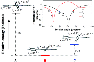 | ||
| Fig. 5 Relative total energies of conformation A, B, and C. Inset: Rotational energy barrier obtained by rotating θ1 and θ2 in the optimized conformation. | ||
Fluorescence visualization of crystal formation processes
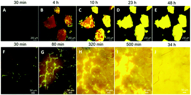
Taking advantage of the faintly emissive solution and amorphous state of PPQE and its emissive crystals, we have successfully demonstrated real-time monitoring of the crystal formation processes from both the amorphous state and the solution state. The glass-like amorphous solid with a deep red appearance and weak emission was freshly prepared by cooling the molten PPQE sample in liquid nitrogen. After 4 h, dark orange emission is observed under a fluorescence microscope, and bright yellow emission emerges in some regions, indicating the formation of crystals (Fig. 6A and B). The emissive region gradually spreads and eventually covers the whole block in 2 days (Fig. 6C–E). The large emission contrast of the amorphous state and crystalline state enables detailed observation (Fig. 6F–J), and the time-dependent fluorescence images reveal that the crystallization first occurs at the cracks of the amorphous block, and then expands to the circumjacent area and finally to the whole block, accompanied by emission enhancement (Video S1, ESI†). The fluorescence quantum yield of the tested sample is gradually increased from 0.8% to 8.5% after 48 h. The freshly prepared amorphous PPQE and the final yellow emissive sample are characterized by XRD (Fig. S6F and G, ESI†) and the pattern of the newly formed crystal perfectly matches the simulated XRD pattern of crystal A. The relatively broad peak indicates that the crystal size is rather small. Raman spectra analysis also suggests that the amorphous solid has gradually transformed into crystal A (Fig. S8, ESI†). Although the Raman spectra of crystal A and the amorphous state of PPQE are quite similar, small shifts of peak b (from 1174 to 1172 cm−1), d (from 1329 to 1326 cm−1), and e (from 1407 to 1406 cm−1) are observed from the Raman spectra of the original amorphous state to that of the yellow emissive sample. Most importantly, in the short wavenumber region below 150 cm−1, the peak at 78 cm−1 in the spectrum of the amorphous sample has split and shifted to 100 cm−1, corresponding to the spectrum of crystal A. The DSC analysis of the amorphous sample (Fig. S9, ESI†) suggested a glass transition temperature (Tg) of PPQE at 26 °C, indicating that the molecular motion and rearrangement might occur at the condensed phase near room temperature.In order to observe the crystal growth process in solution, a saturated acetone/t-butanol mixed solution of PPQE was prepared to slow down the solvent evaporation rate and enable visualization of the fast crystallization process on a glass substrate (Fig. S10A–E and Video S2, ESI†). The crystal growth process in a small amount of solution on a glass substrate is highly dependent on the solvent system and evaporation rate. Upon solvent evaporation, emissive dots emerge quickly, which then gradually grow by absorbing the nearby solution and form new crystal branches (Fig. S10F–J and Video S3, ESI†).
Scratch-induced polymorph formation
Last but not least, a fast scratch induced multiple types of crystal formation and alignment was observed when the saturated acetone/t-butanol solution droplet of PPQE on a glass surface was scratched with a syringe needle. As shown in Fig. 7, two parallel crystal lines are formed along the scratching trajectory after a few minutes. The left line is composed of thin crystal sheets with orange-yellow emission, and the right line is mainly composed of needle-shaped crystals with similar length and greenish yellow emission. The in situ Raman analysis of these two crystal lines has proved that the crystal sheets are crystal A and the needle-like crystals are crystal C (Fig. S11, ESI†). The five representative peaks are located at 1149, 1172, 1247, 1327, and 1408 cm−1 for the sheet-like crystal, and 1141, 1172, 1242, 1325, and 1410 cm−1 for the needle-shaped crystal, corresponding to the standard peak values of crystal A and crystal C, respectively. The mechanical shearing force should be responsible for the crystal line formation. Scratching the contact surface of the glass can generate defects which may reduce the nucleation barrier and promote the crystallization. There are two possible contact points with different contact area and pressure between the syringe needle and the glass substrate, which might cause the formation of different crystals.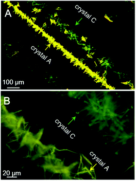 | ||
| Fig. 7 Fluorescence microscopic images of assembled crystal lines induced by scratching with a needle in a saturated acetone/t-butanol mixed solution of PPQE during a solvent evaporation process. | ||
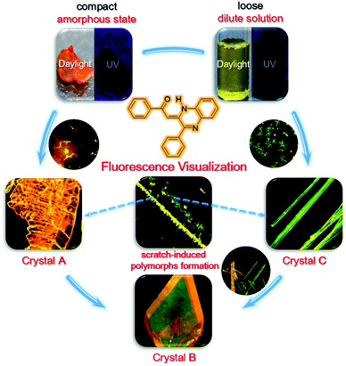
The above-mentioned crystal formation and transformation processes are summarized in Fig. 8. When the initial state of PPQE is an amorphous state where the molecules are compact and the intermolecular distance is small, the quickly formed kinetically stable crystal A with the short intermolecular distance and strongest π–π intermolecular interaction among the three polymorphs directly forms. This is in agreement with the fact that single crystal A is difficult to obtain from various solutions, except for highly concentrated DMSO solution. When the initial state of PPQE is a dilute solution where the intermolecular distance is large, the kinetically stable crystal C without obvious π–π stacking interaction is quickly formed. Single crystal C can be generated quickly in a large variety of solvent systems, especially when the solvent evaporation is accelerated. Both crystals A and C can be spontaneously transformed into the thermodynamically stable crystal B with the lowest energy level, the optimized molecular configuration and good stability in saturated solution at room temperature, because the glass transition temperature of PPQE is near room temperature. Furthermore, the kinetically stable crystals A and C can both be induced to form and align rapidly by applying a mechanical shearing force. Most importantly, the different luminescence behaviors of the solution, amorphous state, and each polymorph of PPQE enable the direct visualization of such crystal formation and transformation processes under a fluorescence microscope.
Conclusions
In summary, PPQE with unique crystal-induced emission features and its three polymorphs A–C are reported. Because of the different intermolecular packing modes, these three single crystals possess varied emission color and efficiency. Increasing the intermolecular interaction in the crystals leads to reduction of non-radiative decay and hence increases the emission efficiency. The kinetically stable crystals A and C are favored to form rapidly from highly concentrated state and dilute solutions, respectively, in accordance with the Ostwald rule. They can both spontaneously be converted into the thermodynamically stable crystal B in a saturated solution at room temperature. The faintly emissive solution and amorphous state of PPQE and the emissive polymorphs enable a high-contrast phase boundary and elimination of the background fluorescence interference, which is crucial for the fluorescence visualization. The CIE attributes of PPQE and the three polymorphs with distinct emission behaviors enable the fluorescence monitoring of crystal formation processes from both the amorphous state and solution state, as well as the single crystal transformation, which can also reveal the mysterious intermediates of such phase transition processes. Interestingly, a mechanical shearing force can induce the formation and alignment of crystals A and C simultaneously on a glass substrate. Furthermore, the facile characterization of the crystal form by Raman analysis has also facilitated the study of the intermediate state or identification of the microcrystals, which is difficult to realize by traditional crystal characterization methods, demonstrating a promising approach for crystal analysis. It is anticipated that this real-time, on-site, nondestructive fluorescence imaging approach can serve as a powerful and convenient tool for crystal analysis, providing detailed and valuable information about the crystal formation and transformation processes.Experimental section
Materials and instruments
Liquid bromine, trimethylamine, and trans-1,2-dibenzoylethylene were purchased from Energy Chemical Ltd; o-phenylenediamine was purchased from J&K Scientific Ltd. All the commercially available reactants and reagents were used as received without further purification. Dibenzoylacetylene was prepared from trans-diphenacylidene according to the literature,71 and PPQE was synthesized from dibenzoylacetylene and o-phenylenediamine according to the reported procedure.63 UV-vis absorption and photoluminescence spectra were recorded on a SHIMADZU UV-2600 spectrophotometer and HORIBA Fluoromax-4 spectrofluorometer, respectively. The UV-vis reflectance spectra were carried out on an Ocean Optics DH-2000 optical fiber spectrometer. The absolute fluorescence quantum yields were measured on a Hamamatsu Absolute Quantum Yield Spectrometer C11347. The time-resolved fluorescence spectra were measured on a Hamamatsu Compact Fluorescence Lifetime Spectrometer C11367. The differential Scanning Calorimetry curve was recorded on a Netzsch DSC 204F1 Phoenix under nitrogen atmosphere at a heating rate of 10 K min−1. The Raman spectra were recorded on a Horiba Jobin Yvon LabRam Aramis Raman spectrometer with a laser of 632.8 nm. The fluorescence microscope images were taken using a Mshot MF30 epifluorescence microscope with the excitation wavelength range of 420–485 nm. Powder X-ray diffraction data were recorded on an X'pert Pro PANalytical X-ray diffractometer with an angle range of 5–50°. Single crystal X-ray diffraction data were collected at 100 K on a Bruker-Nonius Smart Apex CCD diffractometer. Simulated X-ray diffraction patterns were calculated from single crystal structures of polymorphs. Theoretical calculations were performed with the Gaussian 09 program package at the level of B3LYP/6-31g(d,p).72 The single point energies of crystals A–C were calculated on the basis of crystal structures. Then the electron density contours of the HOMOs and LUMOs for crystals A–C were simulated by Gauss View software. The rotational energy barrier was determined through the energy of the resulting geometry after rotating the corresponding torsion angle from the optimized configuration.Conflicts of interest
There are no conflicts to declare.Acknowledgements
This work was partially supported by the National Basic Research Program of China (973 Program; 2013CB834701), the National Science Foundation of China (21404041, 21490573 and 21490574), the Natural Science Foundation of Guangdong Province (2016A030306045 and 2016A030312002), the Innovation and Technology Commission of Hong Kong (ITC-CNERC14SC01).Notes and references
- T. Anzai, M. Kawauchi, T. Kawauchi and J. Kumaki, J. Phys. Chem. B, 2015, 119, 338–347 CrossRef CAS PubMed.
- V. J. Hall and G. J. Simpson, J. Am. Chem. Soc., 2010, 132, 13598–13599 CrossRef CAS PubMed.
- G. Liu, J. Liu, H. Sun, X. Zheng, Y. Liu, X. Li, H. Qi, X. Bai, K. A. Jackson and X. Tao, J. Am. Chem. Soc., 2015, 137, 4972–4975 CrossRef CAS PubMed.
- M. H. Nielsen, S. Aloni and J. J. D. Yoreo, Science, 2014, 345, 1158–1162 CrossRef CAS PubMed.
- B. D. Hamilton, J. M. Ha, M. A. Hillmyer and M. D. Ward, Acc. Chem. Res., 2012, 45, 414–423 CrossRef CAS PubMed.
- M. D. Ward, Chem. Rev., 2001, 101, 1697–1726 CrossRef CAS PubMed.
- Y. Diao, M. E. Helgeson, A. S. Myerson, T. A. Hatton, P. S. Doyle and B. L. Trout, J. Am. Chem. Soc., 2011, 133, 3756–3759 CrossRef CAS PubMed.
- D. Khamar, J. Zeglinski, D. Mealey and Å. C. Rasmuson, J. Am. Chem. Soc., 2014, 136, 11664–11673 CrossRef CAS PubMed.
- Y. Lei, Q. Liao, H. Fu and J. Yao, J. Phys. Chem. C, 2009, 113, 10038–10043 CAS.
- L. Y. Pfund, C. P. Price, J. J. Frick and A. J. Matzger, J. Am. Chem. Soc., 2015, 137, 871–875 CrossRef CAS PubMed.
- X. Gu, J. Yao, G. Zhang, Y. Yan, C. Zhang, Q. Peng, Q. Liao, Y. Wu, Z. Xu, Y. Zhao, H. Fu and D. Zhang, Adv. Funct. Mater., 2012, 22, 4862–4872 CrossRef CAS.
- K. Wang, H. Zhang, S. Chen, G. Yang, J. Zhang, W. Tian, Z. Su and Y. Wang, Adv. Mater., 2014, 26, 6168–6173 CrossRef CAS PubMed.
- Y. Dong, B. Xu, J. Zhang, X. Tan, L. Wang, J. Chen, H. Lv, S. Wen, B. Li, L. Ye, B. Zou and W. Tian, Angew. Chem., Int. Ed., 2012, 124, 10940–10943 CrossRef.
- M. S. Yuan, D. E. Wang, P. Xue, W. Wang, J. C. Wang, Q. Tu, Z. Liu, Y. Liu, Y. Zhang and J. Wang, Chem. Mater., 2014, 26, 2467–2477 CrossRef CAS.
- Y. Li, J. Qiu, J. Miao, Z. Zhang, X. Yang and G. Sun, J. Phys. Chem. C, 2015, 119, 18602–18610 CAS.
- G. Zhang, J. Lu, M. Sabat and C. L. Fraser, J. Am. Chem. Soc., 2010, 132, 2160–2162 CrossRef CAS PubMed.
- L. Yu, Acc. Chem. Res., 2010, 43, 1257–1266 CrossRef CAS PubMed.
- A. Arjona-Esteban, J. Krumrain, A. Liess, M. Stolte, L. Huang, D. Schmidt, V. Stepanenko, M. Gsänger, D. Hertel, K. Meerholz and F. Würthner, J. Am. Chem. Soc., 2015, 137, 13524–13534 CrossRef CAS PubMed.
- D. Maddileti, B. Swapna and A. Nangia, Cryst. Growth Des., 2015, 15, 1745–1756 CAS.
- D. K. Bučar, R. W. Lancaster and J. Bernstein, Angew. Chem., Int. Ed., 2015, 54, 6972–6993 CrossRef PubMed.
- J. Y. Kim, T. Yasuda, Y. S. Yang, N. Matsumoto and C. Adachi, Chem. Commun., 2014, 50, 1523–1526 RSC.
- A. Troisi and G. Orlandi, J. Phys. Chem. B, 2005, 109, 1849–1856 CrossRef CAS PubMed.
- D. J. Gundlach, T. N. Jackson, D. G. Schlom and S. F. Nelson, Appl. Phys. Lett., 1999, 74, 3302–3304 CrossRef CAS.
- H. Kageyama, H. Ohishi, M. Tanaka, Y. Ohmori and Y. Shirota, Adv. Funct. Mater., 2009, 19, 3948–3955 CrossRef CAS.
- H. Jiang, X. Yang, Z. Cui, Y. Liu, H. Li, W. Hu, Y. Liu and D. Zhu, Appl. Phys. Lett., 2007, 91, 3505–3508 Search PubMed.
- R. Pfattner, M. Mas-Torrent, I. Bilotti, A. Brillante, S. Milita, F. Liscio, F. Biscarini, T. Marszalek, J. Ulanski, A. Nosal, M. Gazicki-Lipman, M. Leufgen, G. Schmidt, L. W. Molenkamp, V. Laukhin, J. Veciana and C. Rovira, Adv. Mater., 2010, 22, 4198–4203 CrossRef CAS PubMed.
- M. Brinkmann, G. Gadret, M. Muccini, C. Taliani, N. Masciocchi and A. Sironi, J. Am. Chem. Soc., 2000, 122, 5147–5157 CrossRef CAS.
- M. Cölle, R. E. Dinnebier and W. Brütting, Chem. Commun., 2002, 2908–2909 RSC.
- T. Siegrist, C. Kloc, R. A. Laudise, H. E. Katz and R. C. Haddon, Adv. Mater., 1998, 10, 379–382 CrossRef CAS.
- G. Horowitz, B. Bachet, A. Yassar, P. Lang, F. Demanze, J. L. Fave and F. Garnier, Chem. Mater., 1995, 7, 1337–1341 CrossRef CAS.
- T. Kawamichi, T. Haneda, M. Kawano and M. Fujita, Nature, 2009, 461, 633–635 CrossRef CAS PubMed.
- M. Garcia-Garibay, Angew. Chem., Int. Ed., 2007, 46, 8945–8947 CrossRef CAS PubMed.
- A. J. L. Ayitou, K. Flynn, S. Jockusch, S. Khan and M. Garcia-Garibay, J. Am. Chem. Soc., 2016, 138, 2644–2648 CrossRef CAS PubMed.
- Y. Jiang, M. Kellermeier, D. Gebauer, Z. Lu, R. Rosenberg, A. Moise, M. Przybylski and H. Colfen, Nat. Commun., 2017 DOI:10.1038/ncomms15933.
- M. A. Malwitz, S. H. Lim, R. L. White-Morris, D. M. Pham, M. M. Olmstead and A. L. Balch, J. Am. Chem. Soc., 2012, 134, 10885–10893 CrossRef CAS PubMed.
- Y. Xu, S. Wu, X. Liu, L. Zhang and J. Lu, Cryst. Res. Technol., 2017, 52, 1600379 CrossRef.
- T. Seki, K. Sakurada, M. Muromoto and H. Ito, Chem. Sci., 2015, 6, 1491–1497 RSC.
- Y. Liu, H. Gao, H. Xu, F. Ren and G. Ren, Org. Process Res. Dev., 2016, 20, 1559–1565 CrossRef CAS.
- B. P. Krishnan and K. M. Sureshan, J. Am. Chem. Soc., 2015, 137, 1692–1696 CrossRef CAS PubMed.
- M. Chalfie, Y. Tu, G. Euskirchen, W. W. Ward and D. C. Prasher, Science, 1994, 263, 802–805 CAS.
- B. N. G. Giepmans, S. R. Adams, M. H. Ellisman and R. Y. Tsien, Science, 2006, 312, 217–219 CrossRef CAS PubMed.
- L. Schermelleh, R. Heintzmann and H. Leonhardt, J. Cell Biol., 2010, 190, 165–175 CrossRef CAS PubMed.
- K. I. Willig, S. O. Rizzoli, V. Westphal, R. Jahn and S. W. Hell, Nature, 2006, 440, 935–939 CrossRef CAS PubMed.
- E. Betzig, G. H. Patterson, R. Sougrat, O. W. Lindwasser, S. Olenych, J. S. Bonifacino, M. W. Davidson, J. Lippincott-Schwartz and H. F. Hess, Science, 2006, 313, 1642–1645 CrossRef CAS PubMed.
- M. J. Rust, M. Bates and X. W. Zhuang, Nat. Methods, 2006, 3, 793–796 CrossRef CAS PubMed.
- F. Ito, Y. Suzuki, J. Fujimori, T. Sagawa, M. Hara, T. Seki, R. Yasukuni and M. L. Chapelle, Sci. Rep., 2016, 6, 22918–22923 CrossRef CAS PubMed.
- J. Luo, Z. Xie, J. W. Y. Lam, L. Cheng, H. Chen, C. Qiu, H. S. Kwok, X. Zhan, Y. Liu, D. Zhu and B. Z. Tang, Chem. Commun., 2001, 1740–1741 RSC.
- J. Mei, N. L. C. Leung, R. T. K. Kwok, J. W. Y. Lam and B. Z. Tang, Chem. Rev., 2015, 115, 11718–11940 CrossRef CAS PubMed.
- J. Liang, B. Z. Tang and B. Liu, Chem. Soc. Rev., 2015, 44, 2798–2811 RSC.
- J. Li, Y. Li, C. Y. K. Chan, R. T. K. Kwok, H. Li, P. Zrazhevskiy, X. Gao, J. Z. Sun, A. Qin and B. Z. Tang, Angew. Chem., Int. Ed., 2014, 53, 13518–13522 CrossRef CAS PubMed.
- X. Ye, Y. Liu, Y. Lv, G. Liu, X. Zheng, Q. Han, K. A. Jackson and X. Tao, Angew. Chem., Int. Ed., 2015, 27, 8087–8091 CrossRef.
- D. Yan and D. G. Evans, Mater. Horiz., 2014, 1, 46–57 RSC.
- Y. Dong, J. W. Y. Lam, A. Qin, Z. Li, J. Sun, H. H. Y. Sung, I. D. Williams and B. Z. Tang, Chem. Commun., 2007, 40–42 RSC.
- D. Yan, H. Yang, Q. Meng, H. Lin and M. Wei, Adv. Funct. Mater., 2014, 24, 587–594 CrossRef CAS.
- D. Yan, A. Delori, G. O. Lloyd, T. Friščić, G. M. Day, W. Jones, J. Lu, M. Wei, D. G. Evans and X. Duan, Angew. Chem., 2011, 123, 12691–12694 CrossRef.
- J. Yang, Z. Ren, B. Chen, M. Fang, Z. Zhao, B. Z. Tang, Q. Peng and Z. Li, J. Mater. Chem. C, 2017, 5, 9242–9246 RSC.
- J. Yang, L. Li, Y. Yu, Z. Ren, Q. Peng, S. Ye, Q. Li and Z. Li, Mater. Chem. Front., 2017, 1, 91–99 RSC.
- S. Ohtani, M. Gon, K. Tanaka and Y. Chujo, Chem. – Eur. J., 2017, 23, 11827–11833 CrossRef CAS PubMed.
- Y. Li, X. Yang, J. Miao, Z. Zhang and G. Sun, CrystEngComm, 2016, 18, 2098–2104 RSC.
- P. Galer, R. C. Korošec, M. Vidmar and B. Šket, J. Am. Chem. Soc., 2014, 136, 7383–7394 CrossRef CAS PubMed.
- A. Babenysheva, N. Lisovskaya, I. Belevich and N. Y. Lisovenko, Pharm. Chem. J., 2006, 40, 611–613 CrossRef CAS.
- D. Zhang, Y. Yang, M. Gao, W. Shu, L. Wu, Y. Zhu and A. Wu, Tetrahedron, 2013, 69, 1849–1856 CrossRef CAS.
- M. I. Ansari, R. Shankar, M. K. Hussain, R. Kant, P. R. Maulik, K. R. Kumar and K. Hajela, J. Heterocycl. Chem., 2011, 48, 1336–1341 CrossRef CAS.
- T. Mutai, H. Tomoda, T. Ohkawa, Y. Yabe and K. Araki, Angew. Chem., Int. Ed., 2008, 49, 9664–9666 CrossRef.
- H. Lin, X. Chang, D. Yan, W. H. Fang and G. Cui, Chem. Sci., 2017, 8, 2086–2090 RSC.
- J. Mei, Y. Hong, J. W. Y. Lam, A. Qin, Y. Tang and B. Z. Tang, Adv. Mater., 2014, 26, 5429–5479 CrossRef CAS PubMed.
- T. Zhang, H. Ma, Y. Niu, W. Li, D. Wang, Q. Peng, Z. Shuai and W. Liang, J. Phys. Chem. C, 2015, 119, 5040–5047 CAS.
- S. Y. Chung, Y. M. Kim, J. G. Kim and Y. J. Kim, Nat. Phys., 2009, 5, 68–73 CrossRef CAS.
- D. Cavallo, D. Mileva, G. Portale, L. Zhang, L. Balzano, G. C. Alfonso and R. Androsch, ACS Macro Lett., 2012, 1, 1051–1055 CrossRef CAS.
- A. Levin, T. O. Mason, L. A. Abramovich, A. K. Buell, G. Meisl, C. Galvagnion, Y. Bram, S. A. Stratford, C. M. Dobson, T. P. J. Knowles and E. Gazit, Nat. Commun., 2014, 5, 5219–5226 CrossRef CAS PubMed.
- J. J. Zhang and G. B. Schuster, J. Am. Chem. Soc., 1989, 111, 7149–7155 CrossRef CAS.
- A. D. Becke, J. Chem. Phys., 1993, 98, 5648–5652 CrossRef CAS.
Footnotes |
| † Electronic supplementary information (ESI) available: Preparation of polymorphs and amorphous samples of PPQE, single crystal data for single crystals A–C, single crystal transformation process, the absorption and emission spectra, XRD, Raman spectra for single crystals A–C and amorphous samples, Raman peaks and their corresponding motion modes, fluorescence images of the crystal formation process, calculated molecular orbital amplitude plots and energy levels. CCDC 1500090–1500092. For ESI and crystallographic data in CIF or other electronic format see DOI: 10.1039/c7qm00435d |
| ‡ These authors contributed equally. |
| This journal is © the Partner Organisations 2018 |


