Fabrication of Bi2S3/ZnO heterostructures: an excellent photocatalyst for visible-light-driven hydrogen generation and photoelectrochemical properties†
Susmita
Bera
,
Srabanti
Ghosh
 * and
Rajendra N.
Basu
*
CSIR-Central Glass and Ceramic Research Institute, 196, Raja S.C. Mullick Road, Kolkata – 700032, India. E-mail: ghosh.srabanti@gmail.com; rnbasu@cgcri.res.in
First published on 27th November 2017
Abstract
Fabrication of heterostructures is considered as one of the effective strategies to improve photocatalytic performance for organic pollutant degradation and hydrogen production under solar light irradiation. Here, Bi2S3/ZnO heterostructures with a flower-like architecture have been successfully synthesized by a facile in situ generation method. The as-synthesized Bi2S3/ZnO heterostructures showed enhanced visible-light absorption and charge separation efficiency of photoinduced electron–hole pairs. This heterojunction exhibits 3 fold enhancement in organic pollutant degradation and 2.7 fold enhancement in photocatalytic hydrogen generation under visible irradiation compared to rod-shaped Bi2S3. The high current gain (ca. 8.79) and low photocorrosion in photoelectrochemical water splitting reveal the superior photocatalytic activity of the heterojunction under visible light. The superior photocatalytic activities are attributed to the synergetic effects of ZnO nanoparticles and rod-shaped Bi2S3 in the Bi2S3/ZnO heterostructures, which result in fast separation and slow recombination of photoinduced electron–hole pairs. The reusability and stability of the photocatalysts has been checked by recycling experiments. X-ray diffraction and scanning electron microscopy reveal that the structure and morphology of the heterostructures remain unchanged after photocatalytic cycling tests. The visible light active catalysts have potential for efficient solar light harvesting and overall water splitting. This work demonstrates the potential use of heterostructures as a highly efficient photocatalyst for dye degradation and hydrogen production under visible light irradiation.
Introduction
The challenges of environmental pollution and renewable energy production are both highly active areas of scientific research.1,2 Visible light-induced photocatalysis is an effective clean approach for water splitting to generate clean solar fuels and converting solar energy to chemical energy.3,4 On the other hand, water purification and environmental protection pose an equally daunting challenge.5,6 Oxide-based semiconductors have been utilized as active photocatalysts in various applications such as photochemical degradation of organic contaminants, photochemical water splitting to produce hydrogen and photoelectrochemical cells.7–9 Titanium dioxide (TiO2) is one of the most popular photocatalysts and possesses high catalytic activity, low cost and non-toxicity.10,11 However, TiO2 can only absorb UV radiation (4% of the total solar irradiation) due to its wide band gap and low charge separation efficiency, which makes it unsuitable for visible light active photocatalysis.12,13 Moreover, TiO2 doping with C, N, B, or S or modification with metal nanoparticles (Au, Pt, Ag) results in plasmon-induced enhanced visible light absorption; however, the high cost and low environmental stability of noble-metal-doped TiO2 restricts its economic potential.14–16 Another semiconductor nanocrystal, zinc oxide (ZnO), having a direct band gap of 3.3 eV and a large excitation binding energy has been widely tested for phtotocatalytic applications.17–19 Moreover, ZnO has some advantageous properties over TiO2 such as high electron mobility due to its electronic structure, room temperature luminescence etc.18,19 In this regard, the loading of multiple catalysts or secondary semiconductors can improve the catalytic efficiency of ZnO via the formation of heterojunctions.20,21 This stimulated our interest in designing a coupled heterojunction with ZnO to improve solar light absorption in the visible region.Significant efforts have been made on the fabrication of semiconductor-based heterostructures such as ZnO/TiO2,22 Bi2S3/TiO223,24 and CdS/TiO225etc., which show potential applications in water splitting and organic pollutant degradation. In fact, high charge separation has been achieved via coupling of a large band gap semiconductor with a smaller one forming a heterojunction, which in turn enhances the photocatalytic efficiency by decreasing the recombination rate of the photogenerated electron–hole pairs.26,27 In the case of a heterojunction, charge carriers are generated in one semiconductor and then vectorially transfer to the other material allowing for long lived electron hole pairs at the interface and are able to produce a potential gradient within the catalyst.5 The presence of multiple active sites within the heterostructures can provide a high surface area for the decomposition of organic pollutant molecules at the surface of the catalysts.28 For example, TiO2-based hybrid heterojunctions demonstrated high catalytic activity due to surface tunnelling of electrons between the surfaces of the semiconducting components of the heterostructure.29 Until now, most of the studies have been focused on the hybridization of TiO2 with semiconductors to improve the photocatalytic efficiency under visible light.29–33 In this regard, few reports have been published on the modification of ZnO nanostructures with other semiconductors such as ZnO/TiO2,34 CdS/ZnO35etc. for improved visible light-driven photocatalysis.
On the other hand, low band gap semiconductors such as sulphides, nitrides, graphitic carbon nitrides, oxynitrides, chalcogenides etc., have been widely investigated to construct visible light active photocatalysts.36–39 Among these, bismuth sulphide (Bi2S3), a low band gap metal sulphide (1.3 eV), has shown absorption in the visible region and has been considered a potential candidate for photocatalytic applications.40 However, the rapid recombination of photo-induced electrons and holes limits the catalytic application of Bi2S3 under visible light. Recently, a series of Bi2S3-based heterostructures such as MoS2/Bi2S3,41 Bi2S3/CdS,42 Bi2S3/Bi2WO6,43 Bi2S3/In2S3,44 Bi2S3/BiVO4,45 Bi2S3/(BiO)2CO346etc., have been developed to improve the light absorption and charge separation efficiency. Recently, Bi2S3/g-C3N4 heterostructures exhibited high catalytic performance for organic dye (Rhodamine B) degradation, but the apparent kinetic rate was very low.47 MoS2/Bi2S3 and Bi2S3/In2S3 heterojunctions showed high catalytic activity for organic pollutant degradation but no report on hydrogen generation is available to date. Notably, semiconductor-based heterostructures are effective catalysts for water oxidation as the photogenerated electrons and holes on the surface of heterostructures have the potential to react at the surface active site. Thus, the excited electrons reduce the water to form hydrogen and the holes oxidize the water to generate oxygen.48 The Bi2S3/CdS heterostructures displayed photocatalytic hydrogen generation under visible light irradiation but the hydrogen evolution rate is low.42 Recently, Wang et al.49 have used Z-scheme CdTe–Bi2S3 heterojunctions for photoelectrochemical performance. Hence, Bi2S3-based heterojunctions have been extensively utilized for organic dye degradation but photocatalytic hydrogen generation has not been tested yet. Herein, Bi2S3 with a narrow band gap has been integrated with ZnO nanoparticles to fabricate visible light active heterostructures. Various characterization techniques such as XRD, SEM, TEM and FTIR have been employed for characterizing the structure, morphology and optical properties of the heterostructures. To the best of our knowledge, for the first time, we studied the photocatalytic performance and photoelectrochemical properties of Bi2S3/ZnO for hydrogen generation under visible light.
Experimental section
Materials
Bismuth nitrate pentahydrate (Bi(NO3)3·5H2O, 99.99%), L-cysteine hydro-chloride (99.99%), mercaptosuccinic acid (MSA, 99%), ethylenediaminetetraacetic acid disodium salt (EDTA-Na, 99%), methanol were procured from Sigma Aldrich, USA. For the in situ generation of ZnO, zinc acetate dehydrate (Zn(CH3COO)2·2H2O, 98%) and sodium hydroxide (NaOH, 98%) were procured from Merck, Germany.Synthesis of Bi2S3 nanostructures
In a typical synthesis, 0.5 mmol of ethylenediaminetetraacetic acid disodium salt (EDTA-Na) was dissolved in 100 mL of distilled water and stirred for 10 minutes. Then 0.4 mmol of Bi(NO3)3 was mixed and the solution mixture was ultrasonicated until the solution became transparent. After that, 0.6 mmol of L-cysteine hydrochloride was added to the solution. Finally, the solution was transferred into a 100 mL Teflon-lined autoclave with a stainless steel shell and heated at 180 °C for 16 h. The Bi2S3 was collected and centrifuged, washed several times with distilled water and finally air-dried overnight at 50 °C for further characterization. Similarly, Bi2S3 nanostructures were also prepared using mercaptosuccinic acid as a sulphur source.50 The effect of sulphur source concentration (0.6, 1.2, 2.4 mmol) and different reaction times (10, 16, 24 h) to follow the growth mechanism of Bi2S3 nanostructure formation has been studied in detail.Synthesis of Bi2S3/ZnO heterostructures
In order to develop a coupled heterostructure of Bi2S3/ZnO, a facile in situ generation via co-precipitation technique has been employed using ethanol as a solvent.17 Briefly, 20 mL of 4 mmol zinc acetate dehydrate solution was heated at 70 °C for 30 min. Then a fixed amount of prepared Bi2S3 powder (1 mg mL−1) was added and mixed thoroughly. In the next step, 20 mL of 4 mmol sodium hydroxide solution prepared at 70 °C in ethanol was added slowly and the mixture was hydrolyzed for 2 h at 60 °C to obtain ZnO NPs with average diameters of ∼5 nm. The pure semiconductors and heterostructures are presented as L-Bi2S3, L-Bi2S3/ZnO (using L-cysteine hydro-chloride as a source of sulphur) and M-Bi2S3, M-Bi2S3/ZnO (using MSA as a source of sulphur). To understand the growth mechanism of Bi2S3, extensive experimental analyses were performed for varying reaction times, metal salt to surfactant ratios and sulphur sources.Instrumentation
The crystalline phase of Bi2S3 and the heterostructures was investigated by XRD (Philips X’Pert, The Netherlands) within the 2θ range of 10° to 80° at a slow scan rate of 1° min−1 with Cu Kα radiation (at 40 kV and 40 mA). The structural morphology and EDS was recorded by Field Emission Scanning Electron Microscopy (LEO. 430i, Carl-Zeiss, Sigma). Transmission Electron Microscopy (TEM) images and the corresponding selected area electron diffraction (SAED) patterns were obtained on Tecnai G2 30ST (FEI) operating at 300 kV. The XPS study was performed using a PHI 5000 Versa Probe II spectrophotometer (Physical Electronics Inc., USA) with a monochromatized Al Kα (∼1486.6 eV) X-ray beam of size ∼100 μm. The samples were prepared in pallet form and the surfaces were sputtered with a 2 kV rastered Ar+ ion beam for one minute to clean the surface. The thermal stability of the bare Bi2S3 and heterojunction was investigated using thermogravimetric analysis (TGA) apparatus (NETZSCH, STA 449 F3, Jupiter). The test was carried out in air with a heating rate of 10 °C min−1 from 100 °C to 900 °C. The porosity and specific surface area of the samples were determined through nitrogen adsorption at 200 °C on the basis of the BET equation using a Quantachrome, FL-33426. The UV-visible absorption spectra of the ethanolic solutions containing Bi2S3, ZnO and Bi2S3/ZnO were recorded using a Shimadzu, UV-3600 spectrophotometer. The hydrogen evolution was measured by online gas chromatography using a YL Instrument, 6500GC system with a thermoconductive detector. The photoelectrochemical measurements have been tested using a galvanostat–potentiostat (PGSTAT302N, Autolab, The Netherlands) with a standard three-electrode cell and Pt wire as a counter electrode and saturated Ag/AgCl as a reference electrode. The working electrode was a thin film of as-prepared material on glassy carbon. The photocatalytic I–V characteristics have been measured using simulated illumination (60 mW cm−2) by a white light source.Photocatalytic test
L-Bi2S3, L-Bi2S3/ZnO, M-Bi2S3 and M-Bi2S3/ZnO have been tested for dye degradation using methyl orange (MO) as a model pollutant. It is a representative of hazardous azo dyes. The photodegradation of MO (initial concentration C0 = 0.3 × 10⁻⁴ M) was carried out within a quartz cell reactor containing 50 mL model solution with a concentration of 1 mg mL−1 under UV and visible lamps. A Xe-arc lamp (250 W) with an incident beam intensity of 100 mW cm−2 (Oriel, Irvine, CA) was used as a light source for visible irradiation and a 395 nm cutoff filter was used. For a control experiment, bare L-Bi2S3 and M-Bi2S3 have been studied separately under similar reaction conditions. The appropriate amount of aliquots was collected from the reactor at successive time intervals. The percentage degradation (% DE) of MO was determined using the following equation: | (1) |
Photocatalytic hydrogen generation
To study the hydrogen generation, the online gas chromatography method was used where the area under the Gaussian peak gives the amount of H2 evolved. The H2 production through water splitting was performed in a closed reactor in the presence of methanol solution with saturated argon media and vigorous stirring. For this experiment, a 25 volume% methanol solution was used at room temperature.51 Here, methanol acts as a sacrificial agent and use of methanol is very much advantageous compared to other alcohols because it reduces the formation of more carbon-based sub-products being the simplest organic molecule and also accelerates the main intermediate (free radical) formation process.51 Here we report H2 generation up to 3 h.Results and discussion
Structural characterization
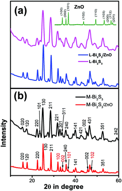
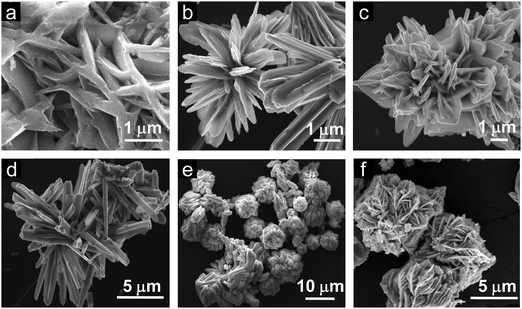
XRD was carried out to study the crystalline phase of the as-prepared materials. Fig. 1a and b show the X-ray diffraction (XRD) patterns of L-Bi2S3, L-Bi2S3/ZnO, M-Bi2S3 and M-Bi2S3/ZnO. The X-ray patterns displayed narrow and sharp diffraction peaks, indicating the high crystallinity of the prepared samples. The strong peaks at 2θ values of 15.54, 17.41, 22.21, 23.57, 24.92, 28.43, and 31.71 correspond to characteristic diffraction from the (020), (120), (220), (101), (130), (211) and (221) planes of pure Bi2S3 respectively (JCPDS card no. 17-0320).47 The diffraction peaks of ZnO at 2θ values of 31.76, 34.00 and 36.56 correspond to the (100), (002) and (101) planes indicating the wurtzite hexagonal phase of ZnO (JCPDS card no. 36-1451).52 The XRD pattern of the pure ZnO nanoparticles is shown in the inset of Fig. 1a which indicates that the nanoparticles are highly crystalline in nature. Therefore, the XRD patterns of the heterostructures reveal the presence of wurtzite ZnO within orthorhombic Bi2S3. Moreover, the presence of all the characteristic peaks of Bi2S3 and no additional peak in the heterostructures confirms the purity of Bi2S3/ZnO. Moreover, no remarkable changes were observed in the diffraction peak position and intensity of Bi2S3/ZnO at longer hydrothermal reaction times indicating the formation of stable orthorhombic Bi2S3 (Fig. S1, ESI†).The morphology and growth of Bi2S3 and Bi2S3/ZnO were investigated by field emission scanning electron microscopy (FESEM). Fig. 2a–c illustrates the assembled growth of Bi2S3 rods with increasing reaction time. It is clear from Fig. 2a that when the hydrothermal reaction proceeds for 10 h, the formation of rod-like structures is obtained which are completely overlapped. At 16 h, distinct rods with an average length of ∼3.81 μm (Fig. 2b) are formed which are connected with each other and radiated from a centre.
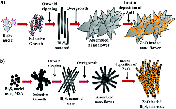
With further increase in the reaction time up to 24 h, the rods are more assembled and interestingly form a lotus flower-like morphology (Fig. 2c). This may happen due to over growth of Bi2S3 nuclei in the same direction.42 In addition, the metal salt to surfactant ratio has been varied to investigate the role of the surfactant as a morphology controlling factor. Fig. 2d–f display Bi2S3 synthesized at three different concentrations of surfactant at 16 h keeping all other conditions similar.
When the metal salt![[thin space (1/6-em)]](https://www.rsc.org/images/entities/char_2009.gif) :
:![[thin space (1/6-em)]](https://www.rsc.org/images/entities/char_2009.gif) L-cysteine ratio is 1
L-cysteine ratio is 1![[thin space (1/6-em)]](https://www.rsc.org/images/entities/char_2009.gif) :
:![[thin space (1/6-em)]](https://www.rsc.org/images/entities/char_2009.gif) 1.5, it can be observed that irregularly distributed rod-shaped structures of average length ∼4.7 μm are formed (Fig. 2d). In contrast, at 1
1.5, it can be observed that irregularly distributed rod-shaped structures of average length ∼4.7 μm are formed (Fig. 2d). In contrast, at 1![[thin space (1/6-em)]](https://www.rsc.org/images/entities/char_2009.gif) :
:![[thin space (1/6-em)]](https://www.rsc.org/images/entities/char_2009.gif) 3, the assembled morphology (length ∼5.5 μm) consists of rods that have been formed with a bunched-like structure.
3, the assembled morphology (length ∼5.5 μm) consists of rods that have been formed with a bunched-like structure.
Moreover, at a higher concentration of L-cysteine (1![[thin space (1/6-em)]](https://www.rsc.org/images/entities/char_2009.gif) :
:![[thin space (1/6-em)]](https://www.rsc.org/images/entities/char_2009.gif) 6 ratio), more assembled structures have been formed. Fig. 2e displays Bi2S3 superstructures of diameter ∼8 μm which are built of two-dimensional nanosheets. Hence, this highly assembled morphology is useful to provide more active sites in photocatalytic applications. In general, an assembled 1D morphology is more suitable for photocatalytic applications having a large surface to volume ratio, synergistic interactions as the long lengths of the nanorods will contact each other, and multiple functionalities.53
6 ratio), more assembled structures have been formed. Fig. 2e displays Bi2S3 superstructures of diameter ∼8 μm which are built of two-dimensional nanosheets. Hence, this highly assembled morphology is useful to provide more active sites in photocatalytic applications. In general, an assembled 1D morphology is more suitable for photocatalytic applications having a large surface to volume ratio, synergistic interactions as the long lengths of the nanorods will contact each other, and multiple functionalities.53
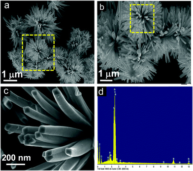
Another kind of Bi2S3 nanostructure has been developed using mercaptosuccinic acid as a structure controlling agent. Fig. 3a–c illustrates the FESEM images of pure Bi2S3 at different magnifications, and clearly indicates solid rods radiated from a common centre and stacked uniformly to form a nanoflower-like morphology.
At high magnification, it has been clearly observed that the nanoflowers consist of solid rods of length ∼500 nm with the square edge of the sides at 60 to 70 nm (Fig. 3c). To investigate the elemental composition, X-ray energy-dispersive spectrometry (EDS) was carried out on the Bi2S3 nanoflowers. Fig. 3d indicates the coexistence of Bi and S elements on the rod-shaped structures. However, the presence of Al and Si signals originated from the glass substrate.
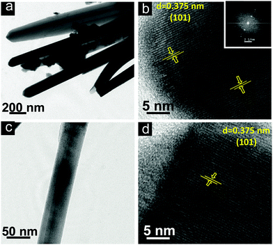
Additionally, the detailed structural and crystalline nature of the as-prepared Bi2S3 and Bi2S3/ZnO has been investigated through TEM and HRTEM images (Fig. 4). The TEM images (Fig. 4a and c) clearly reveal the uniform 1D structures of L-Bi2S3 and M-Bi2S3 and are well consistent with the FESEM images. The interplanar spacing of 0.375 nm reveals the characteristic (101) plane of Bi2S3 (Fig. 4b and d).54 Therefore, the preferential growth of Bi2S3 rods occurred along the (101) direction. The calculated size of the bare ZnO NPs is in the range of 5 nm as determined from the TEM image (Fig. S2, ESI†).
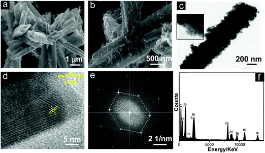
The microscopic images of the L-Bi2S3/ZnO heterostructures are displayed in Fig. 5. It can clearly be seen from the SEM images (Fig. 5a and b) that the spherical ZnO NPs have been formed uniformly deposited on the L-Bi2S3 surface. A further detailed study on the morphology of the L-Bi2S3/ZnO heterostructures has been performed through the TEM images. Fig. 5c clearly shows the rough surface of the rod-shaped L-Bi2S3 due to deposition of spherical hexagonal ZnO nanoparticles over the surface. The HRTEM image of L-Bi2S3/ZnO reveals its highly crystalline nature having a lattice spacing of about 0.33 nm related to the (130) plane of Bi2S3 (Fig. 5d).55 The SAED pattern depicts the highly crystalline hexagonal structure of Bi2S3 (Fig. 5e). For further analysis of chemical compositions and the elemental distribution, EDS was carried out (Fig. 5f) where strong signals of Bi, S, O and Zn also confirm the formation of Bi2S3/ZnO heterostructures.
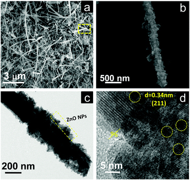
The morphology and crystalline nature of the heterostructures using M-Bi2S3 was further investigated using FESEM and TEM images. Fig. 6a shows the in situ generation of ZnO NPs on the rod-shaped M-Bi2S3 structures. It is evident that the assembled nanoflower-like structures are totally transformed into a nanofibre-based network after the formation of ZnO NPs. This is probably due to the strong interaction between ZnO and the surface ligand (MSA) of Bi2S3 which is responsible for the formation of the self-assembled nanoflower-like morphology. The FESEM image also illustrates that the single rod-shaped structure of Bi2S3 is completely covered by small ZnO NPs (Fig. 6b). Fig. 6c shows that the M-Bi2S3/ZnO rod-like nanostructures are covered with smaller nanoparticles which is consistent with the FESEM image (Fig. 6a and b) and the cross fringes in the HRTEM image indicate the crystallinity of the heterostructures with a lattice spacing value of 0.30 nm related to the (211) plane of Bi2S3 (Fig. 6d).56 Owing to the highly crystalline nature of Bi2S3, it is difficult to observe crystal fringes of ZnO within the heterostructures.
The growth of bare Bi2S3 and its heterostructures can be explained on the basis of coordination interaction between Bi3+ and the surfactant. In the hydrothermal synthesis of the Bi2S3 nanostructures and in situ generation method for heterojunction formation, the following reactions may be involved:
| Bi(NO3)3·5H2O → Bi3+ + 3NO3− + 5H2O | (2) |
| L-Cys + Bi(NO3)3 → Bi(III)–L-Cys | (3) |
| MSA + Bi(NO3)3 → Bi(III)–MSA complex | (4) |
 | (5) |
 | (6) |
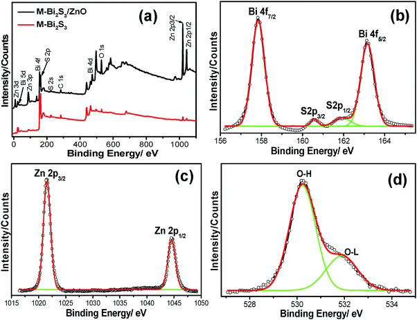
X-ray photon spectroscopy (XPS) was carried out to further elucidate the chemical compositions as well as the oxidation states of the pure semiconductor and heterostructures. The overall XPS spectra (Fig. 7a) indicate the presence of strong peaks of Bi, S, Zn, O and C. Here, the 1S peak of C acts as a reference point coming from the background.
The strong peaks at binding energies of 157.84 eV and 163.16 eV with typical spin orbit doublet splitting of 5.32 eV can be assigned to the binding energy of Bi 4f7/2 and Bi 4f5/2 respectively, closely matched with the Bi3+ in Bi2S3 (Fig. 7b).60 The peaks found between Bi 4f7/2 and Bi 4f5/2 at 161.83 eV and 160.56 eV correspond to S 2p1/2 and S 2p3/2 (1.27 eV), which indicates the existence of S2− within Bi2S3.42 Moreover, after the heterojunction formation, the blue shift of the binding energy for Bi 4f7/2 (∼0.3 eV), Bi 4f5/2 (∼0.27 eV) and S (∼0.19 eV) indicates the strong interaction between Bi2S3 and ZnO followed by the formation of a heterojunction. In addition, the strong oxidation peaks located at 1021.9 eV and 1045.1 eV of Zn 2p3/2 and 2p1/2 respectively (Fig. 7c) suggest the Zn2+ state of ZnO.49 It is also observed that the binding energy of pure ZnO shifts towards a lower value of 0.23 eV after forming a heterojunction. Fig. 7d exhibits the asymmetric profile of O 1s which can be fitted to two symmetrical peaks at 530.2 and 531.72 eV, indicating the presence of two different kinds of O species in the sample. The peaks at 531.72 eV and 530.2 eV should be associated with the lattice oxygen (OL) of ZnO and chemisorbed oxygen (OH) by the surface.61 Thus, the XPS spectra suggest the co-existence of Bi2S3 and ZnO within the heterostructures.
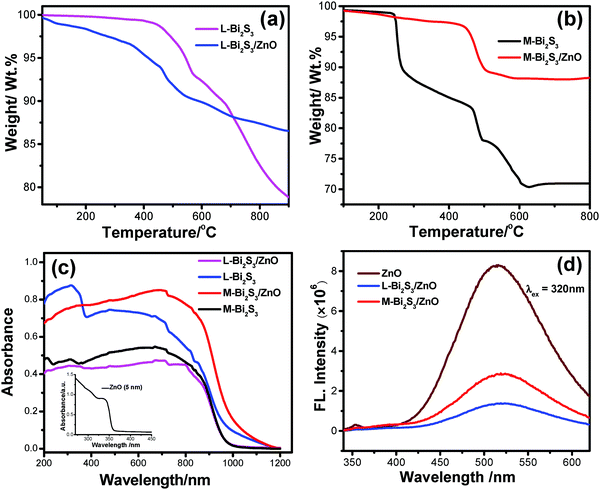
Thermo gravimetric analysis (TGA) was carried out to determine the loading of ZnO NPs after in situ deposition as well as the thermal stability of the heterostructure. The loading of ZnO calculated from the TGA curves is found to be 10% and 15% for L-Bi2S3 and M-Bi2S3 respectively (Fig. 8a and b). The initial mass losses in the range of 220 °C to 230 °C originate from the removal of adsorbed O2 and water molecules. The further mass loss above 380 °C is mainly attributed to the decomposition of Bi2S3 into Bi metal.
Notably, after 440 °C, the pure Bi2S3 curve is fairly stable whereas the Bi2S3/ZnO heterostructures are unstable and indicate a strong weight loss above 478 °C which implies the formation of ZnO.42 The porous structure of the pure semiconductor as well as the heterostructures was studied by the nitrogen adsorption desorption isotherm method. The specific surface areas calculated by the BJH method are 3.13 m2 g−1 and 9.53 m2 g−1 for the pure M-Bi2S3 and M-Bi2S3/ZnO heterostructures, respectively. This indicates that the specific BET surface area is increased when the heterojunction is formed which may be useful for photocatalytic applications.56 The hysteresis loop present in the BET curve (Fig. S3, ESI†) suggests the type II pattern of the semiconductor heterostructures. Hence, incorporation of ZnO nanoparticles effectively generates porosity and active surface sites within the heterostructure.
The optical properties of the pure semiconductor and semiconductor heterostructures have been evaluated by diffuse reflectance and photoluminescence (PL) spectroscopy. Fig. 8c shows the diffuse reflectance spectroscopy of the bare semiconductors and heterostructures where both the L-Bi2S3/ZnO and M-Bi2S3/ZnO heterostructures demonstrated broad absorption in the visible range that extends up to the near IR range. For the bare ZnO, the onset of light absorption is in the UV region with a band gap of ∼3.37 eV. The light absorption of the Bi2S3/ZnO heterostructures increases in the visible region compared to bare ZnO or Bi2S3 indicating that heterostructures are useful for efficient solar light harvesting applications. The photoluminescence spectra of ZnO display an emission peak at ∼514 nm upon excitation to 320 nm, as shown in Fig. 8d. The intensity of the emission peak lowered significantly to 519 nm and 517 nm when L-Bi2S3 and M-Bi2S3 attached to the ZnO NPs. Thus, the quenching in emission intensity (65.5% for M-Bi2S3/ZnO and 83.25% for L-Bi2S3/ZnO) for the heterostructures (Fig. 8d) indicates the strong electronic interaction and improved charge carrier separation efficiency.17
Photocatalytic MO degradation
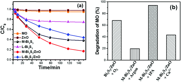
The photocatalytic activity has been studied under visible light using methyl orange (MO) as a model pollutant. It is well known that MO is a very stable dye which is resistant to self-photo degradation. Fig. 9a clearly shows the degradation of MO in the presence of Bi2S3 and Bi2S3/ZnO under visible light irradiation. The M-Bi2S3/ZnO heterostructures exhibit significantly enhanced photocatalytic activity as compared with bare M-Bi2S3 and L-Bi2S3. Bare L-Bi2S3 has negligible photocatalytic activity (26%) but bare M-Bi2S3 shows high activity (63%). In contrast, the photodegradation efficiency of MO reached 82% for M-Bi2S3/ZnO and 55% for L-Bi2S3/ZnO after 150 min of visible light irradiation (Fig. 9a), indicating that heterostructures possess superior photocatalytic activity. The photocatalytic activity of the M-Bi2S3/ZnO heterostructures is ∼8.6 times higher compared to bare M-Bi2S3.The enhanced photocatalytic activity of heterostructures can be achieved due to strong absorption in the visible range with high surface area of the assembled structure.62 As evident from the TGA data, loading of ZnO NPs on the M-Bi2S3 nanofibres may create more catalytic centres within the heterostructure and thereby show high catalytic activity. The enhanced catalytic activity of M-Bi2S3/ZnO may be associated with the multiple reflections and scattering of light within the interconnected rods which results in enhanced light absorption as reflected in the absorption spectra (Fig. 8c).28 Similarly, L-Bi2S3/ZnO demonstrated higher catalytic activity in comparison with bare L-Bi2S3. The photocatalytic activity under UV light irradiation was also studied where M-Bi2S3/ZnO degrades only 48% of MO concentration (Fig. S4, ESI†).
Possible reactions involved in photocatalytic dye degradation are given below.
| Bi2S3/ZnO → hVB+ + eCB− | (7) |
| O2 + e− → O2˙− | (8) |
| O2˙− + h+ → HO2˙ | (9) |
| 2H2O + O2˙− → 4OH˙ | (10) |
In order to investigate the photocatalytic mechanism of the heterostructure-based catalysts, a further study has been conducted in the presence of sacrificial agents and the contribution of excess electron–holes (Cu2+, isopropanol and saturated argon media) (Fig. 9b).62 Semiconductors react with photoinduced electrons and holes from water to form various reactive species including O2˙− and OH˙.63 Herein, Cu2+ was used to understand the role of excess electrons as it reacts with electrons very quickly and converts into Cu+. The remarkable change of MO degradation in the presence of 2 × 10⁻⁶ M Cu2+ (it changes 68% to 43%) is presented in Fig. 9b after 6 h visible light irradiation. This suggests a role of electrons during the photocatalytic reaction. In order to confirm the role of O2˙−, a photodegradation experiment has been performed under argon saturated atmosphere. In general, the argon-saturated inert medium may suppress the O2˙− radical production which may be the possible reason for inhibiting the degradation of MO by M-Bi2S3/ZnO.62 It only degrades 20% of MO after 4 h of visible light irradiation. Thus, it can be concluded that oxygen has a crucial role in the photocatalytic reaction. Moreover, photocatalysis has been performed in the presence of 0.1 M isopropanol (acts as a hole scavenger) and oxygen to investigate the role of photoexcited holes in the photocatalytic reactions. The decomposition kinetics of MO increased up to 94% in the presence of isopropanol which clearly indicates the role of holes in the photodegradation of MO.
Photocatalytic H2 generation
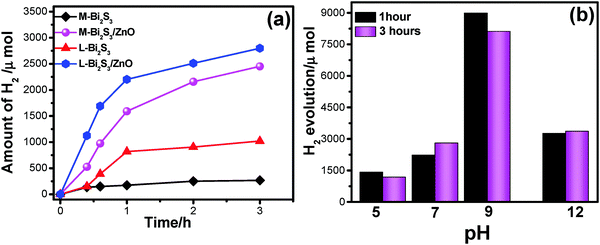
Fig. 10a shows photocatalytic H2 generation by Bi2S3 and Bi2S3/ZnO heterostructures via water splitting using 25 volume% of methanol solution as a sacrificial agent. In general, the semiconductors with more negative CB can reduce water efficiently, and thus increase the hydrogen production rate. Herein, a relatively low band gap semiconductor, Bi2S3, acts as a recombination centre for ZnO and the reduction process occurs at the ZnO surface. The H2 generation enhanced with the increase in irradiation time. The amount of H2 production is higher for heterostructures, L-Bi2S3/ZnO (2791 μmol). For comparison, the H2 evolution activity has been investigated for bare semiconductors L-Bi2S3 and M-Bi2S3 under visible light irradiation. The heterojunction shows 2.74-fold enhancement in hydrogen generation compared to L-Bi2S3 (1020 μmol). The H2 generation for M-Bi2S3 and M-Bi2S3/ZnO is 263 μmol and 2450 μmol respectively. In contrast to dye degradation, L-Bi2S3/ZnO shows superior performance for photocatalytic hydrogen generation in comparison to M-Bi2S3/ZnO.The exact reason is not clear to us but the enhanced catalytic activity may be associated with the assembled morphology of L-Bi2S3/ZnO which leads to intimate contact between metal sulphide and the zinc oxide NPs. The three-dimensional interconnected assembled structure may also facilitate the transport of photogenerated electrons and holes to the binding sites; thereby water oxidation occurred in the presence of a sacrificial agent which is consistent with the literature report.64 Moreover, both the heterostructures may provide facile electron transfer compared with bare semiconductors which can effectively enhance the hydrogen generation.65
Furthermore, the effect of pH on the photocatalytic hydrogen evolution process has been studied to optimize the reaction conditions. Fig. 10b illustrates that higher activity for hydrogen evolution is achieved at pH 9, ∼8089 μmol, whereas under low pH conditions, i.e. acidic conditions, it generates only 1159 μmol due to protonation of the photocatalyst in acidic solution.65 Generally under acidic conditions the driving force for hydrogen generation decreases as the redox potential of H+/H2 becomes more negative. On the other hand, a highly alkaline medium is also not preferable for hydrogen evolution because of insufficient protons.66
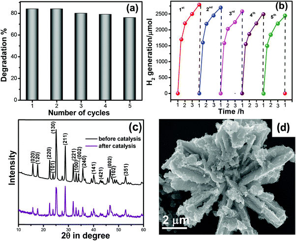
In view of practical applications, reusability and stability of photocatalysts is an important parameter. Here, we checked the recycling of M-Bi2S3/ZnO up to 5 successive cycles and the result is displayed in Fig. 11a, which reveals nearly 10% loss in MO degradation. In hydrogen generation, a recycling experiment of L-Bi2S3/ZnO has been performed up to the 5th cycle displayed in Fig. 11b. After the 5th cycle, no remarkable decline was found in the hydrogen evolution rate. Therefore, it can be concluded that the M-Bi2S3/ZnO and L-Bi2S3/ZnO heterostructures are stable and reusable visible light active photocatalysts for organic pollutant degradation as well as for hydrogen generation. To ensure the structural stability and morphology of the catalyst, XRD and FESEM were re-examined before and after catalytic reactions. As shown in Fig. 11c, the XRD patterns of the ZnO decorated Bi2S3 heterostructures almost remain the same and all the characteristic peaks are present. The FESEM image of the heterostructures reflects a similar kind of morphology after the photocatalytic reaction. Thus the semiconductor-based coupled heterostructures are stable under long visible light irradiation and represent a fruitful approach for solar light energy harvesting.
Photoelectrochemical performance
In order to investigate the photoelectrochemical activity of the Bi2S3/ZnO heterostructures, it is important to find out the band edge potential of both Bi2S3 and ZnO as band edge potentials play a crucial role in determining the migration routes of photo-generated electrons and holes. Additionally, photocatalytic activity directly depends on optical absorption, phase structure, morphology and separation efficiency of photo-generated charge carriers. The valence band (VB) and conduction band (CB) of both the semiconductors were calculated using the following empirical equations,42| EVB = x − Efe + 1/2Eg | (11) |
| ECB = x − Efe − 1/2Eg | (12) |
| Catalyst | Dark current (Idark) (mA cm−2) | Photo current (Ilight) (mA cm−2) | Photo current gain Ilight/Idark |
|---|---|---|---|
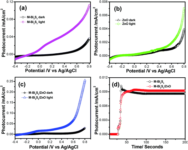
| M-Bi2S3 | 0.039 | 0.112 | 2.88 |
| ZnO | 0.004 | 0.007 | 1.79 |
| M-Bi2S3/ZnO | 0.029 | 0.255 | 8.79 |
This result implies that the M-Bi2S3/ZnO heterostructures show higher photoelectrochemical activity and a photo current gain which is ca. 3.05 times increased compared to the single component M-Bi2S3. Notably, bare Bi2S3 also shows high photocurrent but due to fast recombination problems its photocurrent gain reduces. Thereby, the introduction of ZnO with Bi2S3 enhances light absorption and charge separation efficiency. The stability of pure semiconductor as well as heterostructures was investigated by the chronoamperometry method under light illumination for 200 seconds (Fig. 12d).69 In the presence of light, a certain change in current density is displayed for M-Bi2S3 whereas a gradually increasing tendency is exhibited for the coupled system M-Bi2S3/ZnO because of a charge transfer mechanism.17 As the photogenerated electrons migrate through the CB, more and more electrons are gathered at the active surface site and gradually increase the current density. Remarkably, Fig. 12d shows the long time i–t response (up to 600 s) and the current density remains almost stable which indicates that the catalysts are durable against photocorrosion. Hence, M-Bi2S3/ZnO shows enhanced photoelectrochemical activity compared to bare Bi2S3 and ZnO.
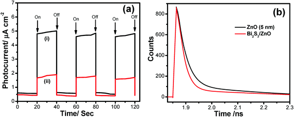
The photocurrent for Bi2S3 and the heterostructures shows 7.39 and 8.06 fold enhancement in current density compared with dark conditions at a voltage of 1.0 V respectively (Fig. S5, ESI†). This enhancement in current density may happen due to enhanced charge carrier separation in the presence of light irradiation. The linear nature of the I–V plot indicates the good ohomic contact between the semiconductor and the ITO-coated glass substrate which is a good sign for device applications.70 When light falls on the catalyst surface, excess photocarriers are generated which leads to charge separation and electrons are efficiently transferred to the electrode when voltage is applied.71 The fluorescence decay curves at an excitation wavelength of 400 nm for ZnO and Bi2S3/ZnO have been examined to investigate the decay dynamics of the heterostructures.
It is observed that the photocurrent is higher for heterostructures than single semiconductors. These charge carrier separation phenomena also enhance the mobility of electrons. The on/off photocurrent has been measured at 20 second intervals at a bias voltage 500 mV (Fig. 13a), which exhibits two distinct states – one is a high current state when the light is on and the other is a low current state while the light is off. This time-dependent response of the Bi2S3/ZnO-coupled system is preferable for optoelectronic device applications. In the photocatalytic process, super oxide radicals and holes have a crucial role in organic dye degradation which has been previously confirmed by lots of tests. Hence, the photo-excited electron and holes are responsible for generating these free radicals. Moreover, the enhanced charge separation have been studied via picosecond resolved time correlated single photon counting (TCSPC). Fig. 13b shows a decay curve of ZnO with an average life time of 4.34 ns. Interestingly, it decreases to 0.338 ns when Bi2S3 is attached with ZnO. From this sharp decrease in average life time, it can be concluded that fast electron transfer happens within the heterostructures through the CB of ZnO to Bi2S3.17 This charge transfer reduces the recombination rate, which can also be understood from the PL study, confirming that more electrons may participate for photocatalytic water splitting and H2 generation (Table 2).
| Sample | Excitation wavelength (nm) | Detection wavelength (nm) | τ 1 (ns) | τ 2 (ns) | τ avg (ns) |
|---|---|---|---|---|---|
| ZnO NPs | 400 | 500 | 0.82 (51.8%) | 29.30 (7.5%) | 4.42 |
| Bi2S3/ZnO | 400 | 500 | 0.25 (42.0%) | 5.02 (7.9%) | 0.338 |
Depending on the above results and discussion, a probable mechanism of photocatalytic activity can be described as follows. In the presence of solar light, both the semiconductors absorb light and the electrons in the VB get excited up to a higher potential of −1.53 eV for Bi2S3 and −0.2 eV for ZnO.55 Therefore, the effective charge transfer process proceeds within the semiconductor due to high photon energy.42 Generally, the excited electrons and holes always wish to transfer to the nearest recombination centre. The CB electrons of the Bi2S3 rods can transfer to the CB of the ZnO NPs and simultaneously the excited holes of ZnO can migrate to the Bi2S3 rods and consequently reduce the first recombination process shown in Scheme 2. These photo-generated electrons and holes generate oxidative radicals (in the presence of O2) such as h+, OH˙, and O2˙− by the oxidation of O2 and the reduction of H2O which are mainly responsible for dye degradation. In hydrogen evolution, the sacrificial agent methanol acts as a hole scavenger and generates more OH˙ free radicals and accelerates the H2 production rate. As the band position of Bi2S3 is not suitable for H2 production, it can be concluded that photochemical reactions occur at the ZnO surface and incorporation of a narrow band gap semiconductor helps in charge separation, leading to more efficient activity in H2 generation.69–72 On the other hand, the visible light activity can be explained on the basis of a hole-trapping mechanism which has been explained in the scheme diagram. Therefore, semiconductor heterojunctions are a suitable route for creating more recombination centres and thus increase the life time of electrons as well as reduce the recombination rate.
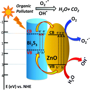 | ||
| Scheme 2 Proposed diagram for the possible band edge energy for charge separation and migration in the Bi2S3/ZnO heterostructures. | ||
Conclusions
In summary, an assembled nanoflower morphology of Bi2S3 decorated with ZnO nanoparticles has been successfully synthesized by a facile in situ deposition method. The strong absorption of Bi2S3/ZnO heterostructures in the visible region and enhanced charge separation in the heterostructures makes them promising candidates for solar light harvesting applications. The experimental results indicate that M-Bi2S3/ZnO demonstrates high catalytic activity for organic pollutant degradation, whereas L-Bi2S3/ZnO shows superior performance for photocatalytic H2 generation through water splitting. The photocatalytic activity of the heterostructures is ∼8.6 times higher compared to bare Bi2S3. The L-Bi2S3/ZnO heterostructures (2791 μmol) exhibit 2.74 fold enhancements in photocatalytic hydrogen generation compared to L-Bi2S3 (1020 μmol) under visible light. Notably, Bi2S3/ZnO demonstrates high photoelectrochemical activity with a photo current density of 0.25 mA cm−2, which is 56% and 97% higher than that of bare M-Bi2S3 and ZnO respectively under similar reaction conditions. The band edge potential of the heterostructures is suitable for sufficient charge separation which causes enhancement in photo current. Hence, the present synthetic methodology can be employed to prepare efficient, low cost heterostructure-based photocatalysts to substitute the common use of noble metal-based catalysts, and Bi2S3/ZnO has potential in environmental remediation and water-splitting applications.Conflicts of interest
There are no conflicts to declare.Acknowledgements
One of the authors (SB) is thankful to Department of Science & Technology (DST), India, for providing an INSPIRE fellowship. Another author (SG) is thankful to the Council of Scientific & Industrial Research (CSIR), India, for providing a CSIR-Senior Research Associateship (Scientists’ Pool Scheme). The authors also wish to thank Dr Sunirmal Jana and Dr Rajat Banerjee of this institute for their help by providing some of the instrumental facilities. The authors acknowledge Director, CSIR-CGCRI for his kind permission to publish the work.References
- M. R. Hoffmann, S. T. Martin, W. Choi and D. W. Bahnemann, Chem. Rev., 1995, 95, 69–96 CrossRef CAS
.
- T. Jafari, E. Moharreri, A. S. Amin, R. Miao, W. Song and S. L. Suib, Molecules, 2016, 21, 900–929 CrossRef PubMed
.
- Z. G. Zou, J. H. Ye, K. Sayama and H. Arakawa, Nature, 2001, 414, 625–627 CrossRef CAS PubMed
.
- D. J. Martin, K. Qiu, S. A. Shevlin, A. D. Handoko, X. Chen, Z. Guo and J. Tang, Angew. Chem., Int. Ed., 2014, 53, 9240–9245 CrossRef CAS PubMed
.
- A. Kudo and Y. Miseki, Chem. Soc. Rev., 2009, 38, 253–278 RSC
.
- S. Ghosh, N. A. Kouame, S. Remita, L. Ramos, F. Goubard, P.-H. Aubert, A. Dazzi, A. Deniset-Besseau and H. Remita, Sci. Rep., 2015, 5, 18002–18011 CrossRef CAS PubMed
.
- T. Hisatomi, J. Kubota and K. Domen, Chem. Soc. Rev., 2014, 43, 7520–7535 RSC
.
- Y. H. Ng, A. Iwase, A. Kudo and R. Amal, J. Phys. Chem. Lett., 2010, 1, 2607–2612 CrossRef CAS
.
- H. Wang, L. Zhang, Z. Chen, J. Hu, S. Li, Z. Wang and J. Liu, Chem. Soc. Rev., 2014, 43, 5234–5244 RSC
.
- A. Fujishima and K. Honda, Nature, 1972, 238, 37–38 CrossRef CAS PubMed
.
- J. Tian, Z. Zhao, A. Kumar, R. I. Boughton and H. Liu, Chem. Soc. Rev., 2014, 43, 6920–6937 RSC
.
- L. Xu, G. A. Sewvandi, S. Uemura, T. Kusunose, S. Nakanishia and Q. Feng, New J. Chem., 2017, 41, 10998–11008 RSC
.
- G. Wang, H. Wang, Y. Ling, Y. Tang, X. Yang, R. C. Fitzmorris, C. Wang, J. Z. Zhang and Y. Li, Nano Lett., 2011, 11, 3026–3033 CrossRef CAS PubMed
.
- J. Virkutyte and R. S. Varma, New J. Chem., 2010, 34, 1094–1096 RSC
.
- M. D. Hernandez-Alonso, F. Fresno, S. Suarez and J. M. Coronado, Energy Environ. Sci., 2009, 2, 1231–1257 CAS
.
- S. Piskunov, O. Lisovski, J. Begens, D. Bocharov, Y. F. Zhukovskii, M. Wessel and E. Spohr, J. Phys. Chem. C, 2015, 119, 8686–18696 Search PubMed
.
- S. Sardar, P. Kar, H. Remita, B. Liu, P. Lemmens, S. K. Pal and S. Ghosh, Sci. Rep., 2015, 5, 17313–17327 CrossRef CAS PubMed
.
- J. Dutta, M. A. Mahmood and S. Baruah, Mater. Chem. Phys., 2011, 130, 531–535 CrossRef
.
- Q. Shen, X. Zhao, S. Zhou, W. Hou and J.-J. Zhu, J. Phys. Chem. C, 2011, 115, 17958–17964 CAS
.
- K. M. Lee, C. W. Lai, K. S. Ngai and J. C. Juan, Water Res., 2016, 88, 428–448 CrossRef CAS PubMed
.
- L. Zhang, L. Du, X. Yu, S. Tan, X. Cai, P. Yang, Y. Gu and W. Mai, ACS Appl. Mater. Interfaces, 2014, 6, 3623–3629 CAS
.
- G. Marci, V. Augugliaro, M. J. López-Muñoz, C. Martin, L. Palmisano, V. Rives, M. Schiavello, R. J. D. Tilley and A. M. Venezia, J. Phys. Chem. B, 2001, 105, 1026–1032 CrossRef CAS
.
- R. Brahimi, Y. Bessekhouad, A. Bouguelia and M. Trari, Catal. Today, 2007, 122, 62–65 CrossRef CAS
.
- S. Boumaza, B. Bellal, A. Boudjemaa and M. Trari, Sol. Energy, 2016, 139, 444–451 CrossRef CAS
.
- N. Qin, Y. Liu, W. Wu, L. Shen, X. Chen, Z. Li and L. Wu, Langmuir, 2015, 31, 1203–1209 CrossRef CAS PubMed
.
- S. J. Jum, G. K. Hyun, A. J. Upendra, W. J. Ji and S. L. Jae, Int. J. Hydrogen Energy, 2008, 33, 5975–5980 CrossRef
.
- S. K. Dutta, S. K. Mehetor and N. Pradhan, J. Phys. Chem. Lett., 2015, 6, 936–944 CrossRef CAS PubMed
.
- X. Li, J. Yu and M. Jaroniec, Chem. Soc. Rev., 2016, 45, 2603–2636 RSC
.
- J. Zhang, G. Xiao, F.-X. Xiao and B. Liu, Mater. Chem. Front., 2017, 1, 231–250 RSC
.
- L. Jing, J. Zhou, J. R. Durrant, J. Tang and D. Liu, Energy Environ. Sci., 2012, 5, 6552–6558 CAS
.
- C. Sotelo-Vazquez, R. Quesada-Cabrera, M. Ling, D. O. Scanlon, A. Kafizas, P. K. Thakur, T.-L. Lee, A. Taylor, G. W. Watson, R. G. Palgrave, J. R. Durrant, C. S. Blackman and I. P. Parkin, Adv. Funct. Mater., 2017, 27, 1605413 CrossRef
.
- S. J. A. Moniz, S. A. Shevlin, X. An, Z.-X. Guo and J. Tang, Chem. – Eur. J., 2014, 20, 15571–15579 CrossRef CAS PubMed
.
- M. Xie, X. Fu, L. Jing, P. Luan, Y. Feng and H. Fu, Adv. Energy Mater., 2013, 4, 1300995 CrossRef
.
- F.-X. Xiao, ACS Appl. Mater. Interfaces, 2012, 4, 7055–7063 CAS
.
- C. Eley, T. Li, F. Liao, S. M. Fairclough, J. M. Smith, G. Smith and S. C. E. Tsang, Angew. Chem., Int. Ed., 2014, 53, 7838–7842 CrossRef CAS PubMed
.
- A. Abdi, A. Denoyelle, N. Commenges-Bernole and M. Trari, Int. J. Hydrogen Energy, 2013, 38, 2070–2078 CrossRef CAS
.
- L. X. Hao, G. Chen, Y. G. Yu, Y. S. Zhou, Z. H. Han and Y. Liu, Int. J. Hydrogen Energy, 2014, 39, 14479–14486 CrossRef CAS
.
- F. Dong, Z. Ni, P. Li and Z. Wu, New J. Chem., 2015, 39, 4737–4744 RSC
.
- Q.-Z. Huang, Y. Xiong, Q. Zhang, H.-C. Yao and Z.-J. Li, Appl. Catal., B, 2017, 209, 514–522 CrossRef CAS
.
- H. He, S. P. Berglund, P. Xiao, W. D. Chemelewski, Y. Zhang and C. B. Mullins, J. Mater. Chem. A, 2013, 1, 12826–12834 CAS
.
- M. Li, J. Wang, P. Zhang, Q. Deng, J. Zhang, K. Jiang, Z. Hu and J. Chu, Sci. Rep., 2017, 7, 42484–42492 CrossRef CAS PubMed
.
- R. P. Panmand, Y. A. Sethi, R. S. Deokar, D. J. Late, H. M. Gholap, J.-O. Baeg and B. B. Kale, RSC Adv., 2016, 6, 23508–23517 RSC
.
- C. Zhang, Y. Zhou, Y. Zhang, S. Zhao, J. Fang and X. Sheng, New J. Chem., 2017, 41, 11089–11096 RSC
.
- J. Zhou, G. Tian, Y. Chen, Y. Shi, C. Tian, K. Pan and H. Fu, Sci. Rep., 2014, 4, 4027–4035 CrossRef PubMed
.
- X. Gao, H. B. Wu, L. Zheng, Y. Zhong, Y. Hu and X. W. Lou, Angew. Chem., Int. Ed., 2014, 53, 5917–5921 CrossRef CAS PubMed
.
- F. Dong, X. Feng, Y. Zhang, C. Gao and Z. Wu, RSC Adv., 2015, 5, 11714–11723 RSC
.
- D. Lu, H. Wang, X. Zhao, K. K. Kondamareddy, J. Ding, C. Li and P. Fang, ACS Sustainable Chem. Eng., 2017, 5, 1436–1445 CrossRef CAS
.
- S. S. Thind, C. C. Mustapic, J. Wen, C. D. Goodwin and A. Chen, New J. Chem., 2017, 41, 10542–10549 RSC
.
- Q. Liu, J. Huan, N. Hao, J. Qian, H. Mao and K. Wang, ACS Appl. Mater. Interfaces, 2017, 9, 18369–18376 CAS
.
- H. Bao, X. Cui, C. M. Li, Y. Gan, J. Zhang and J. Guo, J. Phys. Chem. C, 2007, 111, 12279–12283 CAS
.
- M. G. Mendez-Medrano, E. Kowalska, A. Lehoux, A. Herissan, B. Ohtani, S. Rau, C. Colbeau-Justin, J. L. Rodriguez-Lopez and H. Remita, J. Phys. Chem. C, 2016, 120, 25010–25022 CAS
.
- B. Li, Y. Zhang, R. Du, L. Gan and X. Yu, Langmuir, 2016, 32, 11639–11645 CrossRef CAS PubMed
.
- S. Hernández, V. Cauda, A. Chiodoni, S. Dallorto, A. Sacco, D. Hidalgo, E. Celasco and C. F. Pirri, ACS Appl. Mater. Interfaces, 2014, 6, 12153–12167 Search PubMed
.
- Y. Wang, J. Chen, P. Wang, L. Chen, Y.-B. Chen and L.-M. Wu, J. Phys. Chem. C, 2009, 113, 16009–16014 CAS
.
- S. Khanchandani, S. Kundu, A. Patra and A. K. Ganguli, J. Phys. Chem. C, 2013, 117, 5558–5567 CAS
.
- J. Zhang, L. Zhang, N. Yu, K. Xu, S. Li, H. Wang and J. Liu, RSC Adv., 2015, 5, 75081–75088 RSC
.
- A. Priyam, S. Ghosh, S. C. Bhattacharya and A. Saha, J. Colloid Interface Sci., 2009, 331, 195–201 CrossRef PubMed
.
- S. Ghosh, A. Priyam, S. C. Bhattacharya and A. Saha, J. Fluoresc., 2009, 19, 723–731 CrossRef CAS PubMed
.
- S. Ghosh, M. Ray, M. Das, A. Chakrabarti, A. H. Khan, D. D. Sarma and S. Acharya, Phys. Chem. Chem. Phys., 2014, 16, 5276–5283 RSC
.
- M. Han and J. Jia, J. Power Sources, 2016, 329, 23–30 CrossRef CAS
.
- X. Zhang, J. Qin, Y. Xue, P. Yu, B. Zhang, L. Wang and R. Liu, Sci. Rep., 2014, 4, 4596–4604 CrossRef PubMed
.
- S. Ghosh, N. A. Kouame, L. Ramos, S. Remita, A. Dazzi, A. Deniset-Besseau, P. Beaunier, F. Goubard, P.-H. Aubert and H. Remita, Nat. Mater., 2015, 14, 505–511 CrossRef CAS PubMed
.
- W. Cui, J. Li, F. Dong, Y. Sun, G. Jiang, W. Cen, S. C. Lee and Z. Wu, Environ. Sci. Technol., 2017, 51, 10682–10690 CrossRef CAS PubMed
.
- J. Sun, J. Zhang, M. Zhang, M. Antonietti, X. Fu and X. Wang, Nat. Commun., 2012, 3, 1139 CrossRef
.
- S. Luo, F. Chai, L. Zhang, C. Wang, L. Li, X. Liu and Z. Su, J. Mater. Chem., 2012, 22, 4832–4836 RSC
.
- F. Ozel, E. Aslan, B. Istanbullu, O. Akay and I. H. Patir, Appl. Catal., B, 2016, 198, 67–73 CrossRef CAS
.
- B. Tian and Y. Wu, Appl. Catal., B, 2017, 204, 33–42 CrossRef
.
- C. Liu, Y. Yang, W. Li, J. Li, Y. Li and Q. Chen, Sci. Rep., 2016, 6, 23451–23463 CrossRef CAS PubMed
.
- C. Liu, Y. Yang, W. Li, J. Li, Y. Li and Q. Chen, Int. J. Hydrogen Energy, 2016, 41, 1–9 CrossRef CAS
.
- J. Kundu, S. Khilari and D. Pradhan, ACS Appl. Mater. Interfaces, 2017, 9, 9669–9680 CAS
.
- X. Zhang, Y. Liu, G. Zhang, Y. Wang, H. Zhang and F. Huang, ACS Appl. Mater. Interfaces, 2015, 7, 4442–4448 CAS
.
- Y.-Q. Zhang, S. Li and B.-P. Zhang, RSC Adv., 2016, 6, 103215–103223 RSC
.
Footnote |
| † Electronic supplementary information (ESI) available. See DOI: 10.1039/c7nj03424e |
| This journal is © The Royal Society of Chemistry and the Centre National de la Recherche Scientifique 2018 |

