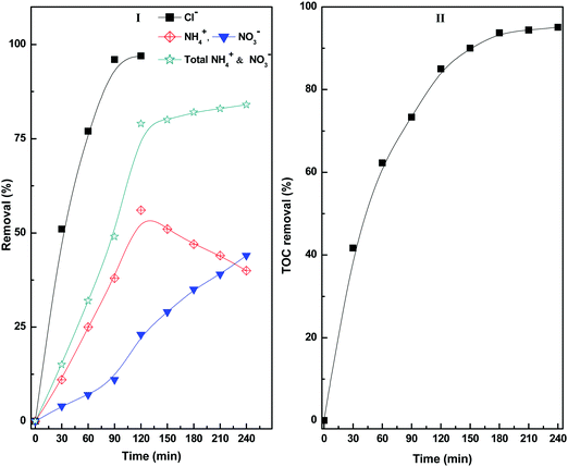
Visible light-assisted photocatalytic mineralization of diuron pesticide using novel type II CuS/Bi2W2O9 heterojunctions with a hierarchical microspherical structure†
Yagna Prakash
Bhoi
a,
Chinmaya
Behera
a,
Dibyananda
Majhi
a,
Sk. Md.
Equeenuddin
b and
B. G.
Mishra
 *a
*a
aDepartment of Chemistry, National Institute of Technology, Rourkela-769008, Odisha, India. E-mail: brajam@nitrkl.ac.in
bDepartment of Earth and Atmospheric Sciences, National Institute of Technology, Rourkela-769008, Odisha, India
First published on 20th November 2017
Abstract
In this study, a series of CuS/Bi2W2O9 type II heterojunction photocatalysts with a hierarchical microspherical structure were prepared by a two-step process involving the combustion synthesis of Bi2W2O9 followed by CuS modification using a hydrothermal method. The heterojunctions were characterized by XRD, XPS, FESEM, TEM, IR, UV-vis-DRS and PL techniques. During synthesis, Cu2+ ions replaced W6+ ions to form Bi2CuxW2−xO9−2x as a nonstoichiometric solid solution phase. Pure Bi2W2O9 exhibited plate-like micron-sized particles. Under hydrothermal treatment, the desegregation of the Bi2W2O9 plates to nanosheets and the concurrent formation of CuS nanorods were noticed leading to their hierarchical reorganisation to microspherical structures. The heterojunction materials exhibited enhanced visible light absorption with an improved charge carrier separation ability. The CuS/Bi2W2O9 heterojunction materials were studied as an efficient photocatalyst for the degradation of diuron pesticide under visible light irradiation achieving 95% mineralization within 3 h. A mechanistic study indicated that the mineralization of diuron occurred in a cascade manner over the catalyst surface involving dechlorination, alkyl oxidation and oxidative ring-opening steps. In this study, a highly efficient visible light active photocatalytic system has been developed for the first time that is a viable alternative to a TiO2-based UV active photocatalyst for the mineralization of diuron pesticide.
1. Introduction
Water pollution and its impact on all forms of life are a major cause of concern at present. The industrial and agrochemical sectors are major contributors to water pollution. Wastewater from these sources typically contains suspended solids, metallic ions including heavy metals, pathogens and persistent organic pollutants such as pharmaceuticals, pesticides, personal care products, surfactants, steroids, hormones and mineral oil.1–6 Among persistent organic pollutants, pesticides are one of the major contaminants found in agricultural water due to their extensive usage. Diuron is one such widely used pesticide of the family of halogenophenylureas.7–9 It is extensively used to control broadleaf weeds and grass weeds. Diuron is also used as an ingredient of algaecides in aquaculture.8 Long-term exposure causes several health hazards such as endocrine disorder and gastrointestinal and respiratory problems in humans. It also exhibits carcinogenic and genotoxic effects.9–11 Various methods have been adopted in the literature to remove this toxic pollutant from aqueous systems, which include electrochemical oxidation, adsorption, biodegradation, wet air oxidation, photo-Fenton oxidation and photocatalytic methods.10–23 Photocatalytic methods have many advantages over the rest of the methods in terms of the use of renewable energy sources, the formation of nontoxic by-products, and the use of low-cost materials and simple experimentation. So far, TiO2-based photocatalytic materials including La-, Pt- and N-doped TiO2 have been studied for the degradation of diuron under UV light.11,17–23 The UV light active photocatalytic properties of TiO2-based materials limit their extensive applications in the practical field. Hence, there is a need to design a novel visible light active photocatalyst for the degradation of diuron pesticide. In this work, we have used the CuS/Bi2W2O9 heterojunction material for the facile degradation of diuron from aqueous sources under visible light.The visible light-driven photocatalytic method is one of the most efficient advanced technologies for the treatment of waste water containing hazardous organic pollutants. Among the various classes of visible light active photocatalysts explored recently, the Bi-based complex oxides and oxysalts such as Bi2WO6, Bi2MoO6, BiOX (X = Cl, Br, I, and CO32−) and BiVO4 are most promising due to their unique layer structure, chemical stability, non-toxicity and enhanced photocatalytic activity.24–29 The visible light-driven photocatalytic activity and photon harvesting properties of the Bi-based semiconductors have been enhanced significantly by forming composites and nanoheterostructures with g-C3N4, InVO4, Ag and RGO materials.25–29 Bi2WO6 and Bi2W2O9 are the first and second members of the “A” cation-deficient Aurivillius family with the general formula [Bi2O2] [An−1BnO3n+1].30–34 Bi2WO6 has been extensively studied as a photocatalyst due to its high chemical stability, nontoxic behaviour and significant visible light absorption properties.30,33,34 Bi2W2O9 is another interesting material from the Aurivillius family, which shows interesting dielectric properties, gas sensing ability and luminescence behaviour.31,39–42 Bi2W2O9 shows an absorption edge in the UV region, which limits its extensive application as a visible light active photocatalyst. Very few reports are available in the literature where Bi2W2O9 has been studied as a photocatalyst for the evolution of H2 and O2, degradation of azo dye, and the removal of marine planktons under UV light.31,36–38 In this work, we have synthesized Bi2W2O9 by a facile combustion route in a shorter reaction time. In order to improve its visible light-driven photocatalytic efficiency, we have prepared a type-II CuS/Bi2W2O9 heterojunction and studied its photocatalytic applications for the degradation of diuron pesticide. The type-II heterojunctions are particular advantageous in terms of the reduced recombination rate of photo-excited electrons and holes.43–46 Since Bi2W2O9 is a wide-bandgap semiconductor, we scanned a variety of narrow-bandgap semiconducting materials for their suitability for the preparation of a type-II heterojunction. CuS was found to best fit with Bi2W2O9 since the alignment of the VB and CB positions of both materials gives the characteristic features of a type-II heterojunction. CuS is a narrow-bandgap semiconducting material (∼1.6–1.8 eV) with excellent visible light absorption and photocatalytic properties.34,47,48 Recently, hierarchical flower-like CuS hollow nanospheres were synthesized by a solvothermal method and exhibited structure-enhanced photocatalytic activity for the degradation of Rhodamine B and 2,4-dichlorophenol.49 The photocatalytic activity of CuS was further improved by synthesizing composite heterostructures such as Ag/Ag2S/CuS, which exhibit excellent photocatalytic activity and stability for the degradation of 2,4-dichlorophenol.50
2. Experimental section
2.1. Synthesis of CuS/Bi2W2O9 heterojunction materials (CuSBWO)
Initially, Bi2W2O9 was synthesized by a solution combustion method by using ammonium tungstate and bismuth nitrate as precursor salts and urea as the fuel. The fuel-to-oxidizer ratio was maintained at 1.51 The CuS/Bi2W2O9 heterojunction materials were subsequently prepared by the hydrothermal method by using Cu(NO3)2·3H2O as a salt precursor and thiourea as the sulphur source in the presence of Bi2W2O9 particles. The detailed synthetic procedure is provided in the ESI.†2.2. Characterization methods
XRD patterns were recorded using a Rigaku, Ultima-IV multipurpose X-ray diffraction system under Ni-filtered CuKα (λ = 1.5418 Å) radiation. UV-visible spectra were obtained in diffuse reflectance mode using a Jasco V-650 spectrometer fitted with a BaSO4-coated integration sphere. FTIR spectra were recorded using a Perkin-Elmer infrared spectrometer in the range of 400–4000 cm−1. The X-ray photoelectron spectra (XPS) of the CuS20BWO material were recorded using a SPECS spectrophotometer (Germany) equipped with a 150 mm hemispherical analyser and Al Kα radiation (1486.74 eV) as the X-ray source. The binding energy corrections were made relative to the C1s peak at 284.6 eV. The microscopic analysis was performed by using FESEM (Nova NanoSEM FEI microscope) and HRTEM (Tecnai 300 kV) techniques. Photoluminescence (PL) spectra were obtained with a Horiba Scientific Fluoromax-4 spectrofluorometer at an excitation wavelength of 320 nm. The specific surface area was determined by the BET method with N2 adsorption/desorption at 77 K using a Quantachrome AUTOSORB 1 instrument.2.3. Photocatalytic study for the degradation of diuron pesticide (DU)
The photocatalytic degradation of diuron (DU) was performed under visible light irradiation (λ > 400 nm). In a typical experiment, 75 mg of the CuSBWO catalyst was dispersed in 100 ml of 10 ppm diuron solution and stirred for 30 minutes in the dark to obtain the adsorption–desorption equilibrium. The photocatalytic degradation was performed in a quartz immersion well photoreactor (150 ml capacity) using a 150 watt Xe lamp. Immediately after exposure, 200 μl of H2O2 (30% w/v) was added and stirred continuously. At regular time intervals, 3 ml of the reaction mixture was taken out and analysed using UV-HPLC [Agilent semi-preparative HPLC, G1322A, C-18 column] as per the reported procedure.22 The chloride ion concentration was estimated using an ion selective electrode (Orion, Thermo Scientific). The intermediate products were identified by GC-MS analysis [Agilent GC-MS, Model 7890B/5977A, DB-5MS capillary column, FID detector]. The oven temperature was initially kept at 50 °C for 5 minutes, and then increased linearly at 5 °C min−1 up to 250 °C where it was maintained for 10 minutes. The injector and detector temperatures were 270 °C and 280 °C, respectively. The total organic carbon content at different time intervals was analysed using a TOC analyser (Analytik Jena/multi N/C 3100, a TOC analyzer).3. Results and discussion
3.1. Characterization of CuSBWO heterojunction photocatalysts
The XRD patterns of the CuSBWO heterojunction materials along with pure Bi2W2O9 and CuS materials are presented in Fig. 1. The pure Bi2W2O9 material exhibits intense and sharp diffraction peaks corresponding to orthorhombic bismuth tungstate (JCPDS No. 33-0221, space group – Pbn21). No impurity peaks corresponding to either Bi2WO6 or any other analogous phases could be detected, indicating the high phase purity of the synthesized material. The XRD pattern of pure CuS corresponds to the hexagonal covellite phase (JCPDS No. 78-2121, space group – P63/mmc) (Fig. 1f). The diffraction pattern of the CuS5BWO material contains the characteristic peaks of the Bi2W2O9 material only (Fig. 1b). In contrast to this observation, the CuS10BWO, CuS15BWO and CuS20BWO materials exhibit very low intense and broad diffraction peaks of the CuS phase with d spacing values of 3.21 Å, 3.04 Å and 2.81 Å (Fig. 1c–e). These materials comprise a crystalline biphasic system, whereas for the CuS5BWO material, the CuS phase exists in a well-dispersed state as small nanocrystallites or in an amorphous phase that has escaped detection by XRD. Another interesting feature of the XRD study is the gradual shift in the peak position of the BWO phase to lower 2θ values with CuS content (Fig. S1I, ESI†). A plot of d spacing values of the (114) peak with CuS content shows a linear relationship satisfying Vegard's law (Fig. S1II, ESI†). This observation suggests the partial substitution of the W6+ ion (0.62 Å) with the Cu2+ ion (0.73 Å) in the Bi2W2O9 lattice to form Bi2CuxW2−xO9−2x as a nonstoichiometric substitutional solid solution.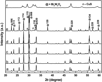 | ||
| Fig. 1 The XRD patterns of (a) BWO, (b) CuS5BWO, (c) CuS10BWO, (d) CuS15BWO, (e) CuS20BWO and (f) CuS. | ||
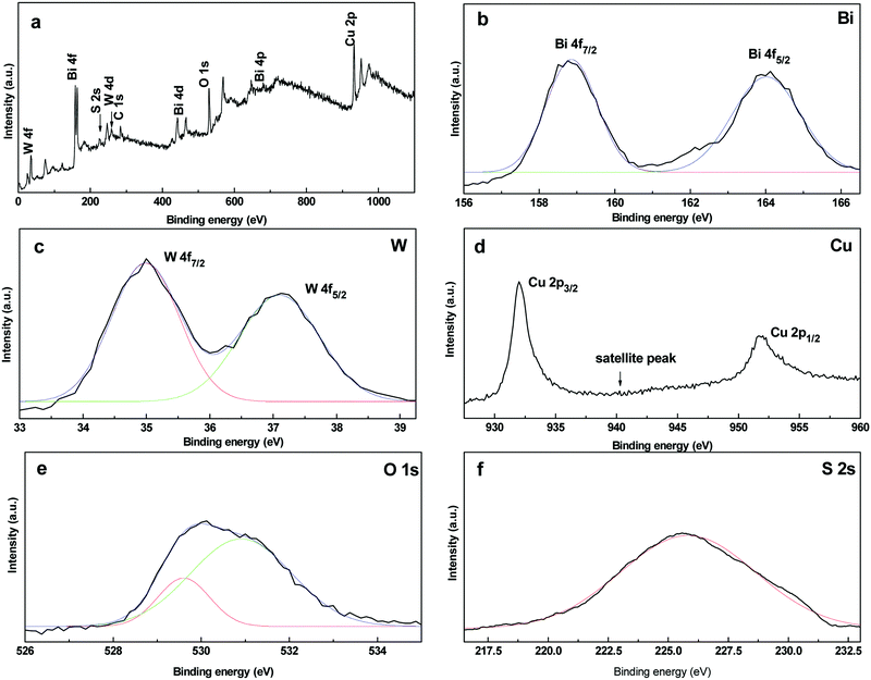
The XPS spectra of the CuS20BWO heterojunction material are presented in Fig. 2. The survey spectrum shows the presence of W, Bi, O, Cu and S along with adventitious carbon (Fig. 2a). In the high-resolution XPS spectra, a doublet is observed at 164.0 eV and 158.8 eV with a spin orbit splitting of 5.2 eV due to the Bi4f5/2 and Bi4f7/2 energy states of bismuth in the trivalent oxidation state (Fig. 2b). In the W4f region, a doublet is observed at 37.1 eV and 35.0 eV, which is assigned to the W4f5/2 and W4f7/2 states of the W6+ species (Fig. 2c). For the CuS20BWO material, the observed binding energy for the W+6 species is slightly lower than the literature reported values.34,35,38,42,52 This lowering in binding energy value can be ascribed to the change in the electronic environment of W due to the partial substitution of Cu2+ in the BWO lattice, which is in accordance with an earlier report.34 In the Cu2p region, a doublet is observed at 932.0 eV and 951.9 eV along with a small satellite peak at 941.9 eV. These spectral features are characteristics of the Cu2+ species in a sulphide environment (Fig. 2d).
The O1s high-resolution spectrum is broad and asymmetric due to the overlapping contributions from different oxide species. The O1s spectrum can be fitted into two peaks with the maxima at 529.6 and 530.9 eV corresponding to two different chemical environments. The peak at 529.6 eV can be assigned to (W2O7)2− perovskite layers while the peak at 530.9 eV is due to the interlayer oxygen of the (Bi2O2)2+ species (Fig. 2e).52 In the S2s region, a broad peak is apparent with a binding energy value of 225.7 eV due to the S2− ions of the CuS phase. The XPS analysis of CuS20BWO revealed the presence of CuS and Cu2+ substituted Bi2W2O9 phases in the heterojunction material.
The FTIR spectra (400–1000 cm−1) of the BWO and CuSBWO materials are presented in Fig. S2 (ESI†). The pure Bi2W2O9 material exhibits intense IR bands at 437, 561, 745, 851 and 952 cm−1. The bands at 437 and 561 cm−1 are assigned to Bi–O stretching whereas the peaks at 745, 851 and 952 cm−1 are due to the symmetric and asymmetric W–O stretching vibrations for the WO6 octahedron.40–46 All the essential vibrational features of BWO are retained in the heterojunction material. However, the W–O vibrational bands are shifted to lower wavenumber values by 6–8 cm−1. This observation suggests a change in the W–O bond strength upon Cu2+ substitution in the BWO lattice. The IR spectral study was found to be complimentary to the XRD and XPS studies, where the incorporation of Cu2+ ions into the BWO lattice was observed. In addition, all the CuSBWO heterojunction materials show a broad and weak IR band at 616 cm−1 corresponding to the Cu–S stretching vibration.34
The UV-vis-DRS spectra of the BWO and CuSBWO materials are presented in Fig. 3I. The pure BWO material shows an absorption edge near 450 nm (Fig. 3Ia). The absorption edge for CuS commences near 890 nm (Fig. 3If). The CuSBWO materials show enhanced visible light absorption in comparison to the pure BWO material (Fig. 3Ib–e). For all CuSBWO materials, a new absorption feature was noticed in the visible region between 400 and 850 nm. The intensity of this absorption feature increases gradually with an increase in CuS content. The optical band gap values of the Bi2W2O9, CuS and CuSBWO materials calculated from Tauc's plot (Fig. S3, ESI†) are presented in Table 1. Pure BWO and CuS exhibit a band gap of 3.0 eV and 1.5 eV, respectively, which are consistent with the reported values.31,37,47,48 The band gap values for the CuS and BWO phases in the CuSBWO materials are slightly higher than the parent bulk samples possibly due to the quantum confinement effect.
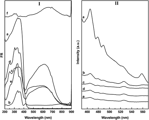 | ||
| Fig. 3 The UV-vis-DRS and PL spectra of (a) BWO, (b) CuS5BWO, (c) CuS10BWO, (d) CuS15BWO, (e) CuS20BWO and (f) CuS. | ||
| Sl. no. | Catalyst | Surface area (m2 g−1) | Band gap (eV) | Band position wrt NHE (eV) | ||||
|---|---|---|---|---|---|---|---|---|
| BWO | CuS | |||||||
| BWO | CuS | |||||||
| VB | CB | VB | CB | |||||
| 1 | BWO | 14.6 | 3.0 | — | +3.3 | +0.3 | — | — |
| 2 | CuS | 42.5 | 1.5 | — | — | — | +1.54 | +0.04 |
| 3 | CuS5BWO | 25.8 | 3.20 | — | +3.40 | +0.20 | — | — |
| 4 | CuS10BWO | 31.3 | 3.02 | 1.71 | +3.31 | +0.29 | +1.645 | −0.065 |
| 5 | CuS15BWO | 33.6 | 3.07 | 1.65 | +3.335 | +0.265 | +1.615 | −0.035 |
| 6 | CuS20BWO | 32.9 | 3.02 | 1.66 | +3.31 | +0.29 | +1.62 | −0.04 |
Fig. 3II shows the room temperature PL spectra of the BWO and CuSBWO heterojunction materials excited at 320 nm. The emission bands observed at 465 and 560 nm for BWO can be assigned to the band transition and the presence of defects and vacancies in this material (Fig. 3IIa).33,34,37 Upon modification with CuS, the intensity of the PL emission bands decreases significantly for all the CuSBWO heterojunction materials (Fig. 3IIb–e). The drastic decrease in PL intensities indicates efficient separation of excitons in the CuSBWO heterojunction materials. The UV-vis-DRS and PL studies along with the calculated band gap values of the CuSBWO heterojunction materials indicate that these materials can be used as photocatalysts under visible light.
The FESEM images of the BWO and CuSBWO materials are presented in Fig. 4. The BWO sample contains plate-like micron-sized particles of different dimensions (Fig. 4a). The planar dimensions of the plates are between 4 and 10 μm, whereas the thickness is between 0.8 and 1.5 μm. The smooth surfaces of the BWO plates indicate the uniform growth of the material in the XY direction. The red-encircled highlighted areas in Fig. 4a display the different growing stages of the BWO plates. The spherical dot encircled in blue colour represents the nucleation point for the growth of the BWO plates along the planar directions (Fig. 4a). Upon hydrothermal treatment of the BWO material in the presence of thiourea and the copper salt precursor, a drastic morphological rearrangement was noticed leading to the formation of hierarchical nanostructures. All the CuSBWO heterojunction materials contain submicron sized hierarchical spheres having a typical diameter between 0.6 and 0.8 μm. The spherical particles are formed by the hierarchical organization of the BWO nanosheets and the CuS nanorods (Fig. 4b–e).
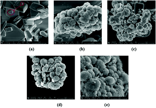 | ||
| Fig. 4 FESEM images of the (a) BWO, (b) CuS5BWO, (c) CuS10BWO, (d) CuS15BWO and (e) CuS20BWO heterojunction materials. | ||
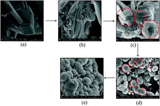
In order to further probe the different stages of formation of the spherical particles, the hydrothermally treated samples were analysed at different time intervals using FESEM (Fig. 5). Upon hydrothermal treatment, the BWO plates were initially desegregated to BWO nanosheets. The lateral view of a hydrothermally treated BWO plate in Fig. 5b indicates its layer-by-layer desegregation. The BWO nanosheets subsequently arranged themselves concentrically to form spherical structures. CuS nanorods are preferably deposited along the outer periphery and in the void spaces between the nanosheets to form the hierarchical spherical structure (Fig. 5c). Fig. 5d depicts the top view of a few partially formed hierarchical spheres. The concentric arrangement of the nanosheets can be inferred from Fig. 5d. The desegregated BWO nanosheets have a typical length and breadth between 150 and 300 nm and thickness between 25 and 30 nm (Fig. 5c). Similarly, the CuS nanorods have a typical length between 120 and 200 nm with the diameter ranging from 25 to 35 nm. The desegregation of the BWO plates to nanosheets also occurs in the presence of thiourea (Fig. S4a, ESI†). However, when the BWO sample is hydrothermally treated in the absence of thiourea, no perceivable change in morphology was noticed. The BWO plates remain intact even after 24 h of hydrothermal treatment at 150 °C (Fig. S4b, ESI†). This observation suggests that the thiourea is crucial for the desegregation of the plate structure to nanosheets. Thiourea is a chelating ligand with N and S as potential sites for coordination to metal ions. The interlayer Bi3+ ions can coordinate to the S atom of thiourea due to their chalcophile properties. The intercalation of thiourea under hydrothermal conditions into the BWO interlayer can lead to the formation of BWO nanosheets.
The morphological features, size and formation of the heterojunctions were further investigated for the CuS20BWO material using TEM analysis (Fig. 6). The presence of spherical particles with 0.6–0.8 μm diameter was confirmed from the TEM study (Fig. 6a and b). Fig. 6c depicts the TEM image of a partially formed sphere growing in the −X direction. The hierarchical organization of the BWO nanosheets and CuS nanorods can clearly be observed from this image (Fig. 6c). The HRTEM images of the CuS20BWO material are presented in Fig. 6d–f. In Fig. 6d, a single CuS nanorod with a length of 70 nm and a diameter of 30 nm can be visualized. The CuS nanorods are in microscopically intimate contact with the BWO nanosheets (Fig. 6e). The high-resolution image in Fig. 6f depicts the formation of heterojunctions between the BWO and CuS phases.53 Two different sets of lattice fringes running in different directions correspond to the (105) and (106) crystallographic planes of Bi2W2O9 and CuS, respectively (Fig. 6f). The EDS mapping and EDX spectrum of the CuS20BWO material are presented in Fig. 6g–i. The EDS mapping study reflects the presence of the CuS nanorods in the CuSBWO sample. The presence of Bi, W, O, Cu and S with required stoichiometry is confirmed from the EDX spectrum (Fig. 6i). The specific surface areas of the heterojunction materials are presented in Table 1. The CuSBWO material shows surface area values in the range of 25–33 m2 g−1.
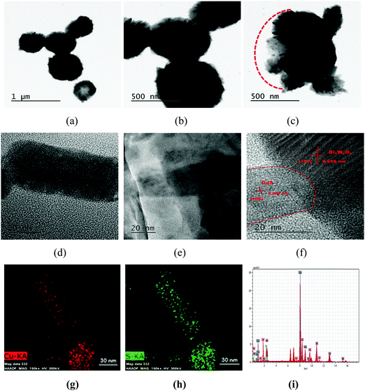 | ||
| Fig. 6 (a–f) TEM images, (g and h) EDS mapping and (i) EDX spectrum of the CuS20BWO heterojunction material. | ||
3.2. Photocatalytic degradation of diuron pesticide
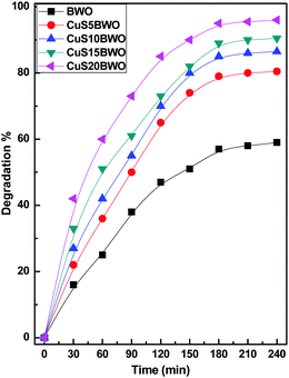 | ||
| Fig. 7 Photocatalytic efficiency of the CuSBWO catalysts for the degradation of diuron (10 ppm DU, 200 μl of 30% H2O2, and 75 mg of the catalyst). | ||
Fig. 8 shows the pseudo-first-order kinetic plots for the degradation of diuron up to 3 h of reaction time. The Kapp value increases linearly with CuS content in the heterojunction material. The Kapp value of the CuS20BWO heterojunction is nearly 4 times higher than that of pure BWO material and 2 times higher than that of the CuS5BWO heterojunction (Fig. 8II).
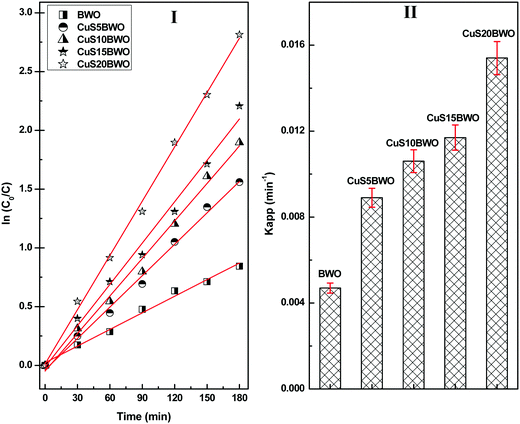 | ||
| Fig. 8 (I) Pseudo-first-order kinetic plots and (II) the apparent rate constants of the CuSBWO heterojunction photocatalysts for the degradation of diuron. | ||
Fig. 9 shows the effects of the various reaction parameters on the photocatalytic degradation of diuron using the CuS20BWO photocatalyst. The catalyst amount was varied ranging from 25 to 100 mg. The degradation rate increases with an increase in the catalyst amount up to 75 mg, beyond which a marginal decrease in the degradation efficiency was noticed (Fig. 9I). The decrease in the degradation rate at higher catalyst amount can be attributed to the scattering of incident light by the catalyst particles from the reaction mixture.
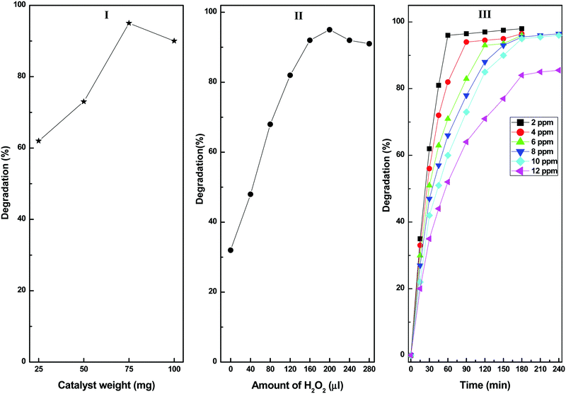 | ||
| Fig. 9 (I) Effect of catalyst dose, (II) H2O2 concentration and (III) diuron concentration on the photocatalytic degradation catalysed by the CuS20BWO photocatalyst. | ||
The effect of H2O2 concentration on diuron degradation is presented in Fig. 9II. The diuron degradation increases with an increase in the H2O2 concentration before attaining saturation at 200 μl. Beyond this value, there is a minor decrease in the degradation efficiency probably due to the trapping of OH˙ radicals by the excess H2O2 species resulting in the generation of HO2˙ radicals. The HO2˙ radical being a weaker oxidizing agent than the OH˙ radicals is responsible for the observed decrease in degradation efficiency.54 In order to study the effect of pH, the pH of the diuron solution was varied between 2 and 10 by using 0.1 M NaOH and HCl solutions. It was observed that at acidic pH, the diuron degradation rate is higher, and it decreases with increasing pH (figure not shown). The decrease in degradation rate in basic media can be ascribed to the reaction of the hydroxyl radicals with the OH− ions to generate O− species.10 Moreover, in basic media, H2O2 becomes unstable and easily dissociates into H2O and O2, which decreases the degradation rate.54 After optimizing various reaction parameters, we studied the catalytic efficiency of the CuS20BWO-catalysed degradation process by varying the diuron concentration between 2 and12 ppm. Up to 10 ppm diuron concentration, the degradation rate is very fast providing >90% degradation within 3 h of irradiation. However, for the 12 ppm sample, the reaction rate is relatively sluggish with 80% degradation achieved after 3 h of irradiation (Fig. 9III). This optimization study revealed that up to 100 ml of 10 ppm diuron solution can be degraded efficiently using 75 mg of CuS20BWO along with 200 μl of H2O2 as oxidant within 3 h of reaction time.
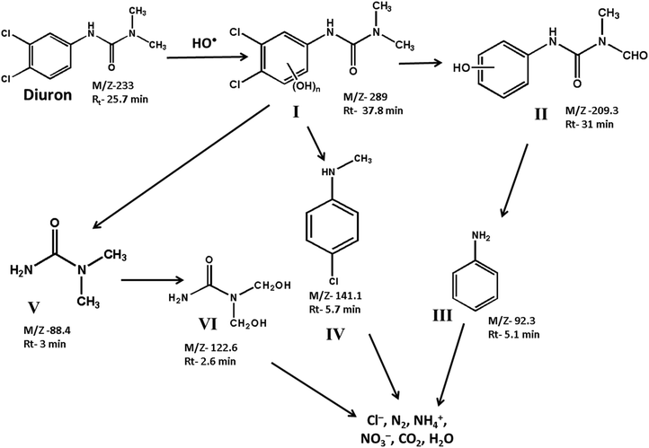
The degradation products formed at different stages of diuron degradation were analysed using GC/MS analysis (Fig. S7, ESI†). Six different products were identified based on the molecular ion peak and obtained mass fragments. Based on the GC/MS data, we proposed a plausible pathway for the photocatalytic degradation of diuron using H2O2 as oxidant (Scheme 1). In the first step, the hydroxyl radicals generated on the catalyst surface attack the diuron molecule to provide a high molecular weight hydroxylated product I. The product I is formed rapidly in the reaction mixture within 10 min of irradiation. Such a high molecular weight product has been observed earlier during the photocatalytic degradation of diuron over a TiO2 catalyst.11 The hydroxylated diuron species (I) undergo a rapid dehalogenation reaction resulting in the loss of Cl− ions. Simultaneously, the alkyl groups of diuron are oxidized to form the intermediate product II.19–22 The product I also decomposes to produce N, N-dimethyl urea (product V) and N-methyl chloroaniline (product IV). The product II undergoes further decomposition on the catalyst surface producing aniline (product III). The N,N-dimethyl urea (product V) is subsequently oxidized to bis(hydroxymethyl)urea (product VI). The intermediate products so formed are finally mineralized over the catalyst surface to give Cl−, NO3−, NH4+, CO2 and H2O as the final products.
Scavenger experiments were carried out to understand the role of different reactive species towards the degradation of diuron (Fig. S8, ESI†). The scavenger experiments were conducted by irradiating a reaction mixture containing an equimolar quantity of radical scavengers and the CuS20BWO catalyst (Fig. 11). In the presence of a hole (h+) scavenger (ammonium oxalate) and a hydroxyl radical (˙OH) scavenger (t-butyl alcohol), a drastic decrease in the degradation rate was observed. The scavenger experiment confirms that the photogenerated hydroxyl radicals and holes are the primary species responsible for the degradation of diuron (Fig. 11).
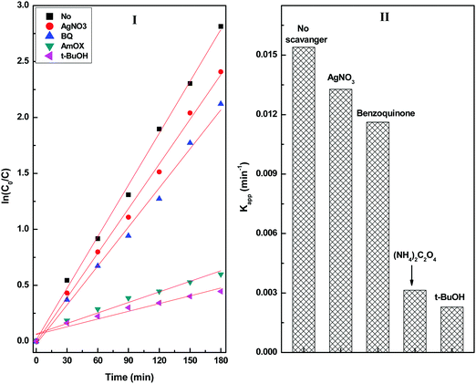 | ||
| Fig. 11 (I) Pseudo-first-order kinetic plots and (II) the apparent rate constant of the CuS20BWO heterojunction photocatalyst in the presence of different radical scavengers. | ||
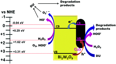
The calculated valence band (VB) and conduction band (CB) positions for the CuSBWO heterojunction materials are listed in Table 1 (detailed calculation is presented in the ESI†). The VB and CB positions for the CuS and BWO components are aligned in a favourable manner for the facile electron transfer from the CB of CuS to the CB of Bi2W2O9. Simultaneously, the holes can migrate in the opposite direction in the VB resulting in efficient charge carrier separation (Fig. 12). Such an arrangement of the band positions is characteristic of a type II heterojunction. A plausible mechanism for the degradation of diuron on the CuSBWO surface is proposed in Fig. 12. Upon irradiation with visible light, the electron population increases in the CB of the BWO component while the hole population increases in the VB of the CuS component. H2O2 and O2 are activated to the hydroxyl radical (HO˙) and the superoxide radical (O2˙−), respectively, in the CB of the BWO component. The hydroxyl radicals can also be generated by trapping of holes by the surface hydroxyl groups.21,22 Scavenger experiments confirmed the participation of these transient species in the photocatalytic degradation reaction. The preferred sites for the attack of the OH˙ radical are the methyl group and the aromatic ring leading to hydroxylated and subsequent oxidized products (Scheme 1).11,20–22 In the VB of CuS, H2O2 is oxidized to give hydroperoxide radicals (HOO˙). The hydroperoxide radicals upon reaction with diuron can generate a peroxide intermediate, which can disproportionate to give product II (Scheme 1).21 Moreover, the accumulated hole species in the VB of CuS, due to their oxidizing properties, can also contribute to the oxidative degradation of diuron. The intermediate oxidized products so formed undergo further mineralization on the catalyst surface. The stability and recyclability of the CuSBWO heterojunction photocatalyst was checked for five consecutive cycles. The CuS20BWO heterojunction photocatalyst exhibited stable activity up to five consecutive cycles (Fig. S9, ESI†). The XRD profiles of the CuS20BWO materials after successive catalytic cycles are presented in Fig. S10 (ESI†). No perceivable change in the XRD patterns was noticed, indicating the high phase stability of the material in the photocatalytic experiments. Overall, the photocatalytic method developed in this work is advantageous in terms of the use of visible light as energy source, the minimal use of oxidant and catalyst and shorter reaction times.
4. Conclusion
In this work, we have prepared novel type II CuS/Bi2W2O9 heterojunction materials and studied their photocatalytic activity for the visible light-assisted degradation of diuron pesticide. A phase pure Bi2W2O9 material is obtained by a facile combustion method using urea as the fuel. The XRD study confirmed the presence of orthorhombic Bi2W2O9 and hexagonal covellite CuS in the heterojunction material. The partial substitution of Cu2+ in the Bi2W2O9 lattice leads to the formation of a nonstoichiometric solid solution phase. The Bi2W2O9 material contains micron-sized plates with a planar dimension of 4–10 μm and a thickness of 0.8–1.5 μm. The Bi2W2O9 plates desegregate to nanosheets during the hydrothermal synthesis of the CuS/Bi2W2O9 heterojunction. The Bi2W2O9 nanosheets and the CuS nanorods are hierarchically organised to give a microspherical structure. The hierarchical organization promotes microscopic close contact between the Bi2W2O9 and CuS phases facilitating the easy movement of excitons. The optical absorption and photoluminescence study suggested a significant increase in visible light absorption and enhanced charge carrier separation properties. The CuS/Bi2W2O9 heterojunction exhibited excellent photocatalytic activity towards the visible light-assisted mineralization of diuron. A mechanistic study revealed that the degradation of diuron is a cascade process involving dechlorination, alkyl oxidation and oxidative ring opening leading to its complete mineralization. The CuS/Bi2W2O9 heterojunction photocatalyst developed in this work is stable and highly efficient for diuron degradation, making it a viable and economic alternative to the TiO2-based UV active photocatalyst.Conflicts of interest
There are no conflicts to declare.Acknowledgements
We thank DST-WTI, New Delhi, India for financial support through a Grant No. DST/TM/WTI/2K15/93.References
- K. Noguera-Oviedo and D. S. Aga, J. Hazard. Mater., 2016, 316, 242–251 CrossRef CAS PubMed.
- G. L. Puma, B. Toepfer and A. Gora, Catal. Today, 2007, 124, 124–132 CrossRef.
- R. Andreozzi, V. Caprio, A. Insola, R. Marotta and R. Sanchirico, Water Res., 2000, 34, 620–628 CrossRef CAS.
- J. Choi, H. Lee, Y. Choi, S. Kim, S. Lee, S. Lee, W. Choi and J. Lee, Appl. Catal., B, 2014, 147, 8–16 CrossRef CAS.
- K. Y. Foo and B. H. Hameed, J. Hazard. Mater., 2010, 175, 1–11 CrossRef CAS PubMed.
- M. S. Lucas, J. A. Peres and G. L. Puma, Sep. Purif. Technol., 2010, 72, 235–241 CrossRef CAS.
- M. E. Madani, C. Guillard, N. Perol, J. M. Chovelon, M. E. Azzouzi, A. Zrineh and J. M. Herrmann, Appl. Catal., B, 2006, 65, 70–76 CrossRef.
- P. Sharma, V. Bhalla, S. Tuteja, M. Kukkar and C. R. Suri, Analyst, 2012, 137, 2495–2502 RSC.
- S. Giacomazzi and N. Cochet, Chemosphere, 2004, 56, 1021–1032 CrossRef CAS PubMed.
- W. Khongthon, G. Jovanovic, A. Yokochi, P. Sangvanich and V. Pavarajarn, Chem. Eng. J., 2016, 292, 298–307 CrossRef CAS.
- H. Katsumata, M. Sada, Y. Nakaoka, S. Kaneco, T. Suzuki and K. Ohta, J. Hazard. Mater., 2009, 171, 1081–1087 CrossRef CAS PubMed.
- M. Quirantes, R. Nogales and E. Romero, J. Hazard. Mater., 2017, 331, 300–308 CrossRef CAS PubMed.
- J. Villaverde, M. R. Bellido, F. Merchan and E. Morillo, J. Environ. Manage., 2017, 188, 379–386 CrossRef CAS PubMed.
- M. Carrier, M. Besson, C. Guillard and E. Gonze, Appl. Catal., B, 2009, 91, 275–283 CrossRef CAS.
- E. C. Catalkaya and F. Kargi, Chemosphere, 2007, 69, 485–492 CrossRef CAS PubMed.
- P. Mazellier and B. Sulzberger, Environ. Sci. Technol., 2001, 35, 3314–3320 CrossRef CAS PubMed.
- B. R. Saranya, V. Sathiyanarayanan and S. T. Maheswari, RSC Adv., 2016, 6, 110970–110975 RSC.
- D. Bamba, P. Atheba, D. Robert, A. Trokourey and B. Dongui, Environ. Chem. Lett., 2008, 6, 163–167 CrossRef CAS.
- R. R. Solis, F. J. Rivas, A. M. Piernas and A. Aguera, Chem. Eng. J., 2016, 292, 72–81 CrossRef CAS.
- H. Krysova, J. Krysa, K. Macounova and J. Jirkovsky, J. Chem. Technol. Biotechnol., 1998, 72, 169–175 CrossRef CAS.
- M. Carrier, C. Guillard, M. Besson, C. Bordes and H. Chermette, J. Phys. Chem. A, 2009, 113, 6365–6374 CrossRef CAS PubMed.
- K. Macounova, H. Krysova, J. Ludvık and J. Jirkovsky, J. Photochem. Photobiol., A, 2003, 156, 273–282 CrossRef CAS.
- C. B. Somrani, F. Fajula, A. Finiels, P. Graffin, P. Geneste and J. L. Olive, New J. Chem., 2000, 24, 999–1002 RSC.
- H. Zhao, F. Tian, R. Wang and R. Chen, Rev. Adv. Sci. Eng., 2014, 3, 3–27 CrossRef.
- X. Lin, D. Xu, Y. Xi, R. Zhao, L. Zhao, M. Song, H. Zhai, G. Che and L. Chang, Colloids Surf., A, 2017, 513, 117–124 CrossRef CAS.
- X. Lin, Y. Wang, J. Zheng, C. Liu, Y. Yang and G. Che, Dalton Trans., 2015, 44, 19185–19193 RSC.
- X. Li, X. Guo, W. Shi, L. Zhao, Y. Yan and Q. Wang, J. Alloys Compd., 2015, 635, 256–264 CrossRef.
- X. Lin, D. Xu, J. Zheng, M. Song, G. Che, Y. Wang, Y. Yang, C. Liu, L. Zhao and L. Chang, J. Alloys Compd., 2016, 688, 891–898 CrossRef CAS.
- F. Guo, W. Shi, X. Lin, X. Yan, Y. Guo and G. Che, Sep. Purif. Technol., 2015, 141, 246–255 CrossRef CAS.
- N. Zhang, R. Ciriminna, M. Pagliaro and Y. J. Xu, Chem. Soc. Rev., 2014, 43, 5276–5287 RSC.
- A. Kudo and S. Hijji, Chem. Lett., 1999, 1103–1104 CrossRef CAS.
- J. C. C. Mesjard, B. Frit and A. Watanabe, J. Mater. Chem., 1999, 9, 1319–1322 RSC.
- Y. P. Bhoi, D. P. Rout and B. G. Mishra, J. Cluster Sci., 2016, 27, 267–284 CrossRef CAS.
- Y. P. Bhoi, S. R. Pradhan, C. Behera and B. G. Mishra, RSC Adv., 2016, 6, 35589–35601 RSC.
- S. O. Alfaro, A. M. Cruz, L. M. T. Martínez and S. W. Lee, Catal. Commun., 2010, 11, 326–330 CrossRef.
- S. O. Alfaro and A. M. Cruz, Appl. Catal., A, 2010, 383, 128–133 CrossRef CAS.
- J. Tang and J. Ye, J. Mater. Chem., 2005, 15, 4246–4251 RSC.
- A. M. Cruz, S. O. Alfaro, L. M. T. Martínez and I. J. Ramírez, J. Ceram. Proc. Res., 2008, 9, 490–494 Search PubMed.
- A. Feteira and D. C. Sinclair, J. Am. Ceram. Soc., 2008, 91, 1338–1341 CrossRef CAS.
- L. Wu, J. Xia, J. Wu and Q. Li, Ionics, 2015, 21, 3239–3244 CrossRef CAS.
- O. M. Bordun, A. T. Stetskiv and T. M. Yaremchuk, J. Appl. Spectrosc., 2004, 71, 136–138 CrossRef CAS.
- M. Maczka, M. Ptak, L. Kepinski, P. E. Tomaszewski and J. Hanuza, Vib. Spectrosc., 2010, 53, 199–203 CrossRef CAS.
- H. Wang, L. Zhang, Z. Chen, J. Hu, S. Li, Z. Wang, J. Liu and X. Wang, Chem. Soc. Rev., 2014, 43, 5234–5244 RSC.
- S. J. A. Moniz, S. A. Shevlin, D. J. Martin, Z. X. Guo and J. Tang, Energy Environ. Sci., 2015, 8, 731–759 CAS.
- Y. Wang, Q. Wang, X. Zhan, F. Wang, M. Safdar and J. He, Nanoscale, 2013, 5, 8326–8339 RSC.
- R. Marschall, Adv. Funct. Mater., 2014, 24, 2421–2440 CrossRef CAS.
- J. Kundu and D. Pradhan, ACS Appl. Mater. Interfaces, 2014, 6, 1823–1834 CAS.
- K. Manjunath, V. S. Souza, G. Nagaraju, J. M. L. Santos, J. Dupont and T. Ramakrishnappa, New J. Chem., 2016, 40, 10172–10180 RSC.
- X. Meng, G. Tian, Y. Chen, R. Zhai, J. Zhou, Y. Shi, X. Cao, W. Zhoua and H. Fu, CrystEngComm, 2013, 15, 5144–5149 RSC.
- Y. Shi, Y. Chen, G. Tian, L. Wang, Y. Xiao and H. Fu, ChemCatChem, 2015, 7, 1684–1690 CrossRef CAS.
- S. R. Jain and K. C. Adiga, Combust. Flame, 1981, 40, 71–79 CrossRef CAS.
- D. Wang, Y. Zhen, G. Xue, F. Fu, X. Liua and D. Li, J. Mater. Chem. C, 2013, 1, 4153–4162 RSC.
- Y. P. Bhoi and B. G. Mishra, Chem. Eng. J., 2017, 316, 70–81 CrossRef CAS.
- C. C. Wong and W. Chu, Environ. Sci. Technol., 2003, 37, 2310–2316 CrossRef CAS PubMed.
Footnote |
| † Electronic supplementary information (ESI) available: Tauc's plots, FESEM of hydrothermally treated Bi2W2O9 in the presence and absence of thiourea, GC-MS plots, kinetic plots and the reusability study of CuS/Bi2W2O9 heterojunction materials. See DOI: 10.1039/c7nj03390g |
| This journal is © The Royal Society of Chemistry and the Centre National de la Recherche Scientifique 2018 |

