A simple, rapid and efficient flame synthesis of ultrafine LiNi0.95−xCoxTi0.05O2 (x = 0.25 and 0.30): a versatile route to synthesize Ni-rich cathode materials for Li-ion batteries†
Laxman
Singh
,
Jiwon
Lee
,
Geun Wan
Kim
,
Minsoo
Ji
,
Chaewon
Moon
,
Hansol
Lee
,
Ji Won
Ha
 and
Youngil
Lee
 *
*
Department of Chemistry, University of Ulsan, 93 Deahak-ro, Nam-Gu, Ulsan 44610, Republic of Korea. E-mail: nmryil@ulsan.ac.kr; Fax: +82-52-259-2348; Tel: +82-52-259-2341
First published on 20th November 2017
Abstract
A simple, rapid, and efficient flame synthesis method was developed to fabricate LiNi0.95−xCoxTi0.05O2 (x = 0.25 and 0.30) cathode materials for Li-ion batteries. The ignition of metal nitrate precursors with a reddish flame was completed within 15–20 s. The complete procedure to obtain the LiNi0.95−xCoxTi0.05O2 precursor powder took 30–55 min, which is the simplest as well as the most rapid and efficient method among the synthesis methods reported thus far to obtain an analogous Ni-rich, LiNi0.70Co0.30O2 cathode material. X-ray diffraction confirmed the formation of a single phase of LiNi0.95−xCoxTi0.05O2 (x = 0.25 and 0.30) calcined at 800 °C for 12 h. Scanning electron microscopy (SEM) and transmission electron microscopy revealed the ultrafine nature of the particles. SEM showed grains with smooth surfaces and size in the range of 200 nm–0.4 μm, and TEM displayed the particles with a size range of 90 nm–0.2 μm. The fabricated materials showed discharge specific capacities of 159 mA h g−1 and 137 mA h g−1 at a 0.1C rate for the initial cycle at room temperature for LiNi0.95−xCoxTi0.05O2 with x = 0.25 and 0.30, respectively. These results suggest that LiNi0.95−xCoxTi0.05O2 synthesized via this facile route shows promising electrochemical activity. Consequently, the flame synthesis technique can be very attractive for the facile fabrication of structurally similar lithiated nickel–cobalt oxides for use as a cathode material for Li-ion batteries that are suitable for mass production.
1. Introduction
Ni-rich, Li1−xNi1−yMyO2 (Co, Mn, Al etc.), systems are the most promising candidates for cathode materials with strong potential for commercial applications in advanced lithium-ion batteries for electric vehicles (EVs) and hybrid electric vehicles (HEVs).1 In particular, the LiNi1−xCoxO2 system has advantages over the pure isostructural layered oxide end member of LiCoO2 and LiNiO2 in terms of its structural and thermal stability, enhanced electrochemical properties with higher capacity, and better cyclability. Of compounds in the LiNi1−xCoxO2 system, LiNi0.7Co0.3O2 exhibits excellent capacity and good reversibility, but this solid solution shows poor intrinsic electronic conductivity, which contributes to diminished electrochemical performance during cycling. The electrochemical performance of cathode materials is strongly dependent on the fabrication process of the materials. Traditional solid-state techniques are generally used to fabricate lithiated nickel–cobalt oxides with the starting materials, Li2CO3 or LiOH·H2O, NiO or NiCO3, and Co3O4 or CoCO3, with a stoichiometric amount calcined for a long duration with several intermediate grinding steps.2,3 On the other hand, wet chemical synthesis provides a better option for the fabrication of lithiated transition-metal oxides because ultrafine powders with a small particle size of complex compositions with high purity and homogeneity can be prepared easily compared to solid-state techniques. In addition, ultrafine powders with small particle sizes and the reduction of Li/Ni disorder are considered an advantage for improving the electrochemical performance of LiNi1−yCoyO2 systems.4 Various routes for the synthesis of lithiated nickel–cobalt oxides have been reported, such as the sol–gel method,5–8 the co-precipitation method,9,10 and the combustion method.11–14 Among them, the combustion method for the synthesis of nanosized or ultrafine oxide materials has attracted considerable interest.15 The combustion method involves the use of metal nitrate together with the corresponding complexing agent, such as urea, hydrazine, citric, acetic acid, glycine, tartaric, or glycerol in aqueous medium, which results in complexation of the metal by poly-carboxylic acid to produce optimized combustion synthesis and requires a precalcination step for the intermediate decomposition and removal of excess organic precursors.16,17 This article provides an effective method to fabricate LiNi0.95−xCoxTi0.05O2 (x = 0.25 and 0.30) materials with their spectroscopic characterization. In this proposed method, there is no need to add the complexing agents as a fuel for metal nitrate precursors of Li, Ni, and Co. Metal nitrates are soluble in 2-methoxyethanol, which allows the auto ignition of metal nitrates with a reddish flame to form the desired precursor powder within 15–20 s; a single phase of the material is obtained in a single calcination step. The whole process to obtain the LiNi0.95−xCoxTi0.05O2 precursor powder was completed within 30–55 minutes. The present method is the simplest synthesis technique to obtain the LiNi0.95−xCoxTi0.05O2 powder as well as the Ni-rich isostructural compounds of LiNi1−yCoyO2 in comparison to other synthetic methods (see the ESI,† S1). In addition to the processing window, a new concept was also used to substitute a dopant at different sites for the same material, which allowed better substitution to enhance the electrochemical performance of the LiNi0.7Co0.3O2 cathode material. Herein, Ti4+ ions were substituted at the Ni-site and the Co-site in LiNi0.7Co0.3O2, and are abbreviated as LNTCO and LNCTO, respectively. Surprisingly, LNCTO exhibits better electrochemical performance by substitution of Ti4+ ions at the Co-site compared to that at the Ni-site. A comparison of the substitution of Ni and Co sites was made to examine the relationship between the substitution site and the electrochemical performance.2. Methods
2.1 Material synthesis
LiNO3 (98.0%, Junsei), Ni(NO3)2·6H2O (98.50%, Aldrich), Co(NO3)2·6H2O (98.0%, Junsei), TiO2 (99.9%, Sigma Aldrich), and 2-methoxyethanol (99.0%, Alfa Aesar) were used to prepare LiNi0.95−xCoxTi0.05O2 (x = 0.25 and 0.30) precursor powders. First, an appropriate amount of LiNO3, Ni(NO3)2·6H2O, and Co(NO3)2·6H2O were dissolved in a minimal amount of 2-methoxyethanol. Second, stoichiometric amounts of solid TiO2 were added to the solution. The resulting heterogeneous mixture was sonicated for 10–15 min and heated on a hot plate using a magnetic stirrer at 100–120 °C to evaporate the organic solvent, until self-ignition took place, which exhausted a large amount of gases with a reddish flame and produced a fluffy mass of the LiNi0.95−xCoxTi0.05O2 precursor powder. This synthetic technique involves the mixing of metal nitrate in a non-aqueous solvent of 2-methoxyethanol at the ionic level except TiO2. The organic solvent of 2-methoxyethanol acts as a fuel to induce a highly exothermal flame which can instantly provide ultrahigh thermal energy for the precursors of metal nitrates. They are decomposed in this environment to produce the desirable product. Finally, the resulting powder was calcined at 800 °C for 12 h in an O2 atmosphere in a tubular electrical furnace. Fig. 1 presents a schematic diagram of the flame synthesis technique to obtain LiNi0.95−xCoxTi0.05O2 (x = 0.25 and 0.30). A video of the flame synthesis technique taken during the flame reaction is available in the ESI,† S2.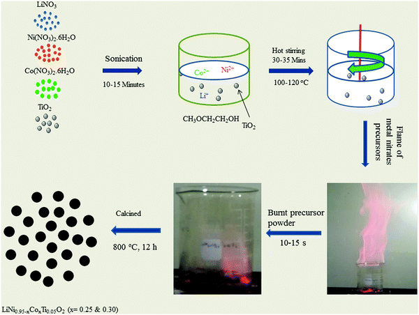 | ||
| Fig. 1 Schematic diagram of the flame synthetic technique to prepare LiNi0.95−xCoxTi0.05O2 (x = 0.25 and 0.30). | ||
2.2 Structural characterization
X-ray diffraction (XRD, Rigaku Ultima IV, Japan) with Cu Kα radiation was used to identify the phases of the synthesized material. Raman spectra (Ando Tech Sr-3031-A Raman spectrophotometer, Japan) were obtained for the qualitative structural analysis of the sample powder. The powders were analyzed in the range 400 up to 600 cm−1 using the Rayleigh wavelength (λ = 784.5 nm) with a laser power of 16.5 mW as the excitation source with an integration time of 180 s.7Li magic angle spinning (MAS) nuclear magnetic resonance (NMR) spectra werecollected on a Bruker Avance III 300 with a 7.04 T magnet at room temperature. For the MAS NMR experiments, a 2.5 mm MAS probe was used with a zirconia rotor at 116.64 MHz as the resonance frequency of 7Li. The 7Li NMR spectra were referenced to the external 1 M LiCl. A single pulse for 7Li was used to produce the NMR signal. The sample spinning rate was 25 kHz. The 7Li spectra were acquired with a 90° pulse length of 1.4 μs, a repetition delay of 0.5 s, 256 transients, and a spectral width of 0.23 MHz. The isotropic chemical shifts were identified by varying the spinning rates.
X-ray photoelectron spectroscopy (XPS, K-Alpha, Thermo Scientific, USA) of the materials was performed in wide scan survey mode and high-energy resolution using Al Kα radiation (1486.6 eV). The morphology of the prepared materials was observed by field emission scanning electron microscopy (SEM, Jeol JSM6500F, Japan). The particle size and elemental mapping of the sample were analyzed using a transmission electron microscope (TEM, JEM-2100F) with an Oxford energy dispersive X-ray (EDX) analyzer attached to it. For TEM measurements, samples were dispersed in an alcohol and then the drops of dispersed samples were placed on the carbon-coated copper grid.
2.3 Electrochemical tests
The electrodes used to measure the electrochemical performance were prepared by slurry casting and pressing a mixture of 80 wt% of the synthesized cathode material, 10 wt% of carbon black (Super P), 10 wt% of polyvinylidene fluoride (PVDF, Aldrich), and 3 mL of N-methylpyrrolidone (NMP) on aluminum foil followed by drying in a vacuum oven at 110 °C for 2 h. Lithium metal foil, 15 mm in diameter and 0.30 mm in thickness, was used as the counter electrode. The circular disk electrodes with Cellguard 2400 separators were assembled into 2016 coin cells in an argon-filled glove box. Non-aqueous 1.15 M LiPF6 in ethylene carbonate/dimethyl carbonate/diethyl carbonate with a 3![[thin space (1/6-em)]](https://www.rsc.org/images/entities/char_2009.gif) :
:![[thin space (1/6-em)]](https://www.rsc.org/images/entities/char_2009.gif) 4
4![[thin space (1/6-em)]](https://www.rsc.org/images/entities/char_2009.gif) :
:![[thin space (1/6-em)]](https://www.rsc.org/images/entities/char_2009.gif) 3 volume ratio was used as the electrolyte. The electrochemical cycle tests and cyclic voltammetry were performed at ambient temperature using a galvanostatic automatic battery cycler (WonATech WBCS3000, Korea). The cells for the rate test were cycled between 2.5 V and 4.5 V vs. Li/Li+ with a constant current–constant voltage (CC–CV) protocol in charging mode. Constant current rates at 0.1, 0.2, 0.5, 1.0, 2.0, and 3.0C were used. Cyclic voltammetry (CV) at room temperature for all samples was performed at a scan rate of 0.1 mV s−1 over the voltage range, 2.5–4.5 V, for 5 h.
3 volume ratio was used as the electrolyte. The electrochemical cycle tests and cyclic voltammetry were performed at ambient temperature using a galvanostatic automatic battery cycler (WonATech WBCS3000, Korea). The cells for the rate test were cycled between 2.5 V and 4.5 V vs. Li/Li+ with a constant current–constant voltage (CC–CV) protocol in charging mode. Constant current rates at 0.1, 0.2, 0.5, 1.0, 2.0, and 3.0C were used. Cyclic voltammetry (CV) at room temperature for all samples was performed at a scan rate of 0.1 mV s−1 over the voltage range, 2.5–4.5 V, for 5 h.
3. Results and discussion
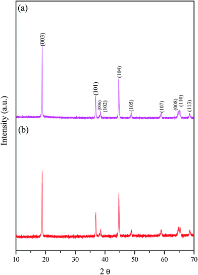
Fig. 2 shows the XRD patterns of the prepared LiNi0.95−xCoxTi0.05O2 (x = 0.25 and 0.30), which are abbreviated as LNCTO and LNTCO, respectively. XRD revealed a highly crystalline and single phase with a hexagonal structure without a secondary phase. The XRD patterns clearly show the splitting of (006)/(102) and (108)/(110) as doublets, which exhibit a highly ordered layered structure with a homogeneous distribution of elements. The lattice parameters of LiNi0.95−xCoxTi0.05O2 (x = 0.25 and 0.30) were calculated using ‘cell software’ and the values are listed in Table 1. The results show that Ti substitution does not change the layered structure. However, it causes a minute increase in the unit cell volume of LiNi0.70Co0.25Ti0.05O2 than LiNi0.70Co0.25Ti0.05O2 due to the large ionic radii difference of the substituent in the same coordination number of 6. The intensity ratios of the XRD peaks, I(003)/I(104), are considered an indicator of the ordering of lithium and other transition metal cations (Ni and Co). The I(003)/I(104) of LNCTO was 1.57 larger than that of LNTCO (1.32), which indicates that the substitution of Ti4+ ions at the Co-site would suppress the occupancy of Li+ layers by Ni2+ and increase the conductivity, leading to better electrochemical performance compared to that of LNTCO, as discussed later.18| Sample | Lattice parameter (a) (Å) | Lattice parameter (c) (Å) | Lattice volume (Å3) | Intensity ratio (003)/(104) |
|---|---|---|---|---|
| LNCTO | 2.778 | 14.543 | 97.256 | 1.57 |
| LNTCO | 2.775 | 14.569 | 97.203 | 1.32 |
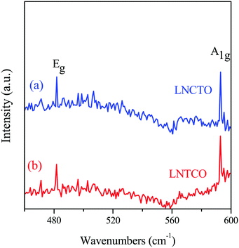
The phase and qualitative structural analyses of the LNCTO and LNTCO cathode materials were analyzed by Raman spectroscopy, as shown in Fig. 3. The spectra revealed Raman-active vibrational modes (A1g and Eg), which are generally observed in a rock salt-layered structure with R![[3 with combining macron]](https://www.rsc.org/images/entities/char_0033_0304.gif) m group symmetry.19 Two well-defined bands were observed at 481 and 592 cm−1, which are ascribed to the Eg (O–Co–O bending) and A1g (Co–O stretching) modes,20 respectively. This spectral result confirmed the formation of a rock salt-type structure, which is in good agreement with the previous studies of LiNi0.7Co0.3O2.21,22
m group symmetry.19 Two well-defined bands were observed at 481 and 592 cm−1, which are ascribed to the Eg (O–Co–O bending) and A1g (Co–O stretching) modes,20 respectively. This spectral result confirmed the formation of a rock salt-type structure, which is in good agreement with the previous studies of LiNi0.7Co0.3O2.21,22
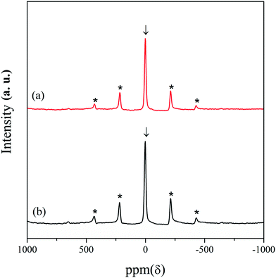
7Li magic angle spinning (MAS) nuclear magnetic resonance (NMR) experiments were carried out for further structural analysis of the LNCTO and LNTCO cathode materials, as shown in Fig. 4. A single isotropic resonance peak was observed at 0 ppm with broad spinning sideband manifolds marked as asterisks. The characteristic single peak at 0 ppm was observed, which is shown as a typical diamagnetic environment for Li atoms.23 Therefore, the appearance of a single isotropic peak at 0 ppm in both cathode materials confirmed the presence of a single type of Li site that was well matched with the reported literature.24,25
Fig. 5 shows the fitted results of XPS spectra for the synthesized LNCTO to provide information on the valence states of the elements. The spectrum of LNCTO revealed the presence of Li, Ni, Co, Ti, and O, respectively, which confirms the purity of the prepared material via flame synthesis. Fig. 5(a) shows the Li 1s peak located at 54.7 eV, which can be attributed to the presence of Li+ species in LNCTO.26 The Ni 2p spectrum in Fig. 5(b) shows two well-defined peaks with binding energies of 855.1 and 872.8 eV, which were assigned to 2p3/2 and 2p1/2, respectively. This is consistent with the energy characteristics of the Ni valence state for Ni2+ in NiO27 and Ni3+ in LiNiO2,28 respectively. Therefore, LNCTO revealed the existence of both Ni3+ and Ni2+ ions.
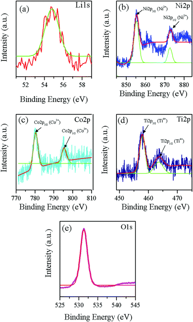 | ||
| Fig. 5 XPS spectra of flame synthesized LNCTO for (a) Li 1s, (b) Ni 2p, (c) Co 2p, (d) Ti 2p, and (e) O 1s. | ||
In contrast, the Co 2p spectrum in Fig. 5(c) was also characterized by two peaks at 779.9 and 794.9 eV for 2p3/2 and 2p1/2, respectively. Co ions in an oxygen environment represent the +3 oxidation state if the main peak positions are located around 780 and 795 eV.29,30 The Ti 2p spectrum in Fig. 5(d) exhibited double peaks of Ti 2p3/2 and Ti 2p1/2 located at 457.7 eV and 463.8 eV, respectively, which are characteristic of the +4 oxidation state for Ti4+.31,32 The O 1s spectrum in Fig. 5(e) exhibits a sharp peak centered at 531.3 eV, which suggests oxygen linked to metal ions as Li–O along with the Ni/Co–O for the layered structure cathode materials.33 The observed binding energy suggests that the valence states of Ni, Co, and Ti are mainly +2/+3, +3, and +4, respectively, which are consistent with previous results.26–32
Fig. 6(a) and (b) show SEM images of the LNCTO and LNTCO powders. The SEM images show the similar nature of morphology for both samples with the slight agglomeration of grains in LNTCO. SEM also revealed grains with smooth surfaces and particle sizes in the range of 200 nm–0.4 μm. The microstructure and surface morphology of the LNCTO and LNTCO materials were further characterized by TEM, as shown in Fig. 6(c) and (d). TEM revealed the ultrafine nature of the particles with a size range of 90 nm–0.2 μm, which is consistent with the SEM observations.
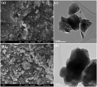 | ||
| Fig. 6 FE-SEM images of flame synthesized (a) LNTCO and (b) LNCTO, and HR-TEM images of (c) LNTCO and (d) LNCTO. | ||
Fig. 7 shows the EDX mapping images of LNCTO to determine the distribution of each element presented in the flame synthesized cathode materials. The EDX images of the LNCTO cathode showed a uniform distribution of the Ni, Co, Ti and O elements, as shown in Fig. 7. The EDX mapping image of Ti in Fig. 7(c) clearly showed a similar intensity and distribution to Ni, Co, and O, which indicates that all the elements are homogeneously mixed in the material. Although the percentage of Ti substitution in sample preparation was very low, the Ti in the sample was distributed uniformly, which highlights the merits of the suggested flame synthetic method. The purpose of this work was to develop a simple, rapid, and efficient chemistry-based synthetic method to prepare analogous materials of LiNi0.70Co0.30O2. To simplify the procedure, inexpensive solid TiO2 powder was also used as the titanium source to substitute Ti4+ in LiNi0.70Co0.30O2 instead of the very expensive alkoxide, oxynitrate, or chloride of titanium, which are difficult to handle and are extremely sensitive to the environmental conditions, such as moisture, light, and heat.
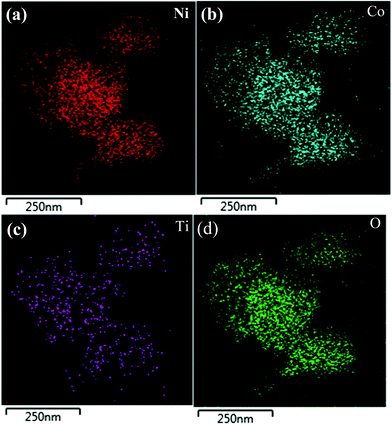 | ||
| Fig. 7 EDX elemental mapping images of flame synthesized LNCTO for elements (a) Ni, (b) Co, (c) Ti, and (d) O. | ||
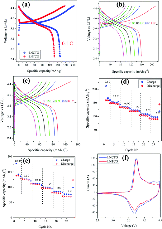
Fig. 8 displayed the electrochemical performance of LNCTO and LNTCO at various current rates of 0.1, 0.2, 0.5, 1, 2, and 3C in the potential range between 2.5 and 4.5 V vs. Li/Li+ at room temperature.
As shown in Fig. 8(a), LNCTO delivers an initial discharge capacity of 159 mA h g−1 at 0.1C rate, while LNTCO delivers 137 mA h g−1. Both the cathode materials showed an irreversible capacity loss between the initial charge/discharge. The initial charge/discharge capacity loss has also been reported earlier34 in the cathode materials containing Ni3+ which may arise due to the formation of electrochemically inactive regions in the cathode attributed to the oxidation of pre-existing Ni2+ ions occupying the Li layer in layered oxide materials.35–37 In addition, it can be seen that the reversible capacity loss for both LNCTO and LNTCO as shown in Fig. 8(b) and (c) is decreased with increasing polarization between charge and discharge profiles upon increasing the C rate from 0.1 to 3C. The charge/discharge results showed that LNCTO exhibits much better electrochemical performance than LNTCO for all C rates.
Fig. 8(d) and (e) compare the rate capabilities of both LNCTO and LNTCO cathode materials. For the first cycle, charge/discharge capacities for LNCTO at current rates of 0.2, 0.5, 1, 2, and 3C in Fig. 8(d) are 152.5/149.1, 135.3/133.2, 122.5/119.4, 110.5/104.3, and 99.7/91.7 mA h g−1, respectively, while those of LNTCO in Fig. 8(e) are 128.9/124.6, 112.1/110.4, 100.0/96.9, 86.7/81.4, and 77.5/70.1 mA h g−1, respectively. As shown in Fig. 8(d) and (e), the specific capacities of LNCTO for all of C rates are delivered larger than those of LNTCO. In addition, the coulombic efficiency of the LNCTO of the initial cycle at a 1C rate is 97.4%, which is also larger than that of LNTCO of 96.9%. It is clear that LNCTO at all C rates demonstrates a much better rate capability and higher reversible capacity than those of LNTCO. Even for the high rate of 3C, LNCTO delivered an excellent discharge capacity of 91.7 mA h g−1, which is much larger than that of LNTCO of 70.1 mA h g−1. The high reversible capacity and coulombic efficiency of LNCTO as compared to those of LNTCO can be attributed to its higher ordered structure and reducing magnitude of Li/Ni disorder which reduced Ni content in the lithium layer as mentioned above in the XRD results.38 In addition, the cycling performances of the flame synthesized LNCTO and LNTCO at the 1C rate for 50 cycles are shown in Fig. S3 (see the ESI,† S3). The initial discharge capacities of LNCTO and LNTCO are 119.3 and 103.1 mA h g−1, and their discharge capacities 50 cycles remain 87.0 and 69.7 mA h g−1, respectively. These correspond to the capacity retentions of 72.9 and 67.6% for LNCTO and LNTCO. It is shown that LNCTO has better reversibility than LNTCO. The electrochemical performance of flame synthesized LNCTO has also been compared with the previous analogous compound of LiNi.07Co0.3O2 based on different synthetic routes as listed in Table 2.39–43 It can be proved that the obtained specific discharge capacity of the flame synthesized LNCTO is comparable to those reported in the earlier literature.
| System | Synthetic route | Current density/rate | Initial discharge capacity (mA h g−1) | Ref. |
|---|---|---|---|---|
| LiNi0.65Co0.25Mn0.1O2 | Combustion synthesis | 0.05 C | 140 | 39 |
| LiNi0.65Mg0.05Co0.3O2 | Sol–gel synthesis | 0.1 C | 178.9 | 40 |
| LiNi0.70Co0.30O2 | Solid-state route | 200 μA cm−2 | 127 | 41 |
| LiNi0.7Co0.2Ti0.05Mg0.05O2 | Solid-state route | 0.1 C | 149 | 42 |
| LiNi0.70Co0.30O2 | Precipitation route | 15 mA g−1 | 126 | 43 |
| LiNi0.65Ti0.05Co0.30O2 | Flame synthesis | 0.1 C | 159 | This work |
Fig. 8(f) shows the cyclic voltammetry (CV) curves of LNCTO and LNTCO in the potential range of 2.5–4.5 V vs. Li/Li+ at a scan rate of 0.1 mV s−1. The CV curves for both LNCTO and LNTCO were characterized by two redox peaks. Highly symmetric peak profiles were observed for both materials, which indicate the good reversibility of Li+ in the extraction/insertion reactions. The anodic peaks were observed at 3.73 and 3.75 V for LNCTO and LNTCO, respectively, corresponding to the oxidation of Ni3+ to Ni4+, whereas the cathodic peaks at 3.68 and 3.69 V, corresponded to the reduction of Ni4+ to Ni3+ for LNCTO and LNTCO, respectively.44,45 Furthermore, the potential difference between the oxidation and reduction peaks was smaller for LNCTO (0.05 V) than for LNTCO (0.06 V), which indicates that electrode polarization can be reduced and electrons participate actively in the redox reactions for LNCTO by the substitution of Ti4+ ions at the Co-site compared to the Ni-site. Therefore, the substitution of the dopant at different sites in the same material can influence the electrochemical performance of the cathode material.
4. Conclusion
A simple, rapid, and efficient flame synthetic method to prepare cathode materials for Li-ion batteries with highly ordered layered structures was developed. A new strategy was also used to determine the influence of the dopant at different sites in the same material on the electrochemical performance. Using the new flame synthetic route, ultrafine LiNi0.95−xCoxTi0.05O2 (x = 0.25 and 0.30) cathode materials that deviated from normal stoichiometry were synthesized by a single calcination step. These materials are generally difficult to synthesize due to the additional nickel ions on the lithium sites. The flame synthesized materials were characterized using a range of spectroscopic techniques, which revealed a single phase with a well-ordered hexagonal layered structure. The substitution of Ti4+ ions at the Co-site in LiNi0.95−xCoxO2 showed better electrochemical performance than that at the Ni-site. Consequently, the developed flame synthetic technique is quite attractive for the facile fabrication of various lithium metal oxides, such as LiNi0.8Co0.2O2, LiNi0.76Co0.24O2, and LiNi0.8Co0.15Al0.05O2, (see the ESI,† S1) in the mass production of cathode materials for Li-ion batteries.Conflicts of interest
There are no conflicts to declare.Acknowledgements
This study was supported by the National Research Foundation (NRF-2015R1D1A3A01019167 for Y. Lee and NRF-2015R1D1A4A01019630 for L. Singh) and Priority Research Centers Program (NRF-2009-0093818) funded by the Ministry of Education of the Korean Government.References
- W. Liu, P. Oh, X. Liu, M. J. Lee, W. Cho, S. Chae, Y. Kim and J. Cho, Angew. Chem., Int. Ed., 2015, 54, 4440–4457 CrossRef CAS PubMed.
- M. Y. Song, H. Rim and E. Bang, J. Appl. Electrochem., 2004, 34, 383–389 CrossRef CAS.
- J. Y. Liao, S. M. Oh and A. Manthiram, ACS Appl. Mater. Interfaces, 2016, 8, 24543–24549 CAS.
- E. Lee, J. Blauwkamp, F. C. Castro, J. Wu, V. P. Dravid, P. Yan, C. Wang, S. Kim, C. Wolverton, R. Benedek, F. Dogan, J. S. Park, J. R. Croy and M. M. Thackeray, ACS Appl. Mater. Interfaces, 2016, 8, 27720–27729 CAS.
- Z. Tang, J. Bao, Q. Du, Y. Shao, M. Gao, B. Zou and C. Chen, ACS Appl. Mater. Interfaces, 2016, 8, 34879–34887 CAS.
- J. Cho and B. Park, J. Power Sources, 2001, 92, 35–39 CrossRef CAS.
- J. Cho, Chem. Mater., 2000, 12, 3089–3094 CrossRef CAS.
- C. J. Han, J. H. Yoon, W. I. Cho and H. Jang, J. Power Sources, 2004, 136, 132–138 CrossRef CAS.
- J. Su, Y. Su and M. Guo, J. New Mater. Electrochem. Syst., 2007, 10, 91–94 CAS.
- V. Augustyn, S. Therese, T. C. Turner and A. Manthiram, J. Mater. Chem. A, 2015, 3, 16604–16612 CAS.
- M. Song, I. Kwon and H. Kim, J. Appl. Electrochem., 2005, 35, 1073–1080 CrossRef CAS.
- P. Kalyani, N. Kalaiselvi, N. G. Renganathan and M. Raghavan, Mater. Res. Bull., 2004, 39, 41–54 CrossRef CAS.
- M. Dahbi, I. Saadounea and J. M. Amarilla, Electrochim. Acta, 2008, 53, 5266–5271 CrossRef CAS.
- P. Periasamy, H. S. Kim, S. H. Na, S. I. Moon and J. C. Lee, J. Power Sources, 2004, 132, 213–218 CrossRef CAS.
- A. Sutka and G. Mezinskis, Front. Mater. Sci., 2012, 6, 128–141 CrossRef.
- A. Varma, A. S. Mukasyan, A. S. Rogachev and K. V. Manukyan, Chem. Rev., 2016, 116, 14493–14586 CrossRef CAS PubMed.
- L. Singh, U. S. Rai, K. D. Mandal and N. B. Singh, Prog. Cryst. Growth Charact. Mater., 2014, 60, 15–62 CrossRef CAS.
- R. Santhanam, P. Jones, A. Sumana and B. Rambabu, J. Power Sources, 2010, 195, 7391–7396 CrossRef CAS.
- C. Julien, Ionics, 1999, 5, 351–357 CrossRef CAS.
- R. B. Hadjean and J. P. P. Ramos, Chem. Rev., 2010, 110, 1278–1319 CrossRef PubMed.
- C. Julien and S. S. Michael, Ionics, 1998, 4, 181–190 CrossRef CAS.
- D. M. Brandariz, M. A. S. Rodriguez, S. C. Garcia, M. A. C. Lopez and C. Julien, Ionics, 1999, 5, 345–350 CrossRef.
- R. Stoyanova, S. Ivanova, E. Zhecheva, A. Samoson, S. Simova, P. Tzvetkovac and A. L. Barra, Phys. Chem. Chem. Phys., 2014, 16, 2499–2507 RSC.
- C. Marichal, J. C. B. Hirschinger, P. Granger, M. Mknctrier, A. Rougier and C. Delmas, Inorg. Chem., 1995, 34, 1773–1778 CrossRef CAS.
- C. P. Grey and N. Dupre, Chem. Rev., 2004, 104, 4493–4512 CrossRef CAS PubMed.
- A. M. Andersson, D. P. Abraham, R. Haasch, S. Maclaren, J. Liu and K. Amine, J. Electrochem. Soc., 2002, 149, A1358–A1369 CrossRef CAS.
- A. P. Grosvenor, M. C. Biesinger, R. S. C. Smart and N. S. McIntyre, Surf. Sci., 2006, 600, 1771–1779 CrossRef CAS.
- A. W. Moses, H. G. G. Flores, J. G. Kim and M. A. Langell, Appl. Surf. Sci., 2007, 253, 4782–4791 CrossRef CAS.
- L. Dahéron, R. Dedryvère, H. Martinez, M. Ménétrier, C. Denage, C. Delmas and D. Gonbeau, Chem. Mater., 2008, 20, 583–590 CrossRef.
- J. G. Kim, D. L. Pugmire, D. Battaglia and M. A. Langell, Appl. Surf. Sci., 2000, 165, 70–84 CrossRef CAS.
- L. Singh, I. W. Kim, W. S. Woo, B. C. Sin, H. Lee and Y. Lee, Solid State Sci., 2015, 43, 35–45 CrossRef CAS.
- L. Singh, I. W. Kim, B. C. Sin, U. S. Rai, S. H. Hyun and Y. Lee, Ceram. Int., 2015, l41, 12218–12228 CrossRef.
- K. M. Shaju, G. V. S. Rao and B. V. R. Chowdari, Electrochim. Acta, 2002, 48, 145–151 CrossRef CAS.
- A. Manthiram, B. Song and W. Li, Energy Storage Mater., 2017, 6, 125–139 CrossRef.
- I. Saadoune and C. Delmas, J. Mater. Chem., 1996, 6, 193–199 RSC.
- C. Delmas, M. Menetrier, L. Croguennec, I. Saadoune, A. Rougier, C. Pouillerie, G. Prado, M. Grune and L. Fournes, Electrochim. Acta, 1999, 45, 243–253 CrossRef CAS.
- J. Cho, H. Jung, Y. Park, G. Kim and H. S. Lim, J. Electrochem. Soc., 2000, 147, 15–20 CrossRef CAS.
- K. S. Kang, Y. S. Meng, J. Greger, C. P. Grey and G. Ceder, Science, 2006, 311, 977–980 CrossRef CAS PubMed.
- I. Saadoune, M. Dahbi, M. Wikberg, T. Gustafsson, P. Svedlindh and K. Edström, Solid State Ionics, 2008, 178, 1668–1675 CrossRef CAS.
- H. Zhang, Adv. Mater. Sci. Eng., 2014, 2014, 746341 Search PubMed.
- H. Rim, J. Song and D. R. Mumm, Ceram. Int., 2014, 40, 3511–3516 CrossRef CAS.
- V. Subramanian and G. T. K. Fey, Solid State Ionics, 2002, 148, 351–358 CrossRef CAS.
- J. Su, Y. Su and M. Guo, J. New Mater. Electrochem. Syst., 2007, 10, 91–94 CAS.
- D. Tong, Y. Luo, W. Chu, Y. He and X. Ji, Mater. Chem. Phys., 2007, 105, 47–52 CrossRef CAS.
- J. Ni, H. Zhou, J. Chen and X. Zhang, Electrochim. Acta, 2008, 53, 3075–3083 CrossRef CAS.
Footnote |
| † Electronic supplementary information (ESI) available. See DOI: 10.1039/c7nj02679j |
| This journal is © The Royal Society of Chemistry and the Centre National de la Recherche Scientifique 2018 |

