In situ synthesis of NiSe@CoP core–shell nanowire arrays on nickel foam as a highly efficient and robust electrode for electrochemical hydrogen generation in both alkaline and acidic media†
Yuan-Zi
Xu
 *a,
Cheng-Zong
Yuan
b,
Zi-Wei
Liu
a and
Xue-Ping
Chen
*a
aDepartment of Chemistry, University of Science and Technology of China, Hefei, Anhui 230026, P. R. China. E-mail: xuyuanzi@mail.ustc.edu.cn; chenxp08@ustc.edu.cn
bDivision of Nanomaterials and Chemistry, Hefei National Laboratory for Physical Sciences at Microscale, University of Science and Technology of China, Hefei, Anhui 230026, P. R. China
First published on 31st October 2017
Abstract
The efficient generation of hydrogen through the electro-splitting of water has attracted great attention. To design highly efficient and low-cost electrocatalysts for the hydrogen evolution reaction (HER) to lower the overpotential and enhance the reaction rate is of great importance for electrochemical water splitting. However, the development of low-cost and efficient electrocatalysts for the hydrogen evolution reaction is still a major challenge. In this paper, we have fabricated NiSe@CoP nanowires with a core–shell structure array grown on nickel foam (NF), denoted as NiSe@CoP NWs/NF, via a low temperature phosphorization reaction. This 3D core–shell structure catalytic electrode provides synergistic effects, a large number of active sites, fast electron transport and enhanced electrochemical durability, resulting in a remarkable HER activity that delivers overpotentials of 91 mV and 73 mV at a current density of 10 mA cm−2 in 1.0 M KOH and 0.5 M H2SO4, respectively. Notably, the NiSe@CoP NW/NF electrode shows excellent stability evaluated by 1000 potential cycles and operation with a high current density at a fixed potential for 12 h in 0.5 M H2SO4 and 1.0 M KOH, respectively.
To meet the increasing energy and environmental demands, great effort has been made in the investigation of advanced energy storage and conversion devices.1,2 Hydrogen, as an ideal renewable and zero-emission chemical fuel, can be considered as the most perfect green energy source for replacing fossil fuels in the future.3,4 Electrochemical reduction of water offers one practical way for a sustainable hydrogen production, but an efficient electrocatalyst for the hydrogen evolution reaction (HER) is required to afford a high current density at a low overpotential.5 Typically, precious metals such as platinum and its alloys exhibit high electro-activity towards the hydrogen evolution reaction (HER).6 However, the large scale application of precious metals still has serious barriers by its high cost and scarcity. In addition, the development of non-noble metal and metal-free electrocatalysts for the production of molecular hydrogen from water remains a crucial task.7
Up to now, transition metal phosphides (TMPs) as highly active catalysts have been widely used as catalysts for hydrodesulfurization (HDS) and hydrodenitrogenation (HDN) reactions and as anode materials for Li-ion batteries (LIBs).8–10 Among the metal phosphides, Co-based phosphides with metalloid characteristics and good electrical conductivity have received attention for the electrocatalytic hydrogen evolution reaction (HER).11–15 For instance, Jiang et al. reported an electrocatalyst derived from electrodeposited cobalt–phosphorous films, which exhibited remarkable catalytic performance for the HER under basic conditions with a current density of 10 mA cm−2 at an overpotential of 91 mV for the HER and Tafel slopes of 42 mV dec−1.16 Liu et al. have demonstrated that carbon nanotubes decorated with CoP nanocrystals produced a metal-free hybrid CoP/CNT catalyst by low-temperature phosphidation, affording a current density of 10 mA cm−2 at η = 122 mV and a Tafel slope of 54 mV dec−1.17 In spite of their significant success, the design and synthesis of CoP-based catalysts with excellent catalytic activity and stability for the HER is still challenging.
During the past few years, transition metal dichalcogenides have attracted special attention because of their earth-abundant nature and high electrochemical activity.18 Among these catalysts, Ni-based chalcogenide and compounds catalysts have been investigated, including NiSe/NF,19 nickel diselenide (NiSe2) nanoparticles,20 selenium-enriched pyrite type NiSe2,21 MoSe2–NiSe nanohybrids,22 porous NiSe2/Ni hybrid foam,23 and edge-oriented WS2(1−x)Se2x on porous NiSe2 foam.24 To the best of our knowledge, the nano-heterostructures of cobalt phosphide and nickel selenide have not been previously applied in the field of HER. Therefore, previous studies point to the possibility of designing novel and efficient HER heterocatalysts by combining the promising CoP and NiSe. Herein, we report for the first time on the preparation of NiSe@CoP nanowires with a core–shell structure array grown on NF for electrocatalytic hydrogen evolution. This 3D catalyst exhibits a superior electrochemical HER activity in 1.0 M KOH aqueous solution with an onset overpotential of 20 mV, an overpotential of 91 mV at 10 mA cm−2 and a Tafel slope of 55 mV dec−1. To achieve a current density of 10 mA cm−2, the NiSe@CoP NWs/NF requires an overpotential of 73 mV with an extremely small Tafel slope of 41 mV dec−1 in 1.0 M KOH and 0.5 M H2SO4 aqueous solution.
The synthetic route of the NiSe@CoP nanowire array catalysts grown on NF is schematically shown in Scheme 1. A nanowire structured NiSe NWs/NF is first fabricated by a facile one-step reaction. The resulting NiSe NWs/NF precursor was subsequently reacted with an aqueous cobalt nitrate (Co(NO3)2) at 140 °C for 12 h. After this process, the surface of the NiSe was covered with an amorphous CoOOH shell (denoted as NiSe@CoOOH NWs/NF). During the subsequent low temperature phosphorization process, the CoOOH shell transforms into the CoP shell, forming the core–shell structured NiSe@CoP nanowires (see the ESI† for full experimental details). The general morphologies of the obtained catalysts were investigated by scanning electron microscopy (SEM) and transmission electron microscopy (TEM). The low-magnification scanning electron microscopy (SEM) image shows that the smooth NF (Fig. S1†) was fully covered with NiSe nanowire structures (Fig. S2†). Fig. 1a–c show the scanning electron microscope (SEM) images of NiSe@CoOOH indicating that the NF is covered by nanosheets with a rough surface and that these nanowires have an average width of about 300 nm and an average height of about 1 μm. After phosphidation, the morphology and size of these core–shell nanowire arrays were well maintained (Fig. 1a and b). Although the nanowires can maintain their morphology in this process, the CoP shell nanosheets have become porous with a rough surface (Fig. 1d–f), which could arise from the gas release and dehydration of the precursor during the phosphidation process.
 | ||
| Scheme 1 Synthetic procedure of the core–shell structured NiSe@CoP nanowires grown on NF used as an electrocatalyst for the HER. | ||
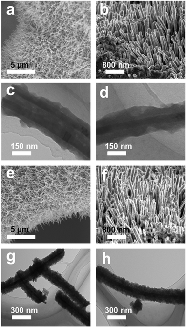 | ||
| Fig. 1 (a and b) SEM images of the NiSe@CoOOH NWs/NF. (c and d) TEM images of NiSe@CoOOH nanowires. (e and f) SEM images of the NiSe@CoP NWs/NF. (g and h) TEM images of NiSe@CoP nanowires. | ||
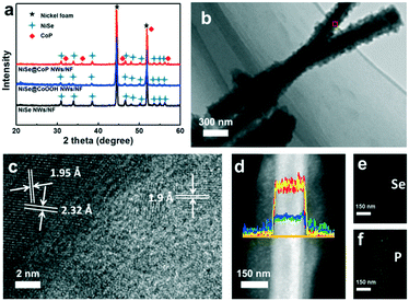
Fig. 2a shows the X-ray diffraction (XRD) patterns for NiSe NWs/NF, NiSe@CoOOH NWs/NF and NiSe@CoP NWs/NF. Obviously, similar diffraction patterns were observed for all materials. The diffraction peaks located at 2θ = 33.7°, 45.2°, 51.5°, 63.1°, and 72.0° could be assigned to the (210), (221), (311), (400), and (024) cubic planes of NiSe (JCPDS no. 09-234), respectively.25 Meanwhile, the diffraction peaks at 2θ = 17.2°, 33.7°, and 58.2° could be indexed to NF (JCPDS no. 73-1508) phase.19 It can be seen that all the NiSe NWs/NF and NiSe@CoOOH NWs/NF had similar XRD patterns and did not exhibit any peak relating to the CoOOH material, and this further indicated that the structures of the shell were amorphous. The XRD patterns for the products, after phosphidation, have shown that besides the XRD patterns for the Ni foam and NiSe, the existence of a new structure with a product corresponding to orthorhombic CoP (JCPDS no. 29-0497) suggests a successful conversion of amorphous CoOOH into CoP.26 Fig. S7† gives the Raman spectra of NiSe NWs/NF and NiSe@CoOOH NWs/NF, respectively. For the NiSe@CoOOH NWs/NF, its Raman spectrum displayed two obvious Raman peaks at 499 and 630 cm−1. The Raman spectrum of NiSe@CoOOH NWs/NF was similar to that previously reported for the amorphous CoOOH species prepared by other routes.27 From this result it can be concluded that the shell was in the amorphous CoOOH phase and was in accordance with the XRD results. A high-resolution TEM (HRTEM) image of the selected area in Fig. 2b shows well-resolved lattice fringes with interplanar distances of 0.273 and 0.259 nm, which can be indexed to the (011) and (200) planes of NiSe, respectively (Fig. 2c and S8†).19 In addition, the HRTEM image also reveals lattice fringes with a d spacing of 0.190 nm, which corresponds to the (211) plane of CoP (Fig. 2c).28Fig. 2d shows the energy-dispersive X-ray (EDX) lines of the NiSe@CoP NWs/NF, and analysis along the cross section of the nanowire reveals higher Ni and Se contents at the centre and higher Co and P contents at both sides, indicating a core–shell structure. The result was further confirmed by the EDX elemental mappings (Fig. 2e and f), which clearly reveal the homogeneous sheath and core and shell distributions of NiSe and CoP, respectively. The energy-dispersive X-ray (EDX) spectrum of these nanocrystals suggests that the cobalt/phosphorus and Ni/Se atomic ratios are close to 1![[thin space (1/6-em)]](https://www.rsc.org/images/entities/char_2009.gif) :
:![[thin space (1/6-em)]](https://www.rsc.org/images/entities/char_2009.gif) 1 (Fig. S6†). These data proved that the NiSe@CoP NWs/NF catalyst with a core–shell heterostructure was prepared successfully.
1 (Fig. S6†). These data proved that the NiSe@CoP NWs/NF catalyst with a core–shell heterostructure was prepared successfully.
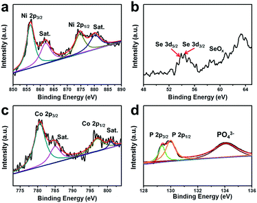
To gain further insight into the surface chemical states and electron interactions of the NiSe@CoP NWs/NF, we characterized the as-prepared sample by X-ray photoelectron spectroscopy (XPS). In Fig. 3a, the two peaks located at 855.4 eV and 873.2 eV can be ascribed to Ni 2P3/2 and Ni 2P1/2, respectively, with two satellites located at approximately 862.3 eV and 879.6 eV because of the existence of surface oxidation on the NiSe nanowires.29 In Fig. 3b, the peak at 54.3 eV is representative of the Se 3d binding energy, indicating a −2 valence of Se, and the weak peak around 59 eV suggests that a small amount of SeO2 had been formed on the surface by oxidation in air.30 The Co 2p3/2 region shows the peaks at 780.4 and 795.5 eV assigned to Co 2p3/2 and Co 2p1/2, respectively, with two satellites located at approximately 798.2 eV and 802.9 eV (Fig. 3c).31 In the XPS spectrum in the P 2p region, the two peaks at 128.7 and 129.6 eV correspond to the P 2p1/2 and P 2p3/2 states in CoP, respectively. The typical peak of oxidized cobalt and phosphorus species is also observed at 134.0 eV, which arises from superficial oxidation due to the catalyst being exposed to air (Fig. 3d).12 The peaks assigned to Co 2p3/2, Co 2p1/2, P 2p3/2 and P 2p1/2 are detected at 780.4, 128.7, 129.3, and 129.7 eV, respectively, which are consistent with CoP in a previous work.32 These results revealed that Co has a small positive charge and P has a small negative charge in the sample, which would be beneficial for the HER activity improvement. Therefore, the transfer of electron density from Co to P of a CoP catalyst is in principle similar to that of the complex catalysts of previously reported results.11
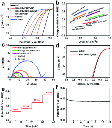
The electrocatalytic activity of the NiSe@CoP NWs/NF for the HER was evaluated at room temperature in 1.0 M KOH solution. The NF, CoP/NF, NiSe NWs/NF, NiSe@CoOOH NWs/NF, and commercial 20% Pt/C catalysts were also tested for comparison. The polarization curves in Fig. 4a show that the NiSe@CoP NWs/NF exhibited an overpotential of 91 mV to achieve a current density of 10 mA cm−2, which is lower than that of NiSe@CoOOH NWs/NF (135 mV), NiSe NWs/NF (160 mV), CoP/NF (182 mV) and NF (218 mV). To gain further insight into the NiSe@CoP NWs/NF electrode, the corresponding Tafel slopes for the above-mentioned catalysts were drawn to investigate the HER kinetics. As shown in Fig. 4b, Tafel slopes of 41, 55, 86, 103, 109, and 126 mV dec−2 are measured for commercial 20% Pt/C, NiSe@CoP NWs/NF, NiSe@CoOOH NWs/NF, NiSe NWs/NF, CoP/NF and NF, respectively. These results clearly indicate that the NiSe@CoP NWs/NF electrode has a low Tafel slope, revealing the favorable kinetics towards electrochemical HER. The Nyquist plots (Fig. 4c) show that the NiSe@CoP NWs/NF possesses a much smaller semicircle compared with that of the other catalysts, which confirms that the NiSe@CoP NWs/NF has an enhanced electron transfer ability of the unique core–shell structure.
Apart from the catalytic activity, long-term durability is also a key property for a HER electrocatalyst. Fig. 4d shows that the NiSe@CoP NWs/NF electrode displays the LSV curves of an initial test and 1000 CV cycles. After long-term cycling, the catalyst shows a polarization curve similar to that obtained previously with a slight decay of the current density. Fig. 4e shows a multistep chronopotentiometric curve for the NiSe@CoP NWs/NF in 1.0 M KOH with very stable potentials throughout the current density change steps from 10 to 100 mA cm−2. The results further demonstrate that the material has high catalytic stability in a wide current range and excellent mass transportation. The stability of our NiSe@CoP NWs/NF was further tested using chronopotentiometric (CP) measurements over extended periods. As reported in Fig. 4f, the 3D electrode showed good electrochemical stability with only very little decay for continuous 12 h tests under harsh running conditions. After the stability tests, we performed SEM, TEM, XPS, and Raman characterization to check the morphology and structural changes of the catalyst. The P XPS spectrum of the post-HER sample (Fig. S10†) shows the increase of the peak intensity for PO43− (near 134.0 eV), which indicates that the P species at the surface of the sample might be further oxidized under such strongly alkaline conditions. In addition, the peak at 971 cm−1 seen in the corresponding Raman spectral analysis further confirms the formation of PO43− on the shell of the post-HER sample (Fig. S11†). Fig. S9† shows the SEM and TEM images of the NP electrode after the HER electrolysis. As can be seen in Fig. S9,† no obvious morphology changes occurred on the electrode after a long-term operation in the HER, suggesting an excellent structure stability of the catalysts. The good stability of the NiSe@CoP NWs/NF should be ascribed to the protective role of the CoP shell that can prevent surface oxidation and corrosion of the NiSe core in a strongly alkaline medium.
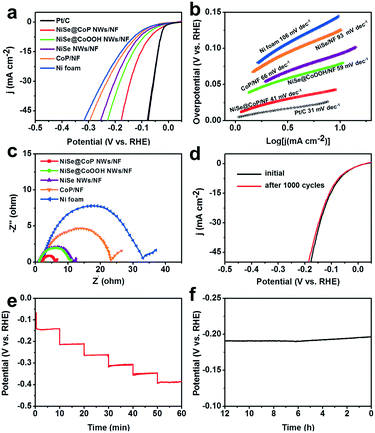
The detailed electrocatalytic HER performance of the NiSe@CoP NWs/NF was also examined in 0.5 M H2SO4 solution, as illustrated in Fig. 5. Fig. 5a depicts the linear sweep voltammetry (LSV) polarization curves of the catalysts. To achieve a current density of 10 mA cm−2, the electrode requires a very small potential of 73 mV. Though it was still higher than that of the Pt/C electrode (47 mV), it was substantially reduced as compared to that of NiSe@CoOOH NWs/NF (97 mV), NiSe NWs/NF (109 mV), CoP/NF (141 mV) and NF (156 mV). To evaluate the HER kinetics of the catalysts, the Tafel slope derived from the polarization curves was implemented, as shown in Fig. 5b. It is also noted that the calculated Tafel slope of NiSe@CoP NWs/NF (41 mV dec−1) is slightly higher than that of Pt/C/NF (31 mV dec−1) but obviously lower than those of the other samples. Because the Tafel slope is directly associated with the reaction kinetics of electrocatalysts, the lower Tafel slope of the NiSe@CoP NWs/NF indicates its faster kinetics and a higher catalytic activity for the HER. Moreover, electrochemical impedance spectroscopy (EIS) measurements (Fig. 5c) show that the NiSe@CoP NWs/NF has a smaller polarization resistance than the other catalysts, which suggests an enhanced electron transfer rate and faster catalytic kinetics of NiSe@CoP NWs/NF.
We further evaluated the stability of the NiSe@CoP NWs/NF electrode for the HER under acidic conditions. As shown in Fig. 5d, negligible degradation was detected in the polarization curves after continuous CV scanning for 1000 cycles in 0.5 M H2SO4 at a scan rate of 50 mV s−1. A multi-step chronopotentiometric curve for the as-prepared NiSe@CoP NWs/NF electrode in 0.5 M H2SO4 with the current density being increased from 25 to 125 mA cm−2 (25 mA cm−2 per 10 min) is presented in Fig. 5e. The potential for every step was tested and gave similar results, which shows that the core–shell NiSe@CoP NWs/NF electrode exhibits excellent mass transport, conductivity, and outstanding mechanical robustness. The stability of the electrode for the hydrogen evolution reaction was further measured by amperometric i–t tests at a constant density of 50 mA cm−2 in 0.5 M H2SO4 solution, and the results are shown in Fig. 5f. The i–t curve of the electrode shows negligible decay during the HER i–t measurement for 12 h, demonstrating the excellent catalytic stability of NiSe@CoP NWs/NF in an acidic medium. The SEM and TEM images of the NiSe@CoP NWs/NF electrode after the HER electrolysis indicate that the NiSe@CoP NWs still covered the NF surface only with some aggregations and the core–shell nanowire structure morphology remained (Fig. S12†). An increase of the peak intensity for SeOx at 134.0 eV was observed from the P 3d XPS core level. The corresponding XPS spectra show that the increase of the peak intensity for PO43− (near 134.0 eV) from the P 2p region could be attributed to the oxidation of the surface (Fig. S13†). Accordingly, the XPS and Raman spectra of the post-HER sample investigations clearly identify the increase of the peak intensity for PO43− on the surface of NiSe@CoP NWs/NF after the HER stability tests (Fig. S14†). These peaks could be attributed to the oxidation of P at the CoP surface under such strongly acidic conditions. The Se XPS analysis for the post-HER NiSe@CoP NWs/NF shows that the main peak of the Se 3d XPS core level is representative of Se2−, indicating that the CoP shell, as a protective shell structure, may protect the core NiSe nanowire from aggregation and surface oxidation during the long-term electrochemical stability tests in strong acidic solutions.
The superior catalytic performance of the NiSe@CoP NWs/NF electrode can be mainly attributed to the following aspects. First, a synergistic combination between the NiSe and CoP in the core–shell structured electrode may account for the enhanced electrocatalytic activity. Second, the 3D core–shell structure with a rough shell can provide more active sites for the catalytic process and protect the core from surface oxidation and corrosion in a strongly alkaline medium. Moreover, the structural advantage of the NiSe@CoP NWs/NF can improve the charge transfer efficiency and conductivity in the catalytic process.
In summary, we have demonstrated the first synthetic construction of the core–shell structured NiSe@CoP NWs/NF through direct phosphorization of the NiSe@CoOOH NWs/NF precursor. As a result of the electron transfer and the unique core–shell structure, the well-designed NiSe@CoP NWs/NF with the synergistic coupling effects demonstrates a superior HER activity with a lower overpotential, a smaller Tafel slope and outstanding stability in both alkaline and acidic media. A current density of 10 mA cm−2 is generated at an overpotential of only 91 mV with a small Tafel slope of 55 mV per decade in 1 M KOH electrolyte, and η10 of 75 mV with an extremely small Tafel slope of 41 mV in an acidic solution (pH = 0). Notably, the NiSe@CoP NWs/NF electrode shows excellent stability evaluated by 1000 potential cycles and operation with a high current density at a fixed potential for 12 h in 0.5 M H2SO4 and 1.0 M KOH, respectively. The facile preparation method and excellent electrocatalytic activity enable this hybrid electrocatalyst to be a promising candidate for future large-scale applications in water splitting. Overall, we believe that our study may provide a new pathway to explore the design of highly efficient HER electrocatalysts.
Conflicts of interest
There are no conflicts to declare.References
- S. Cobo, J. Heidkamp, P. A. Jacques, J. Fize, V. Fourmond, L. Guetaz, B. Jousselme, V. Ivanova, H. Dau, S. Palacin, M. Fontecave and V. Artero, Nat. Mater., 2012, 11, 802 CrossRef CAS PubMed.
- M. W. Kanan and D. G. Nocera, Science, 2008, 321, 1072–1075 CrossRef CAS PubMed.
- M. G. Walter, E. L. Warren, J. R. McKone, S. W. Boettcher, Q. Mi, E. A. Santori and N. S. Lewis, Chem. Rev., 2010, 110, 6446–6473 CrossRef CAS PubMed.
- J. S. Luo, J. H. Im, M. T. Mayer, M. Schreier, M. K. Nazeeruddin, N. G. Park, S. D. Tilley, H. J. Fan and M. Graetzel, Science, 2014, 345, 1593 CrossRef CAS PubMed.
- N. S. Lewis and D. G. Nocera, Proc. Natl. Acad. Sci. U. S. A., 2006, 103, 15729 CrossRef CAS PubMed.
- R. Subbaraman, D. Tripkovic, D. Strmcnik, K. C. Chang, M. Uchimura, A. P. Paulikas, V. Stamenkovic and N. M. Markovic, Science, 2011, 334, 1256 CrossRef CAS PubMed.
- J. Zhang, L. F. Qi, J. R. Ran, J. G. Yu and S. Z. Qiao, Adv. Energy Mater., 2014, 4, 1301925 CrossRef.
- S. Carenco, D. Portehault, C. Boissière, N. Mézailles and C. Sanchez, Chem. Rev., 2013, 113, 7981 CrossRef CAS PubMed.
- C. Tang, R. Zhang, W. Lu, L. He, X. Jiang, A. M. Asiri and X. Sun, Adv. Mater., 2017, 29, 1602441–1602446 CrossRef PubMed.
- P. Liu and J. A. Rodriguez, J. Am. Chem. Soc., 2005, 127, 14871 CrossRef CAS PubMed.
- C. Tang, R. Zhang, W. Lu, Z. Wang, D. Liu, S. Hao, G. Du, A. M. Asiri and X. Sun, Angew. Chem., Int. Ed., 2017, 56, 842–846 CrossRef CAS PubMed.
- C. Tang, L. Gan, R. Zhang, W. Lu, X. Jiang, A. M. Asiri, X. Sun, J. Wang and L. Chen, Nano Lett., 2016, 16, 6617–6621 CrossRef CAS PubMed.
- J. Tian, Q. Liu, A. M. Asiri and X. Sun, J. Am. Chem. Soc., 2014, 136, 7587–7590 CrossRef CAS PubMed.
- T. Liu, D. Liu, F. Qu, D. Wang, L. Zhang, R. Ge, S. Hao, Y. Ma, G. Du, A. M. Asiri, L. Chen and X. Sun, Adv. Energy Mater., 2017, 7, 1700020 CrossRef.
- M. Li, X. Liu, Y. Xiong, X. Bo, Y. Zhang, C. Han and L. Guo, J. Mater. Chem. A, 2015, 3, 4255–4265 CAS.
- N. Jiang, B. You, M. Sheng and Y. Sun, Angew. Chem., Int. Ed., 2015, 54, 6251–6254 CrossRef CAS PubMed.
- Q. Liu, J. Tian, W. Cui, P. Jiang, N. Cheng, A. M. Asiri and X. Sun, Angew. Chem., 2014, 126, 6828–6832 CrossRef.
- D. S. Kong, J. J. Cha, H. T. Wang, H. R. Lee and Y. Cui, Energy Environ. Sci., 2013, 6, 3553–3558 CAS.
- C. Tang, N. Cheng, Z. Pu, W. Xing and X. Sun, Angew. Chem., Int. Ed., 2015, 32, 9351–9355 CrossRef PubMed.
- J. Liang, Y. Yang, J. Zhang, J. Wu, P. Dong, J. Yuan, G. Zhang and J. Lou, Nanoscale, 2015, 7, 14813–14816 RSC.
- F. M. Wang, Y. C. Li, T. A. Shifa, K. L. Liu, F. Wang, Z. X. Wang, P. Xu, Q. S. Wang and J. He, Angew. Chem., Int. Ed., 2016, 55, 6919–6924 CrossRef CAS PubMed.
- X. L. Zhou, Y. Liu, H. X. Ju, B. C. Pan, J. F. Zhu, T. Ding, C. D. Wang and Q. Yang, Chem. Mater., 2016, 28, 1838–1846 CrossRef CAS.
- H. Q. Zhou, Y. M. Wang, R. He, F. Yu, J. Y. Sun, F. Wang, Y. C. Lan, Z. F. Ren and S. Chen, Nano Energy, 2016, 20, 29–36 CrossRef CAS.
- H. Zhou, F. Yu, J. Sun, H. Zhu, I. K. Mishra, S. Chen and Z. Reif, Nano Lett., 2016, 16, 7604 CrossRef CAS PubMed.
- L. Mi, H. Sun, Q. Ding, W. Chen, C. Liu, H. Hou, Z. Zheng and C. Shen, Dalton Trans., 2012, 41, 12595–12600 RSC.
- A. Infantes-Molina, J. A. Cecilia, B. Pawelec, J. L. G. Fierro, E. Rodrguez-Castelln and A. Jimnez-Lpez, Appl. Catal., A, 2010, 390, 253 CrossRef CAS.
- T. Pauporté, L. Mendoza, M. Cassir, M. Bernard and J. Chivot, J. Electrochem. Soc., 2005, 152, C49–C53 CrossRef.
- W. Maneeprakorn, M. A. Malik and P. OBrien, J. Mater. Chem., 2010, 20, 2329 RSC.
- P. Prieto, V. Nistor, K. Nouneh, M. Oyama, M. Abd-lefdil and R. Diaz, Appl. Surf. Sci., 2012, 258, 8807–8813 CrossRef CAS.
- S. Huang, Q. He, W. Chen, Q. Qiao, J. Zai and X. Qian, Chem. – Eur. J., 2015, 21, 4085–4091 CrossRef CAS PubMed.
- A. P. Grosvenor, S. D. Wik, R. G. Cavell and A. Mar, Inorg. Chem., 2005, 44, 8988 CrossRef CAS PubMed.
- E. J. Popczun, J. R. McKone, C. G. Read, A. J. Biacchi, A. M. Wiltrout, N. S. Lewis and R. E. Schaak, J. Am. Chem. Soc., 2013, 135, 9267–9270 CrossRef CAS PubMed.
Footnote |
| † Electronic supplementary information (ESI) available. See DOI: 10.1039/c7cy01606a |
| This journal is © The Royal Society of Chemistry 2018 |

