
Selectivity tuning over monometallic and bimetallic dehydrogenation catalysts: effects of support and particle size†
Konstantinos A.
Goulas‡
 bc,
Yuying
Song
d,
Gregory R.
Johnson§
b,
Justin P.
Chen
abc,
Amit A.
Gokhale¶
be,
Lars C.
Grabow
*d and
F. Dean
Toste
*ac
bc,
Yuying
Song
d,
Gregory R.
Johnson§
b,
Justin P.
Chen
abc,
Amit A.
Gokhale¶
be,
Lars C.
Grabow
*d and
F. Dean
Toste
*ac
aDepartment of Chemistry, University of California, Berkeley, California 94720, USA. E-mail: fdtoste@berkeley.edu
bDepartment of Chemical and Biomolecular Engineering, University of California, Berkeley, California 94720, USA
cEnergy Biosciences Institute, University of California, Berkeley, California 94720, USA
dDepartment of Chemical and Biomolecular Engineering, University of Houston, Houston, Texas 77204, USA. E-mail: grabow@uh.edu
eBASF Corporation, 33 Wood Avenue South, Iselin, NJ 08830, USA
First published on 22nd November 2017
Abstract
The efficacy of tandem dehydrogenation–condensation catalysts for the upgrade of bio-derived intermediates is largely determined by their relative (de-)hydrogenation and decarbonylation activity. Here, the effects of support and particle size of heterogeneous PdCu alloy catalysts on (de-)hydrogenation and decarbonlylation reactions were investigated using kinetic measurements, X-ray absorption spectroscopy and density functional theory (DFT). The chemical mismatch of Cu2+ with Ti4+ and Ca2+ prevents the substitution of Cu into the lattice of TiO2 or hydroxyapatite supports, and facilitates its alloying with Pd, resulting in improved selectivity for hydrogenation–dehydrogenation reactions compared to decarbonylation reactions. Based on kinetic measurements of butyraldehyde reactions over Pd and PdCu/SiO2 model catalysts, decarbonylation activity is attributed to the presence of Pd surface ensembles, while (de-)hydrogenation reactions are catalyzed by PdCu sites on the surface. This is consistent with selectivity and CO coverage trends with increasing conversion, and DFT-based microkinetic modeling. Selectivity control can also be achieved using the PdCu nanocluster size. Smaller nanoparticles favor the C–CO bond scission step of the decarbonylation reaction, due to the stronger binding of CO and alkyl species to sites of lower coordination. CO-induced segregation of reactive Pd atoms to under-coordinated step/edge sites also amplifies the geometric effect on the catalytic behavior.
1. Introduction
Over the past decade, increased awareness about climate change has led to growing interest in conversion of biomass to fuels.1–3 A significant portion of bio-derived feedstocks are oxygenated molecules, and hence, catalytic reactions involving upgrading of such platform molecules have recently garnered great attention.4–8 Direct hydrodeoxygenation of platform molecules affords C5 and C6 molecules, which are suitable for blending with gasoline.9–15However, the production of higher value-added products in the jet and diesel range requires the lengthening of the molecular carbon chain length. To achieve this, a variety of C–C bond formation strategies has been investigated, such as ketonization,16,17 furan condensation18,19 and aldol condensation.20,21 Of particular interest is the tandem dehydrogenation–aldol condensation reaction. In this sequence, alcohols are dehydrogenated to reactive aldehydes and ketones, which in turn undergo aldol condensation to form a longer carbon chain.22,23 This approach is attractive, as the hydrogen produced in the first step is subsequently used to hydrogenate unsaturated intermediates, thereby improving the overall thermodynamics of the process.24 Recently, we have successfully used this methodology to upgrade fermentation-derived mixtures of acetone, butanol and ethanol (ABE) to diesel fuel precursor ketones (Scheme 1),25 using bifunctional metal and basic catalysts.26 In this sequence, butanol and ethanol are dehydrogenated over the metal catalyst. The resulting aldehydes couple in an aldol condensation step over basic catalyst support sites, and the unsaturated ketone products are hydrogenated over the metal catalyst.27
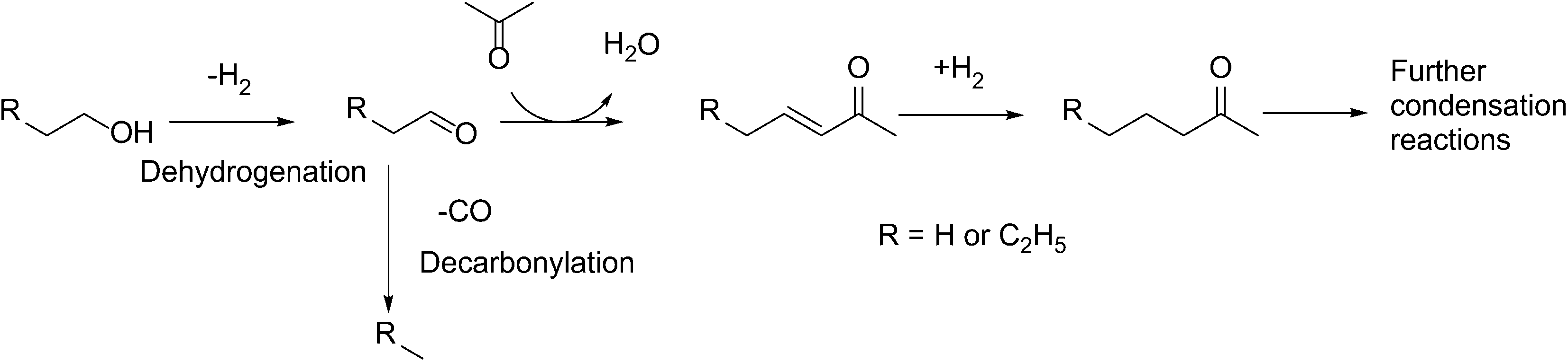 | ||
| Scheme 1 Reactions during acetone–butanol–ethanol (ABE) condensation. | ||
The pervasive challenge in these approaches, however, is the requirement for facile cleavage of C–H bonds, without significant selectivity loss in the form of decarbonylation or esterification reactions. Monometallic catalysts, such as Pd28 and Cu,29 when used for such reactions,30 catalyze the decarbonylation of aldehydes31,32 and the esterification of aldehydes and alcohols, respectively.33–35 In our recent work, we proposed the use of PdCu alloy catalysts to address this issue and we showed that decarbonylation reactions are prevented by the formation of a Cu-rich overlayer on top of PdCu nanoparticles.36
However, there was no effort to investigate the generality of the conclusion for supports other than hydrotalcite and carbon-supported hydrotalcite. Also, the active site requirements for the decarbonylation and dehydrogenation reactions have still not been established.
To address these gaps, the effects of the support and particle size on the selectivity of PdCu and Pd catalysts were investigated in this work. We present experimental data to correlate the extent of alloying with the selectivity of a dehydrogenation–condensation tandem reaction over PdCu catalysts and we show the intrinsic effect of particle size on hydrogenation and decarbonylation reactions. On the basis of these observations, we propose the active sites over which decarbonylation and hydrogenation/dehydrogenation reactions take place.
2. Materials and methods
2.1 Experimental details
![[thin space (1/6-em)]](https://www.rsc.org/images/entities/char_2009.gif) :100. After hydrolysis, the resulting suspension was aged for 16 h at ambient temperature. The solids were separated by filtration and dried in stagnant ambient air at 373 K for 16 h and subsequently treated for 4 h at 723 K (ramp rate 5 K min−1).
:100. After hydrolysis, the resulting suspension was aged for 16 h at ambient temperature. The solids were separated by filtration and dried in stagnant ambient air at 373 K for 16 h and subsequently treated for 4 h at 723 K (ramp rate 5 K min−1).
Hydroxyapatite (HAP) was prepared according to Wang, et al.38 In this process, a stoichiometric quantity of an ammonium hydrogen phosphate (Spectrum Chemical) aqueous solution was added dropwise at ambient temperature to a calcium nitrate (Spectrum Chemical) aqueous solution, whose pH was adjusted to 11 with aqueous ammonium hydroxide solution (Spectrum Chemical). The slurry was aged at 363 K for 1 h and the solids were subsequently filtered and washed with copious amounts of water. The solids were then treated in ambient air at 373 K for at least 16 h and subsequently treated for 4 h at 573 K (ramp rate 5 K min−1).
Carbon-supported hydrotalcite (HT-C) catalysts were prepared as reported in the literature;36 Mg and Al were introduced into activated carbon (Fisher Scientific) using incipient wetness impregnation of an aqueous solution of Mg(NO3)2.6H2O and Al(NO3)3.9H2O, for a 2.9% total oxide loading and 3:1 Mg:Al ratio. The resulting solid was dried in stagnant ambient air at 363 K for 12 h and subsequently treated in flowing He (20 ml min−1 g−1) at 773 K for 4 h (ramp rate 2 K min−1). The PdCu/HT-C material was prepared by incipient wetness impregnation of the Pd and Cu nitrates (Sigma Aldrich) in a 3:1 atomic ratio of Pd to Cu. After impregnation, the solids were dried in stagnant ambient air at 363 K for 12 h and subsequently treated under identical conditions as the support.
PdCu/HAP and PdCu/TiO2, catalysts were prepared by incipient wetness impregnation of the Pd and Cu nitrates (Sigma Aldrich) in a 3:1 atomic ratio of Pd to Cu. After impregnation, the solids were dried in stagnant ambient air at 363 K for 12 h and subsequently treated in stagnant ambient air under identical conditions as the support.
Pd/SiO2 and PdCu/SiO2 catalysts were synthesized following procedures known in the literature: incipient wetness impregnation (IWI) of palladium and copper nitrates into silica gel or strong electrostatic adsorption (SEA) of tetraammine complexes of Pd and Cu onto silica gel.39
In the former method, palladium nitrate hydrate (Sigma Aldrich) was mixed with copper nitrate hemipentahydrate (Sigma Aldrich) and dissolved in a quantity of water equal to that of the pore volume of the silica gel (Sigma Aldrich Davisil grade 636 60–200 mesh). After incipient wetness impregnation, the solids were dried in ambient air at 373 K and subsequently calcined in ambient air at higher temperatures. Catalysts prepared this way were labeled Pd-IWIXXX or PdCu-IWIXXX, where XXX is the calcination temperature in °C.
In the latter method, which was adapted from Miller et al.,39 quantities of palladium nitrate and copper nitrate (enough for 2% Pd loading and a 3:1 Pd:Cu molar ratio) were dissolved in 45 mL of water. To that, 5 g of silica gel was added and the solution was basified with 2 mL of concentrated ammonia solution. The slurry was stirred for 16 h at room temperature and then the solids were filtered away and dried under flowing air at 373 K. Following drying, the solids were calcined under flowing air (100 ml min−1) at different temperatures. Catalysts prepared this way were labeled Pd-SEAXXX or PdCu-SEAXXX, where XXX is the calcination temperature in °C.
:1 ratio by mass and treated in a 10% H2/He mixture, flowing at 100 ml min−1 for 1 h. Following that, the reactants were introduced, either mixtures of acetone, butanol and ethanol (ABE mixture; acetone:butanol:ethanol = 3:6:1 ratio by mass)8 or butyraldehyde. Typical space velocity values ranged from 0.5 to 5 h−1. Experiments were performed at 10 kPa of H2 pressure and 3.7 kPa of reactant pressure unless otherwise noted. In these experiments, gases (99.999% purity) were obtained from Praxair and the liquid reactants were obtained from Sigma Aldrich. Definitions of selectivity, rate and turnover frequency are given in the ESI.†
350 eV, respectively. XAS spectra were recorded at ambient temperature under He after reduction in a 10% H2/He mixture and under reaction conditions identical to those reported above.
Transmission electron microscopy experiments were performed at the TitanX electron microscope at the National Center for Electron Microscopy (PdCu/TiO2, HAP, HT/C and HT samples) or a JEOL JEM 3010 electron microscope at the Keck Center for Advanced Microscopy and Microanalysis at the University of Delaware (PdCu/SiO2 samples). In the former case, the microscope was operated in STEM-EDS mode at 200 kV and the element concentrations were quantified using the Cliff–Lorimer method using the Pd and Cu K peaks. In the latter case, the microscope was operated at 300 kV in bright field mode. No EDS quantification was performed.
Chemisorption experiments were carried out in an ASAP 2920 pulse chemisorption instrument. Samples of the catalyst (∼100 mg) were supported on a plug of quartz wool and reduced at 523 K. After that, they were cooled down to 313 K and CO was pulsed in. The effluent was monitored by a thermal conductivity detector; the pulses were repeated until three consecutive peaks were equal and the dispersion of the catalysts estimated based on a Pds:CO of 2:1.40
Average particle sizes are reported on Table 1.
| Catalyst | d p (nm) |
|---|---|
| PdCu/HAP | 7.5 |
| PdCu/TiO2 | 11.3 |
| PdCu/HT-C | 16 |
| PdCu-SEA400 | 3.3 |
| PdCu-SEA500 | 4.3 |
| PdCu-SEA600 | 5.9 |
| PdCu-IWI600 | 10.1 |
| Pd-IWI400 | 8 |
| Pd-IWI600 | 20 |
| Pd-SEA400 | 1.2 |
| Pd-SEA600 | 2 |
2.2 Theoretical calculations
Density functional theory (DFT) calculations were performed using the Vienna ab initio Simulation Package (VASP)41,42 and the Atomic Simulation Environment (ASE).43 The PW91 generalized gradient approximation (GGA-PW91) was used for exchange and correlation energies.44,45 Core electron interactions were described by projector augmented-wave (PAW) potentials.46,47 The cutoff energy used for expanding the wave function into plane wave basis functions was set to 400 eV and a dipole moment correction was applied in the direction normal to the surface.48 The Gaussian smearing was set to kbT = 0.1 eV (ref. 49) and all reported electronic energies were extrapolated to 0 K.50 The geometric structures were considered converged when the force was below 0.05 eV Å−1. The climbing image nudged elastic band algorithm was used to locate the transition states of each elementary step with a resolution of at least five intermediate images.51 The transition states have a single imaginary mode along the reaction path as confirmed by a frequency analysis in the harmonic oscillator approximation using a Cartesian displacement of 0.01 Å. Calculated frequencies obtained for stable intermediates and transition states were used to estimate zero point energy and entropy corrections included in the microkinetic model, but these corrections are omitted in the potential energy diagrams discussed in the main text.The computationally optimized fcc bulk lattice constants are 3.989 Å for Pd and 3.891 Å for Pd3Cu alloy.36 We used the same (4 × 4) unit cell with 4 × 4 × 1 Monkhorst-Pack k-point sampling49 as reported in our previous work36 to model the (111) facet of Pd and PdCu alloy. These surface models are reproduced for reference in Fig. 1. For the stability assessment of alloy (211) surfaces, we used a (2 × 1) periodic unit cell with a 4 × 8 × 1 Monkhorst-Pack k-point grid. When we studied the thermodynamic stability of the intermediates and calculated transition state energies on (211) surfaces, a (4 × 1) periodic unit cell with 4 × 4 × 1 Monkhorst-Pack k-point sampling was used to accommodate the C3 intermediates. All surface slabs have four layers with the top two layers fully relaxed and the bottom two layers fixed to the bulk truncated position. The vacuum distance between two slabs in the normal direction is 20 Å. All energies in this work are given with respect to the clean surface and the gas phase energies of propanol, H2 and CO.
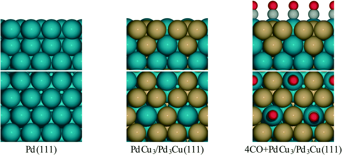 | ||
| Fig. 1 Side and top view for surface models of Pd and PdCu alloy from literature.36 | ||
3. Results and discussion
3.1 Effects of the support on ABE selectivity
Our recent work resulted in the hypothesis that in PdCu/HT catalysts, Cu2+ is trapped in the mixed oxide framework, rendering it less reducible.27,36 We hypothesize that trapping of Cu in the HT materials occurs because of the similar size of the Cu2+ and Mg2+ ions (0.073 nm and 0.072 nm, respectively52) and that a support with a size mismatch between Cu2+ and its cations should not trap Cu. Moreover, TiO225,53 and hydroxyapatite Ca5(PO4)3(OH)54–56 are supports known to catalyze aldol condensation-type reactions and the cations in these materials have sizes significantly different from Cu2+ (Ca2+ has an ionic radius of 0.1 nm and Ti4+ 0.06 nm). Alternatively, a support with a chemical mismatch between the support and the Cu2+ ions, such as carbon, could be employed.36Fig. 2 shows the XANES spectra of the reduced catalysts. Contrary to our observations for HT, the Cu in all three catalysts is in the fully reduced state, based on the edge position and the white line intensity.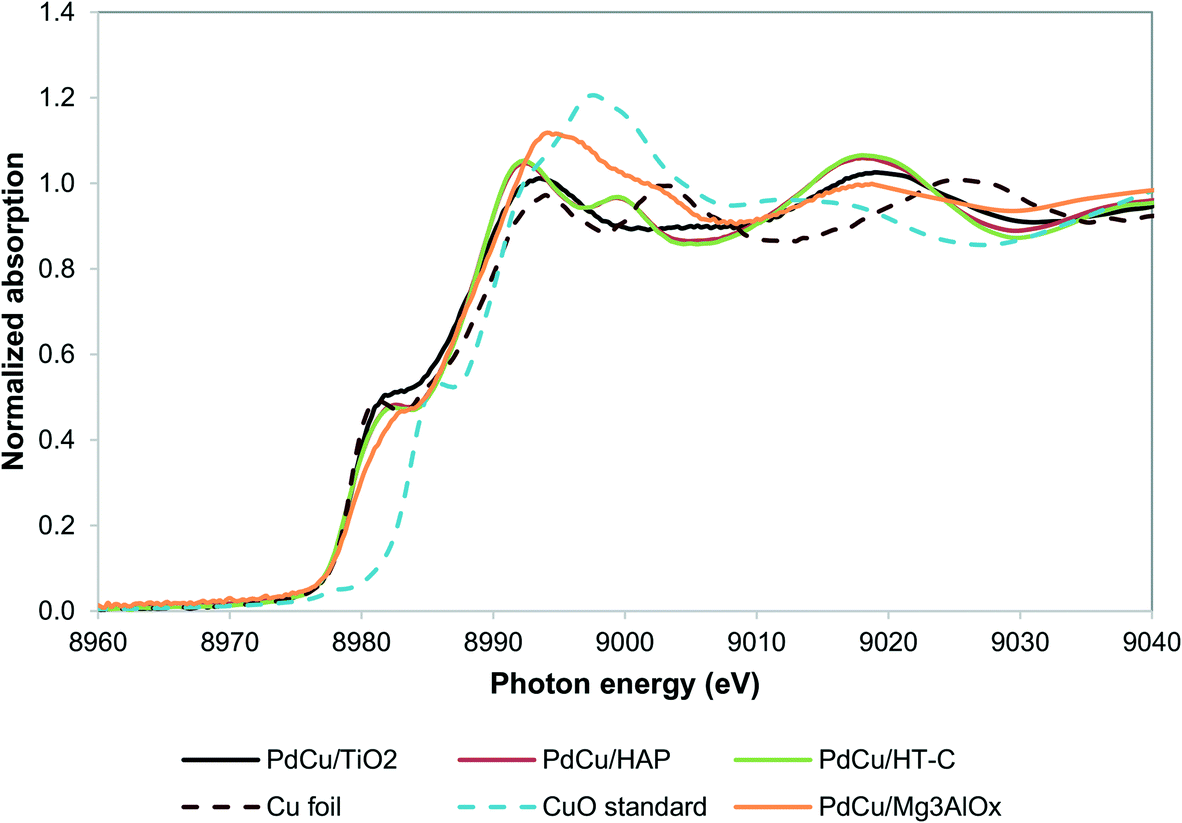 | ||
| Fig. 2 Cu K edge XANES spectra for alternative supports. PdCu/HT-C sample spectrum from literature.36 | ||
When the PdCu/TiO2 and PdCu/HAP catalysts are tested for the ABE reaction (Scheme 1), we observe significant effects on the selectivity and the reactivity as a result of the changes in the catalyst structure, shown in Table 2. In accord with our hypothesis, HT-C, HAP and TiO2 show significantly improved selectivity over HT, as a result of the greater alloying between Pd and Cu.
| Catalyst | Dehydrogenation to decarbonylation ratio | Total ABE condensation rate (μmol gcat−1 h−1) |
|---|---|---|
| PdCu/HT | 3.6 | 145 |
| PdCu/TiO2 | 9.0 | 745 |
| PdCu/HT-C | 49 | 148 |
| PdCu/HAP | 13 | 195 |
Consistent with the results reported by Young et al.,56 the TiO2-supported catalyst showed the highest condensation rate. However, the catalyst comprised of PdCu supported on HT-C showed significantly higher selectivity, compared to the TiO2 and HAP supported catalysts. One of the contributing factors for the difference in the selectivity could be the larger particles in the case of HT-C. TiO2 and HAP have PdCu nanoclusters close to about 11 and 8 nm, while HT-C has 16 nm particles (Table 1). A possible explanation for this behavior can be provided by the consideration that smaller particles have more corner and edge sites, which are known to bind CO more strongly, thereby enhancing decarbonylation over condensation.
3.2 Kinetics of Butyraldehyde reactions over Pd and PdCu catalysts
In order to test the hypothesis that corner and edge sites are responsible for decarbonylation, and also to better understand the reaction mechanisms over PdCu catalysts in the absence of support effects, the kinetics and particle size effects of SiO2-supported catalysts on the decarbonylation and hydrogenation of butyraldehyde (Scheme 2) were examined. Aldehydes are the reactive intermediates in the dehydrogenation–aldol condensation reactions in the Guerbet and ABE chemistry. Hence, determining the relative rates of the alcohol dehydrogenation to butyraldehyde and its decarbonylation to propylene and propane as a function of the particle size and the reactant pressures will enable a more predictive approach to further catalyst discovery efforts in the context of oxygenate chemistry.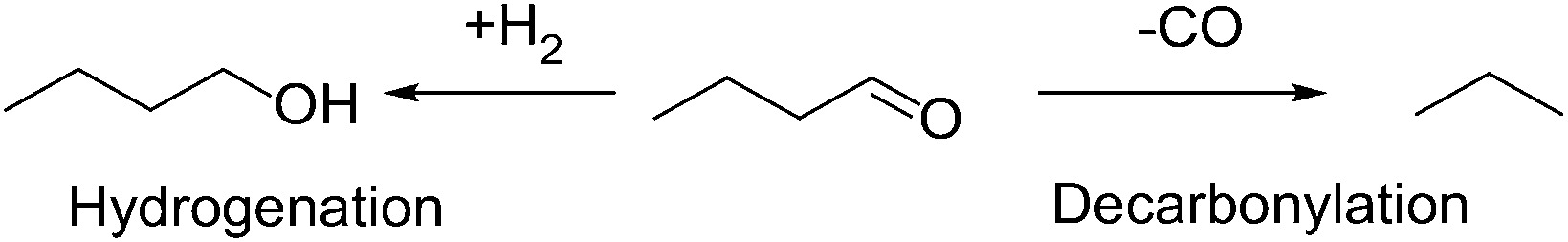 | ||
| Scheme 2 Possible reaction pathways for butyraldehyde over metal catalysts in the presence of H2. | ||
3.3 Characterization of Pd/SiO2 and PdCu/SiO2 catalysts
Citing the extensive literature that has been published on particle size control of SiO2 supports, this inert support was chosen for our studies.36 SiO2 is a poor catalyst for aldol condensation, as the basic sites on its surface are weak,24 thereby enabling us to focus exclusively on the reactions catalyzed by the metallic catalysts. Moreover, Si4+ is very different in size from Cu2+,52 and as such, is not expected to trap Cu2+. This hypothesis is supported by the observation that Cu was completely reduced under reaction conditions, based on the XANES edge line position, which coincides with that of the Cu foil standard (Fig. S1†). As expected, based on the reducibility of PdO and CuO, the Pd was also completely reduced in all SiO2-supported catalysts (Fig. S2†). From fitting the Pd edge EXAFS (Table 3) we found that as the calcination temperature increased and the preparation method changed from SEA to IWI, the coordination number of Pd increased and the interatomic distances increased. On the other hand, the Debye–Waller factor (σ2) decreased. These observations are consistent with an increase of metal nanoparticle size. Also, the ratio of Cu:Pd in the Pd coordination sphere changed from the nominal 0.33 to about 0.2. This data suggests that in the catalyst with the largest nanoparticles, Pd and Cu are segregated,57 consistent with the model put forth in our previous work.32
| Catalyst | PdCu-SEA400 | PdCu-SEA500 | PdCu-SEA600 | PdCu-IWI600 | PdCu-IWI600-reaction |
|---|---|---|---|---|---|
| N Pd–Pd | 7.200 | 7.605 | 8.917 | 9.787 | 8.887 |
| N Pd–Cu | 2.634 | 2.457 | 1.946 | 1.972 | 1.958 |
| N Pd–Pd/NPd–Cu | 2.67 | 3.10 | 4.58 | 4.96 | 4.54 |
| Total CN | 9.834 | 10.112 | 10.963 | 11.769 | 10.845 |
| R Pd–Pd (Å) | 2.696 | 2.709 | 2.722 | 2.724 | 2.716 |
| R Pd–Cu (Å) | 2.621 | 2.626 | 2.638 | 2.643 | 2.633 |
| σ 2 (× 104) | 106 | 100 | 68 | 73 | 103 |
This conclusion is also consistent with the TEM work shown in Table 1. Catalysts prepared by SEA showed much higher dispersions than those prepared by IWI, as has been reported in the literature.36 For example, for a calcination temperature of 873 K, the particle size for the PdCu catalyst prepared by SEA was 5.9 nm, while that for the catalyst prepared by IWI was 10.2 nm. Increasing the calcination temperature also resulted in increased particle size. The sizes of the monometallic Pd catalysts synthesized as controls are also shown in Table 1.
3.4 Effects of residence time
When butyraldehyde was fed over Pd and PdCu catalysts, the reaction rates decreased with increasing residence time. Representative trends are shown in Fig. 3A and B, for Pd and PdCu, respectively. This decrease, which is much more pronounced for Pd and the decarbonylation reactions, likely reflects the fact that the CO resulting from the C–C bond scission binds more strongly on Pd sites, hence preferentially inhibiting the decarbonylation reaction. This is consistent with previous experimental studies using TPD,58–60 as well as theoretical investigations.61 Extrapolation of the observed trends to zero conversion of butyraldehyde in Fig. 3 gives an intrinsic measure of the turnover frequency of the catalyst. All rates reported henceforth will therefore be the results of the extrapolation to zero conversion.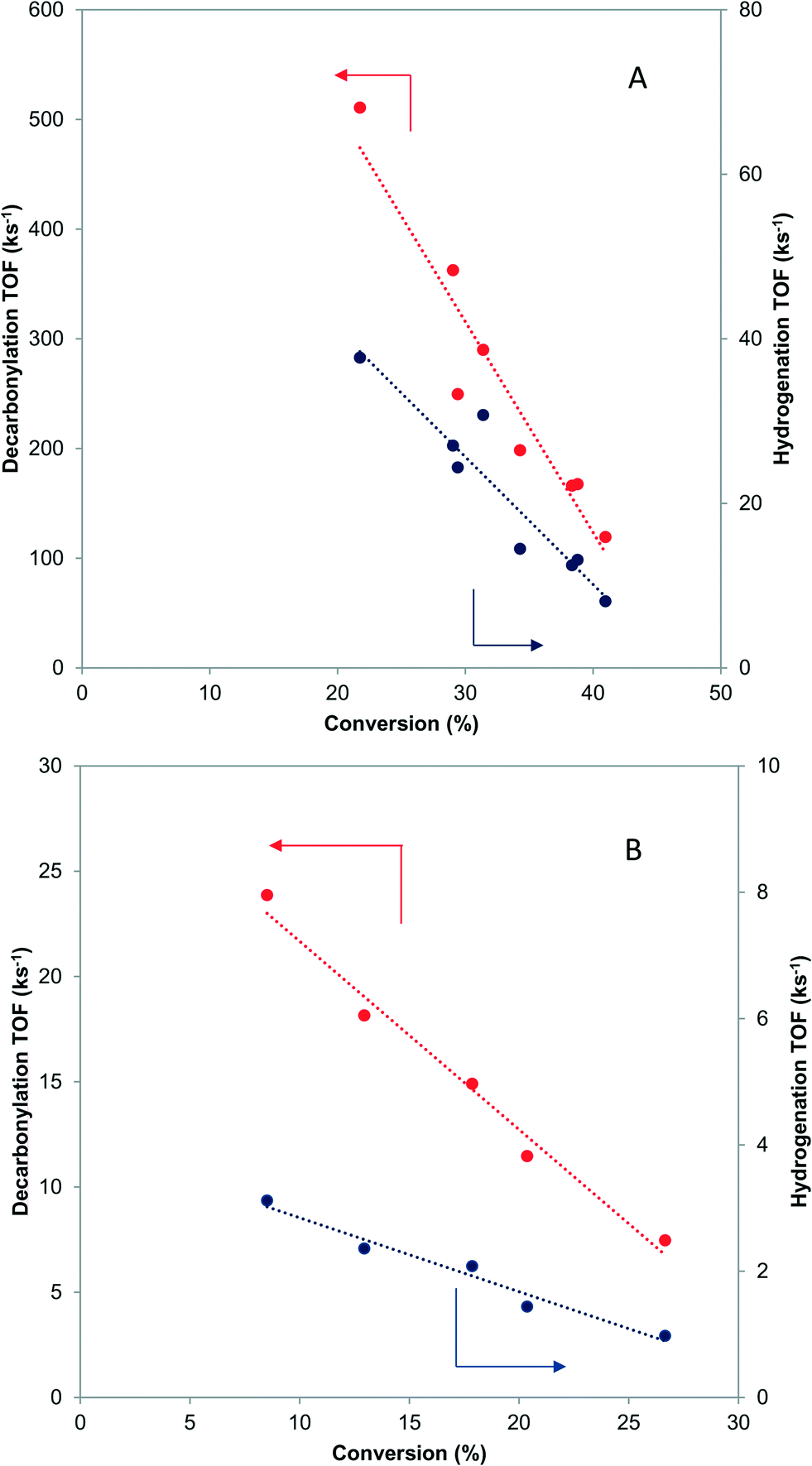 | ||
| Fig. 3 Effects of residence time on the turnover frequency of decarbonylation and hydrogenation over Pd-IWI400 (A-8 nm average particle size) and PdCu-SEA600 (B-5.9 nm average particle size). 473 K, 3.7 kPa butyraldehyde, 10 kPa H2. | ||
3.5 Microkinetic modeling study of effects of residence time
To provide theoretical support for the effect of CO coverage, we built micro-kinetic models to compare the reaction rates of hydrogenation and decarbonylation pathways under different aldehyde conversion conditions. This model was guided by our previously published work,36 but was refined with additional DFT calculations to determine activation barriers for decarbonylation and hydrogenation steps. As before, propanal was used as the probe molecule for aldehydes to keep the problem computationally tractable while maintaining the reactivity and selectivity trends of the reactant.36 The Pd(111) surface was used to model Pd catalysts, while PdCu3/Pd3Cu(111) and 4CO + PdCu3/Pd3Cu(111) surfaces were used to model PdCu catalyst under low and high conversions. As depicted in Fig. 1, all exposed Pd atoms of the 4CO + PdCu3/Pd3Cu(111) model are blocked by CO molecules. We consider these CO molecules spectators that modify the surface properties, but do not participate in the reaction. As such, the surface coverage reported for the microkinetic analysis of this surface is referenced to the available Cu sites only.A comparison of the activation barriers between dehydrogenation and decarbonylation (in Fig. 4) provided a first glance of the relative activities of these two pathways. For example, the activation barrier for decarbonylation on the 4CO + PdCu3/Pd3Cu(111) surface is much larger than the barrier for hydrogenation, implying that hydrogenation should be dominant. However, a more detailed analysis based on a microkinetic model at reaction conditions of T = 473 K and P = 1 bar with 6.9% propanal and 93.1% H2 allows for firmer conclusions.
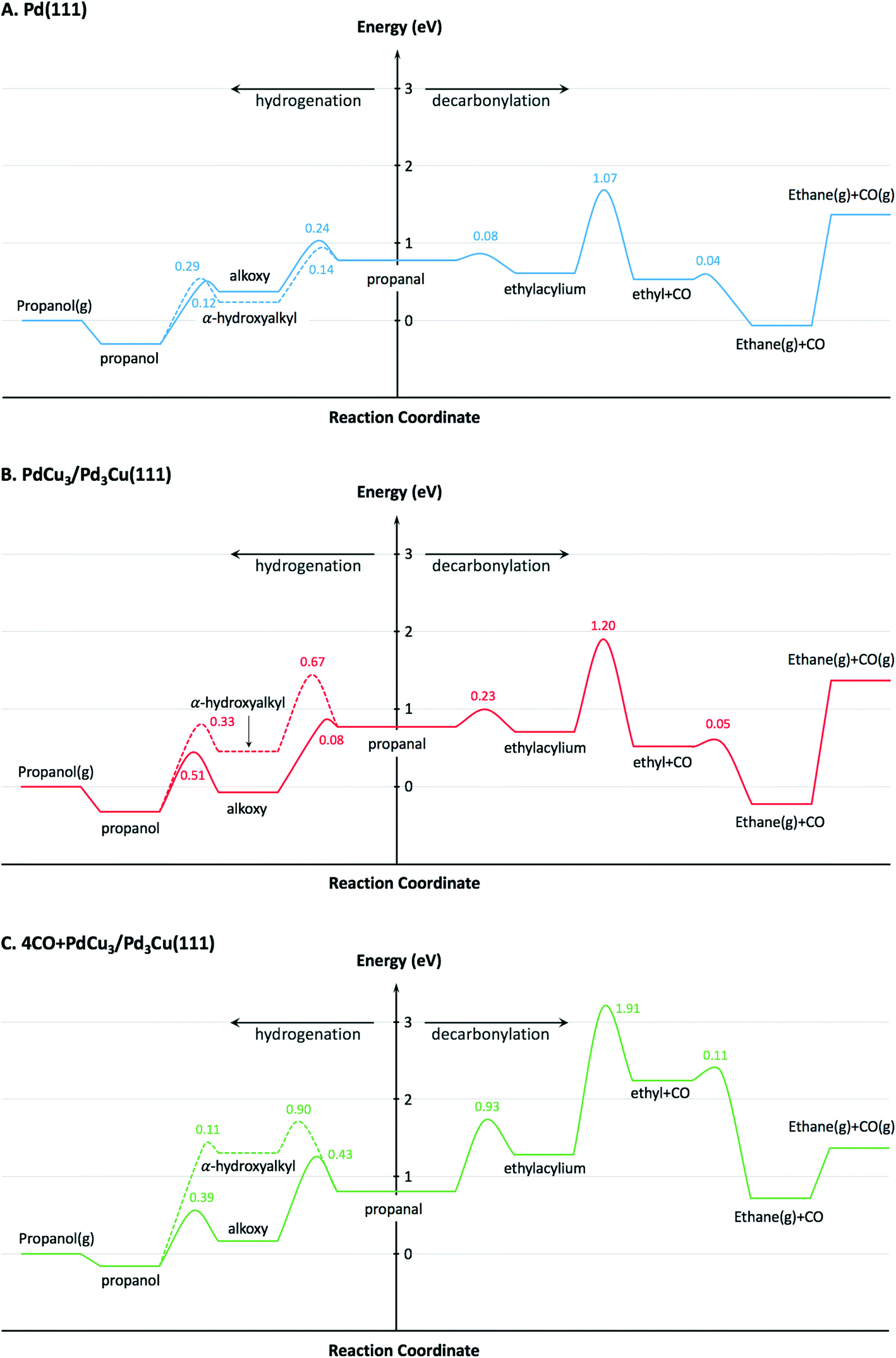 | ||
| Fig. 4 Potential energy diagrams for hydrogenation and decarbonylation of propanal on (A) Pd(111), (B) PdCu3/Pd3Cu(111), and (C) 4CO + PdCu3/Pd3Cu(111) surface models. Energies are reported with respect to the reference surface and gas-phase propanol, CO and H2. Values near transition states indicate activation energy barriers in eV. Solid lines correspond to the decarbonylation and alkoxy-mediated hydrogenation pathways, while the dashed line corresponds to the α-hydroxyalkyl pathway. | ||
The microkinetic model itself consists of the elementary steps shown below:
| Adsorption Steps RCH2CHO(g) + 2* ⇌ RCH2CHO** | (I) |
| H2(g) + 2* ⇌ 2H* | (II) |
| Hydrogen Steps RCH2CHO** + H* ⇌ RCH2CHOH** + * | (III) |
| RCH2CHOH** + H* ⇌ RCH2CH2OH* + 2* | (IV) |
| RCH2CHO** + H* ⇌ RCH2CH2O* + 2* | (V) |
| RCH2CH2O* + H* ⇌ RCH2CH2OH* + * | (VI) |
| RCH2CH2OH* ⇌ RCH2CH2OH(g) + * | (VII) |
| Decarbonylation Steps RCH2CHO** + * ⇌ RCH2CO** + H* | (VIII) |
 | (IX) |
 | (X) |
| CO* ⇌ CO(g) + * | (XI) |
The adsorption of propanal, α-hydroxyalkyl and ethylacylium intermediates was assumed to require two surface sites, based on the adsorption geometry. The microkinetic models were implemented in CatMAP,62 and the reaction rates were obtained numerically under the steady state approximation. The zero point energy for all species was estimated from calculated frequencies obtained in the harmonic oscillator approximation. The temperature-dependent entropy and enthalpy corrections for all surface intermediates are calculated from the vibrational partition function, while gas phase corrections are estimated from the Shomate equation.
The calculated turnover frequencies (TOF) for hydrogenation and decarbonylation pathways as a function of aldehyde conversion are shown in Table 4. Consistent with experimental observations, decarbonylation was significantly faster than hydrogenation on the Pd(111) surface. The TOFs for both pathways simultaneously decrease with increasing conversion, which coincides with increasing CO coverage and is congruent with surface site blocking. Thus, this model supports the hypothesis that longer residence times result in higher CO coverage, fewer active sites, and ultimately lower reaction rates.
| Conversion | Hydrogenation TOF (s−1) | Decarbonylation TOF (s−1) | CO coverage | |
|---|---|---|---|---|
| Pd(111) | 0% | 9.8 × 10⁻⁵ | 44.4 | 0.00 |
| 10% | 1.1 × 10⁻⁶ | 0.7 | 0.18 | |
| 20% | 1.7 × 10⁻⁷ | 0.1 | 0.18 | |
| PdCu3/Pd3Cu(111) | 0% | 1.5 × 10⁻³ | 2.1 | 0.00 |
| 10% | 1.3 × 10⁻⁶ | 2.8 × 10⁻³ | 0.65 | |
| 4CO + PdCu3/Pd3Cu(111) | 10% | 1.1 | 8.0 × 10⁻⁹ | 0.00 |
To describe the catalytic performance of the PdCu alloy catalyst at low conversion we initially considered the clean PdCu3/Pd3Cu(111) alloy surface. We identified the single Pd atom in the surface of this model as the active site for the hydrogenation and decarbonylation pathways. Similar to what has been observed for the Pd(111) surface, decarbonylation is faster than hydrogenation, but the PdCu3/Pd3Cu(111) alloy surface has decreased decarbonylation and increased hydrogenation activity. We attribute the selectivity shift toward hydrogenation to the lack of adjacent Pd sites on the Cu-rich surface of PdCu3/Pd3Cu(111). The dominant Pd–Cu sites are not as active as Pd–Pd pairs for C–CO cleavage.
At 10% conversion the microkinetic model results in Table 4 indicate that 65% of surface Pd sites of PdCu3/Pd3Cu(111) are poisoned by CO and unavailable as active catalytic sites. As we argued in our earlier work32 the CO-modified model, 4CO + PdCu3/Pd3Cu(111), which tracks the CO poisoning effect, is more appropriate in this case. In the refined DFT model, we assumed that the surface Pd sites are always covered by CO molecules and only the accessible Cu sites are available for catalysis. We previously compared the potential energy diagrams given for PdCu3/Pd3Cu(111) and 4CO + PdCu3/Pd3Cu(111) in Fig. 4(B and C) for the hydrogenation pathway, and posited that the absence of significant activity changes is related to the ability of Cu sites to stabilize the alkoxy intermediate binding through its O atom.36 We have here augmented these results with activation barriers along the decarbonylation pathway and find that the C–CO bond cleavage barrier increases from 1.2 to 1.91 eV upon CO-modification. Consequently, the 4CO + PdCu3/Pd3Cu(111) model predicts rapid hydrogenation, but no decarbonylation activity (Table 4). Overall, the microkinetic model analysis leads to the qualitative conclusion that (i) increased conversion leads to higher CO coverage; (ii) higher CO coverage reduces the activity of monometallic Pd; (iii) PdCu alloy formation favors hydrogenation; and (iv) the formation of Pd surface ensembles should be minimized to eliminate decarbonylation reactions.
3.6 Effects of particle size on selectivity
Fig. 5A shows the dependence of the ratio of decarbonylation to hydrogenation on the Pd and PdCu particle size extrapolated to 0% conversion. It is clear that smaller particles favor decarbonylation, while larger ones favor hydrogenation reactions. The ratio changes from about 40, for the smallest particles, to about 5, for the largest particles. Notably, the most substantial changes are observed for particles <5 nm, for which a significant fraction of under-coordinated step sites exits. Interestingly, there was seemingly no difference between the Pd and PdCu catalysts. A likely reason for the similar catalytic behavior observed with both Pd and PdCu surfaces that are clean of CO, as is the case at zero conversion, is that the reactivity is dominated by available Pd surface sites.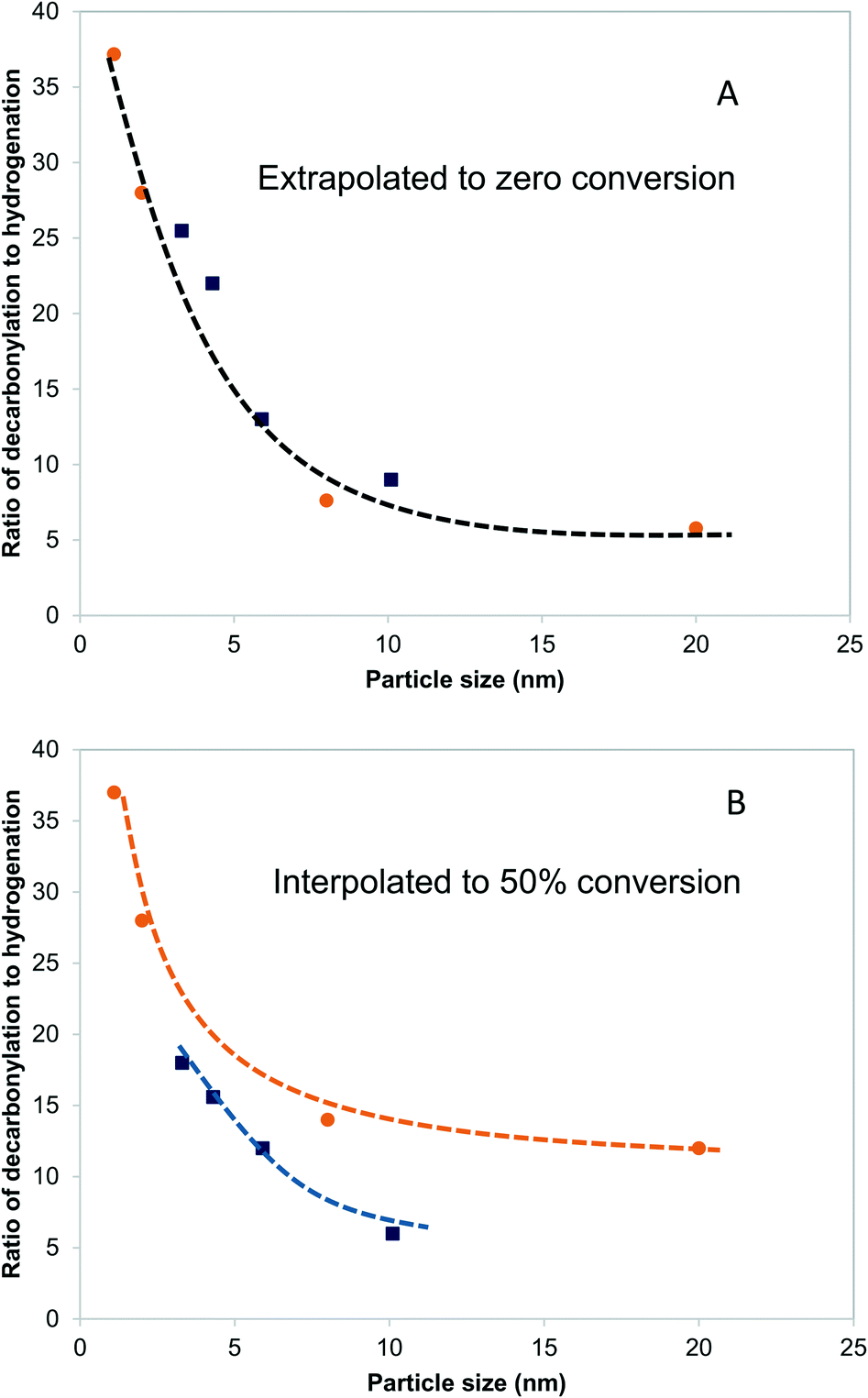 | ||
| Fig. 5 Effects of particle size on the ratio of decarbonylation to hydrogenation over Pd/SiO2 (orange circles) and PdCu/SiO2 catalysts (blue squares). 473 K, 3.7 kPa butyraldehyde, 10 kPa H2. In (A), each point was obtained by extrapolating the ratio of decarbonylation to hydrogenation to zero conversion. In (B), all ratios are obtained by interpolating the experimental measurements to 50% conversion. Dashed lines indicate qualitative trends. | ||
A different picture emerges if one compares the ratios at higher conversions, as shown in Fig. 5B. The ratios of decarbonylation to hydrogenation were much lower in the case of the PdCu catalysts. In those catalysts, the ratio of decarbonylation to hydrogenation decreased with increasing conversion, contrary to the Pd-based catalysts, in which the decarbonylation to dehydrogenation ratio was nearly independent of the conversion, as can be seen by comparing Fig. 5A and B.
3.7 First principles analyses of particle size effects
To understand the molecular-level drivers for the observed particle size effects the structure sensitivity of the key reaction steps was studied. To this end, we first analyzed the microkinetic models for Pd(111) and 4CO + PdCu3/Pd3Cu(111), both representative of large catalyst particles, to determine the rate and selectivity controlling steps as assessed by Campbell's degree of rate control (Table S1†).63 For both model surfaces the decarbonylation rate was limited by the C–CO cleavage step (IX). The hydrogenation pathway is controlled by α-hydroxyalkyl hydrogenation to form propanol on Pd(111), step (IV), and propanal hydrogenation to alkoxy as the key intermediate on 4CO + PdCu3/Pd3Cu(111), step (V). Assuming that the nature of the rate determining steps (RDS) is preserved as the particle size decreases, we focus our following DFT efforts on the energetics of reactions (IV), (V), and (IX) using suitable step models to approximate small Pd and PdCu alloy particles.The obvious choice for monometallic Pd catalyst is the stepped Pd(211) surface and the calculated potential energy diagram is compared to Pd(111) results in Fig. 6A. As commonly observed, the stepped surface binds all species more strongly than the terrace. In addition the C–H bond formation step has a 0.23 eV lower activation barrier and is 0.12 eV more exothermic on the Pd(111) terrace, whereas the C–CO bond scission has a 0.14 eV smaller barrier and is 0.40 eV more exothermic on the Pd(211) step site. These results follow the general rule of thumb that under-coordinated step sites favor bond breaking steps (i.e., decarbonylation), while terrace sites promote bond forming reactions (i.e., hydrogenation). Therefore, we anticipate that identical qualitative conclusions could be drawn if the competitive hydrogenation via the alkoxy intermediate were to occur on step sites. These computational findings are in good agreement with the observed trend of TOF versus particle size (Fig. S3†). The increasing hydrogenation TOF with increasing particle size is consistent with the lower activation barrier over terrace sites. Conversely, the independence of the TOF for decarbonylation from the particle size is consistent with the similarity of reaction barriers over terrace (Ea = 1.07 eV) and stepped (Ea = 0.93 eV) sites.
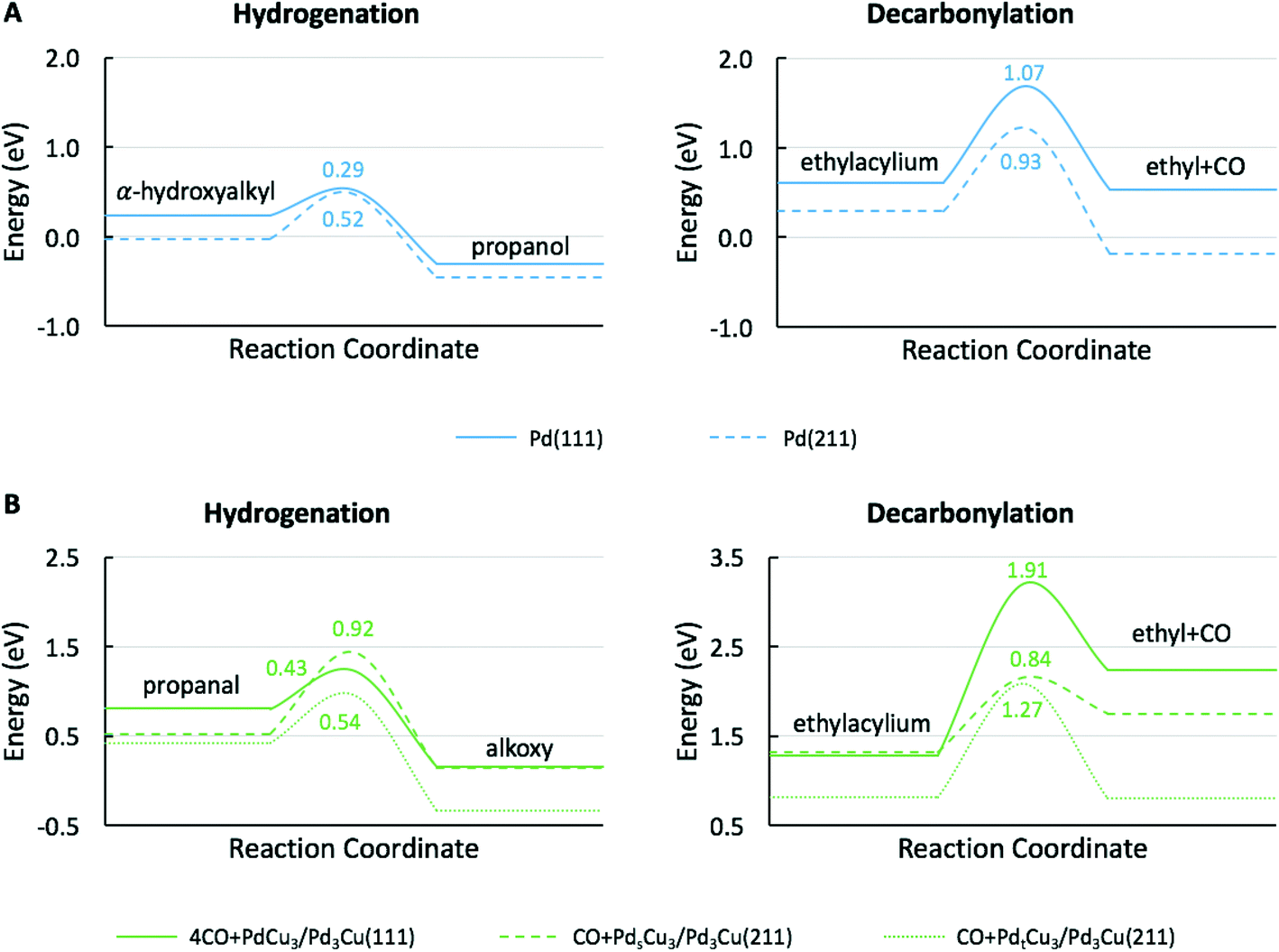 | ||
| Fig. 6 Potential energy diagrams for the (A) Pd-catalyzed hydrogenation of α-hydroxyalkyl to propanol and decarbonylation of ethylacylium to ethyl and CO, and (B) PdCu alloy catalyzed hydrogenation of propanal to alkoxy and decarbonylation of ethylacylium to ethyl and CO. Energies are reported with respect to the reference surface, propanol, CO and H2. Values near transition states indicate activation energy barriers in eV. | ||
For PdCu catalyst, a step model with a composite of Pd3Cu in the bulk and Cu-enriched in surface is used (Fig. 7). This model approximates the composition of PdCu3/Pd3Cu(111) surface (vide supra) and is referred to as the Pdt/sCu5/Pd3Cu(211) surface. Here, the subscripts ‘t’ and ‘s’ indicate Pd placement at a terrace or step site, respectively. To determine the thermodynamically preferred surface position of the surface Pd atom, we assessed its stability by calculating the surface formation energies for different step terminations. In the absence of CO, the lowest-energy stepped surface places the Pd atom at the terrace site position (PdtCu5/Pd3Cu(211)), indicating a modest tendency of Cu to segregate to sites of lower coordination, consistent with our earlier models.
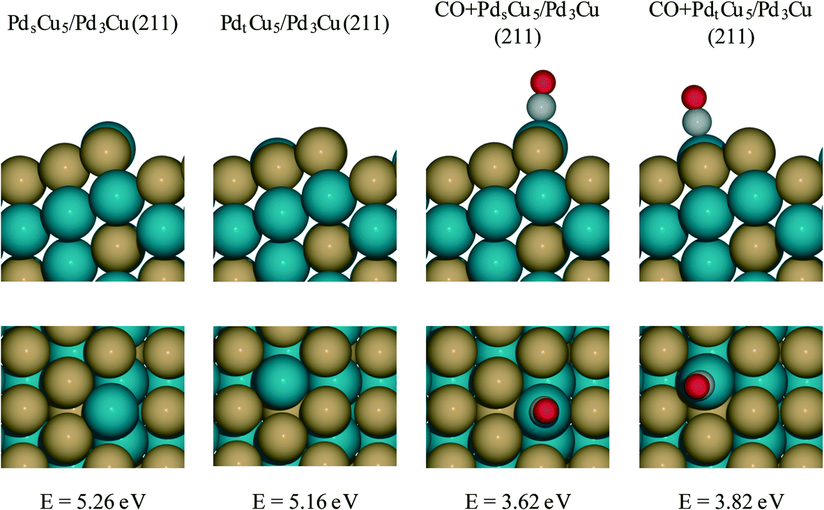 | ||
| Fig. 7 PdCu alloy step models. All surfaces are Cu segregation models constructed as composite of a top layer with PdCu5 stoichiometry and bulk Pd3Cu. In the PdsCu5/Pd3Cu(211) and CO + PdsCu5/Pd3Cu(211) models Pd atoms in the top layer are located at the upper edge position of the steps; in the PdtCu5/Pd3Cu(211) and CO + PdtCu5/Pd3Cu(211) models Pd atoms in the top layer are located on the terrace. The CO + PdsCu5/Pd3Cu(211) and CO + PdtCu5/Pd3Cu(211) models account for CO poisoning of exposed Pd sites. The corresponding surface formation energies for each model are indicated in the figure. These surface formation energies are calculated with respect to bulk Pd atoms, bulk Cu atoms and CO(g). | ||
To create a step-site analogue of the 4CO + PdCu3/Pd3Cu(111) terrace model, as it would be expected under reaction conditions when CO is present, CO was absorbed onto the exposed Pd atom and formed the CO + Pdt/sCu5/Pd3Cu(211) step model. In the presence of CO, the Pd atom prefers the upper edge position of the stepped surface (CO + PdsCu5/Pd3Cu(211)). This structure is 0.2 eV more stable than the structure in which Pd lies at the terrace position (CO + PdtCu5/Pd3Cu(211)). The strong binding of CO to Pd provides the thermodynamic driving force for the segregation of Pd to sites of lower coordination and the final structure is consistent with the experimental observation of lower Pd–M coordination numbers under reaction conditions (Table 3, last two columns).
Fig. 6B shows the comparison of the rate-determining hydrogenation and decarbonylation reactions on both CO + Pdt/sCu5/Pd3Cu(211) step models with Pd at the terrace or step site with the 4CO + PdCu3/Pd3Cu(111) terrace surface. For the less stable CO + PdtCu5/Pd3Cu(211) model we observe a similar undercoordination effect of the Cu atoms at the step site as we discussed for monometallic Pd: at the undercoordinated Cu step atoms all intermediates bind stronger, the bond-making hydrogenation step becomes more activated, and the C–CO bond-breaking step is more favorable than on the 4CO + PdCu3/Pd3Cu(111) terrace model.
More interesting, however, is the fact that CO-induced Pd segregation to the step site greatly enhances the pure geometric effect. When we consider the CO + PdsCu5/Pd3Cu(211) surface, which is thermodynamically more stable in the presence of CO and results in a lower Pd–M coordination number – consistent with EXAFS data on the PdCu-IWI600 sample before and during reaction (Table 3), the activation barrier for C–H bond formation reaches 0.92 eV, the highest value we report herein. At the same time, the C–CO bond cleavage barrier is reduced to only 0.84 eV, which is even lower than that on the Pd(211) surface. We attribute this substantial change to the direct involvement of dynamically accessible Pd step atoms. During the C–CO cleavage reaction, the CO molecule moves from a Pd step site to the neighboring Pd–Cu bridge site due to the repulsive force from decarbonylation intermediates and gives ethylacylium access to the highly active, undercoordinated Pd site for faster decarbonylation. Consequently, CO-induced Pd segregation from terrace to step sites is expected to enhance the ratio of decarbonylation to hydrogenation beyond what would be anticipated from geometric effects only; Merte et al. reported similar behavior in Pt/FeOx systems, in which CO-induced migration of Pt formed highly active sites on the surface for CO oxidation.64 Further support for the proposed segregation behavior is provided by the particle size trends in Fig. 5. At zero conversion, CO-induced segregation does not occur and Pd and PdCu catalysts are only subject to geometric effects. In contrast, at 50% conversion the ratio of decarbonylation to hydrogenation is a much stronger function of particle size for the PdCu alloy than for the monometallic Pd catalyst, which is consistent with our proposed CO-induced Pd segregation model.
3.8 Determination of active site
Further information about the nature of the active site can be obtained by investigating the dependence of the reaction on the reactant pressure. Over a representative Pd catalyst (Fig. 8A), the hydrogenation rate and the decarbonylation rate followed similar trends with butyraldehyde partial pressure. After an initial increase, the rates dropped at pressures higher than 3.7 kPa of butyraldehyde. This behavior is consistent with butyraldehyde, or species derived from it, becoming the most abundant surface intermediate and covering the surface of the catalyst. Based on this, and the fact that the ratio of the reaction rates was independent of the butyraldehyde pressure, we surmised that over Pd, the hydrogenation and decarbonylation reactions are both intrinsically first order in butyraldehyde and require the presence of two identical adjacent sites.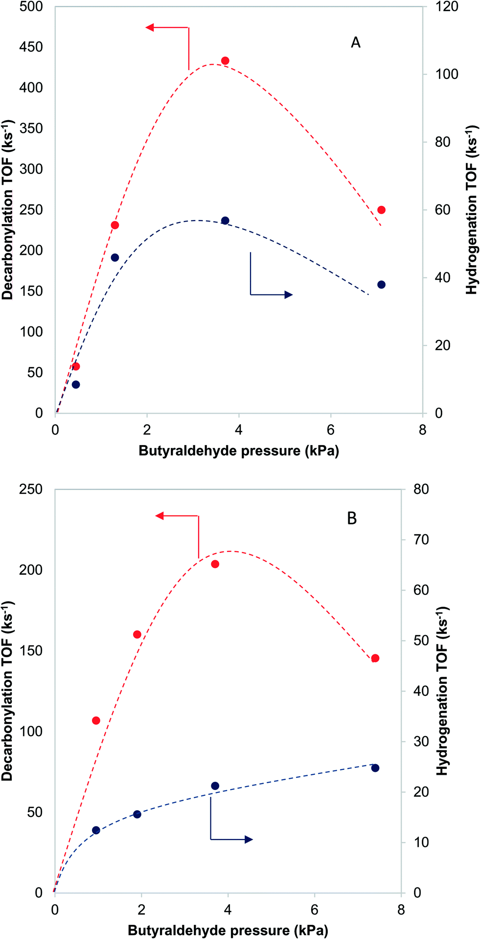 | ||
| Fig. 8 Effects of the reactant pressure on the decarbonylation and hydrogenation reactions over Pd-IWI400 (A – 8 nm nanoclusters) and PdCu-SEA600 (B – 5.9 nm nanoclusters). Dashed lines indicate qualitative trends. 473 K, 10 kPa H2. | ||
On the other hand, over a PdCu catalyst (Fig. 8B), the hydrogenation and decarbonylation rates followed different patterns. Decarbonylation rates followed a similar trend as with the Pd catalyst, decreasing after 3.7 kPa, while hydrogenation rates increased with increasing pressure over the entire experimental range. These observations suggest that over the PdCu catalysts, the decarbonylation and hydrogenation reactions were catalyzed by different sites. This hypothesis is also consistent with the observation that the selectivity changes with changing conversion (Fig. 9). The nature of these sites can be probed by investigating the dependence of the reaction rates on the temperature.
 | ||
| Fig. 9 Effects of conversion on the decarbonylation to hydrogenation ratio over A: PdCu-SEA600 (5.9 nm) and B: Pd-IWI600 (20 nm) catalysts. 473 K, 3.7 kPa butyraldehyde, 10 kPa H2. | ||
The Arrhenius plots for decarbonylation and hydrogenation over Pd and PdCu catalysts (see ESI,† Fig. S4 and S5) were used to calculate the apparent activation energies for the two reactions, shown in Table 5. The fact that the apparent activation energies for decarbonylation are almost equal for Pd and PdCu suggest that Pd–Pd ensembles are responsible for the decarbonylation reaction. The activation energy measured (99 kJ mol−1) matches the one calculated using the DFT models (1.07 eV for a terrace vs. 0.93 eV for a stepped site). On the other hand, the activation energy for hydrogenation over PdCu catalysts is consistent with the calculated activation barriers over the Pd and PdCu terraces.
| Catalyst/reaction | E A,Decarbonylation (kJ mol−1) | E A,Hydrogenation (kJ mol−1) |
|---|---|---|
| Pd | 100 | 11 |
| PdCu | 99 | 41 |
4. Conclusions
In summary, we have studied the hydrogenation and decarbonylation of butyraldehyde over PdCu alloy catalysts as surrogate system for the ABE condensation reaction. We demonstrated a strategy to obtain selective and active PdCu alloy catalysts by using a support that does not incorporate Cu as Cu2+ ions, such as TiO2 or SiO2, and using larger particle sizes. EXAFS evidence points to the alloying of Pd and Cu as the primary requirement for the improved selectivity towards (de)hydrogenation. Subsequent experimental and DFT-based micro-kinetic investigations of model PdCu catalysts shows that the decarbonylation of butyraldehyde takes place over Pd–Pd ensembles situated on terrace or step sites, while (de)hydrogenation reactions take place preferentially over terrace PdCu ensembles. With increasing conversion, Pd surface sites become blocked by strongly adsorbed CO, leading to a general loss in activity, but improved selectivity. Moreover, we propose that increasing CO coverage at higher conversion leads to Pd segregation to under-coordinated step sites, resulting in an amplification of the geometric effects and a rapid loss in selectivity for (de)hydrogenation.Associated content
Arrhenius plots and additional XANES files (DOCX).Author contributions
The manuscript was written through contributions of all authors. All authors have given approval to the final version of the manuscript.Funding sources
This work was funded by the Energy Biosciences Institute. Y. S. and L. C. G. acknowledge financial support by the U.S. Department of Energy (DOE), Office of Science, Office of Basic Energy Sciences, under award number DE-SC0011983.Conflicts of interest
There are no conflicts of interest to declare.Acknowledgements
We acknowledge instrument time at the National Center for Electron Microscopy (NCEM), part of the Molecular Foundry. Work at the Molecular Foundry was supported by the Office of Science, Office of Basic Energy Sciences, of the U.S. Department of Energy under Contract No. DE-AC02-05CH11231. The authors thank the personnel at the Materials Research Collaborative Access Team (MRCAT) and the Dow-Northwestern-DuPont Collaborative Access Team (DND-CAT) for their help in X-ray absorption experiments. Portions of this work were performed at MRCAT: MRCAT operations are supported by the Department of Energy and the MRCAT member institutions. Portions of this work were performed at the DuPont-Northwestern-Dow Collaborative Access Team (DND-CAT) located at sector 5 of the Advanced Photon Source (APS). DND-CAT is supported by Northwestern University, E.I. DuPont de Nemours & Co., and The Dow Chemical Company. This research used resources of the Advanced Photon Source, a U.S. Department of Energy (DOE) Office of Science User Facility operated for the DOE Office of Science by Argonne National Laboratory under Contract No. DE-AC02-06CH11357. For the computational research we used resources of the National Energy Research Scientific Computing (NERSC) Center, a DOE Office of Science User Facility, supported by the Office of Science, U.S. Department of Energy, under contract number DE-AC02-05CH11231. Additional computational resources were provided through the Extreme Science and Engineering Discovery Environment (XSEDE), which is supported by National Science Foundation (No. ACI-5681053575), and the uHPC cluster managed by the University of Houston and acquired through NSF award number 1531814. Finally, we acknowledge the use of the Maxwell/Opuntia cluster and advanced support from the Center of Advanced Computing and Data Systems (CACDS) and the Research Computing Center (RCC) at the University of Houston to carry out the research presented here.References
- J. N. Chheda, G. W. Huber and J. A. Dumesic, Angew. Chem., Int. Ed., 2007, 46, 7164–7183 CrossRef CAS PubMed.
- D. M. Alonso, J. Q. Bond and J. A. Dumesic, Green Chem., 2010, 12, 1493–1513 RSC.
- P. Gallezot, Chem. Soc. Rev., 2012, 41, 1538–1558 RSC.
- K. A. Goulas and F. D. Toste, Curr. Opin. Biotechnol., 2016, 38, 47–53 CrossRef CAS PubMed.
- T. J. Schwartz, B. H. Shanks and J. A. Dumesic, Curr. Opin. Biotechnol., 2016, 38, 54–62 CrossRef CAS PubMed.
- L. Wu, T. Moteki, A. A. Gokhale, D. W. Flaherty and F. D. Toste, Chem, 2016, 1, 32–58 CrossRef CAS PubMed.
- M. W. Nolte and B. H. Shanks, Energy Technol., 2017, 5, 7–18 CrossRef CAS.
- S. Shylesh, A. A. Gokhale, K. Sun, A. M. Grippo, D. Jadhav, A. Yeh, C. R. Ho and A. T. Bell, Sustainable Energy Fuels, 2017, 1, 1805–1809 CAS.
- F. Dong, Y. Zhu, H. Zheng, Y. Zhu, X. Li and Y. Li, J. Mol. Catal. A: Chem., 2015, 398, 140–148 CrossRef CAS.
- R. Alamillo, M. Tucker, M. Chia, Y. Pagán-Torres and J. A. Dumesic, Green Chem., 2012, 14, 1413–1419 RSC.
- J. Jae, W. Zheng, A. M. Karim, W. Guo, R. F. Lobo and D. G. Vlachos, ChemCatChem, 2014, 6, 848–856 CrossRef CAS.
- M. J. Gilkey, P. Panagiotopoulou, A. V. Mironenko, G. R. Jenness, D. G. Vlachos and B. Xu, ACS Catal., 2015, 5, 3988–3994 CrossRef CAS.
- R. C. Nelson, B. Baek, P. Ruiz, B. Goundie, A. Brooks, M. C. Wheeler, B. G. Frederick, L. C. Grabow and R. N. Austin, ACS Catal., 2015, 5, 6509–6523 CrossRef CAS.
- S. Sreekumar, M. Balakrishnan, K. A. Goulas, G. Gunbas, A. A. Gokhale, L. Louie, A. Grippo, C. D. Scown, A. T. Bell and F. D. Toste, ChemSusChem, 2015, 8, 2609–2614 CrossRef CAS PubMed.
- X. Zhu, L. L. Lobban, R. G. Mallinson and D. E. Resasco, J. Catal., 2011, 281, 21–29 CrossRef CAS.
- T. N. Pham, T. Sooknoi, S. P. Crossley and D. E. Resasco, ACS Catal., 2013, 3, 2456–2473 CrossRef CAS.
- C. A. Gärtner, J. C. Serrano-Ruiz, D. J. Braden and J. A. Dumesic, ChemSusChem, 2009, 2, 1121–1124 CrossRef PubMed.
- S. Dutta, A. Bohre, W. Q. Zheng, G. R. Jenness, M. Nunez, B. Saha and D. G. Vlachos, ACS Catal., 2017, 7, 3905–3915 CrossRef CAS.
- A. Corma, O. de la Torre and M. Renz, Energy Environ. Sci., 2012, 5, 6328–6344 CAS.
- E. R. Sacia, M. Balakrishnan, M. H. Deaner, K. A. Goulas, F. D. Toste and A. T. Bell, ChemSusChem, 2015, 8, 1726–1736 CrossRef CAS PubMed.
- E. R. Sacia, M. H. Deaner and A. T. Bell, Green Chem., 2015, 17, 2393–2397 RSC.
- S. Hanspal, Z. D. Young, J. T. Prillaman and R. J. Davis, J. Catal., 2017, 352, 182–190 CrossRef CAS.
- Z. Sun, A. C. Vasconcelos, G. Bottari, M. C. A. Stuart, G. Bonura, C. Cannilla, F. Frusteri and K. Barta, ACS Sustainable Chem. Eng., 2017, 5, 1738–1746 CrossRef CAS.
- S. Wang, K. A. Goulas and E. Iglesia, J. Catal., 2016, 340, 302–320 CrossRef CAS.
- P. Anbarasan, Z. C. Baer, S. Sreekumar, E. Gross, J. B. Binder, H. W. Blanch, D. S. Clark and F. D. Toste, Nature, 2012, 491, 235–239 CrossRef CAS PubMed.
- S. Sreekumar, Z. C. Baer, E. Gross, S. Padmanaban, K. A. Goulas, G. Gunbas, S. Alayoglu, H. W. Blanch, D. S. Clark and F. D. Toste, ChemSusChem, 2014, 7, 2445–2448 CrossRef CAS PubMed.
- K. A. Goulas, G. Gunbas, P. J. Dietrich, S. Sreekumar, A. M. Grippo, J. P. Chen, A. A. Gokhale and F. D. Toste, ChemCatChem, 2017, 9, 677–684 CrossRef CAS.
- C. Carlini, M. Di Girolamo, A. Macinai, M. Marchionna, M. Noviello, A. M. Raspolli Galletti and G. Sbrana, J. Mol. Catal. A: Chem., 2003, 204–205, 721–728 CrossRef CAS.
- C. Carlini, C. Flego, M. Marchionna, M. Noviello, A. M. Raspolli Galletti, G. Sbrana, F. Basile and A. Vaccari, J. Mol. Catal. A: Chem., 2004, 220, 215–220 CrossRef CAS.
- C. Carlini, A. Macinai, A. M. Raspolli Galletti and G. Sbrana, J. Mol. Catal. A: Chem., 2004, 212, 65–70 CrossRef CAS.
- U. K. Singh and M. A. Vannice, J. Catal., 2001, 199, 73–84 CrossRef CAS.
- C. Keresszegi, D. Ferri, T. Mallat and A. Baiker, J. Catal., 2005, 234, 64–75 CrossRef CAS.
- K. Inui, T. Kurabayashi and S. Sato, J. Catal., 2002, 212, 207–215 CrossRef CAS.
- P. C. Zonetti, J. Celnik, S. Letichevsky, A. B. Gaspar and L. G. Appel, J. Mol. Catal. A: Chem., 2011, 334, 29–34 CrossRef CAS.
- M. E. Sad, M. N. Neurock and E. Iglesia, J. Am. Chem. Soc., 2011, 133, 20384–20398 CrossRef CAS PubMed.
- K. A. Goulas, S. Sreekumar, Y. Song, P. Kharidehal, G. Gunbas, P. J. Dietrich, G. R. Johnson, Y. C. Wang, A. Grippo, A. A. Gokhale, L. C. Grabow and F. D. Toste, J. Am. Chem. Soc., 2016, 138, 6805–6812 CrossRef CAS PubMed.
- C.-C. Wang and J. Ying, Chem. Mater., 1999, 11, 3113–3120 CrossRef CAS.
- K. Wang, G. J. Kennedy and R. A. Cook, J. Mol. Catal. A: Chem., 2009, 298, 88–93 CrossRef CAS.
- J. T. Miller, M. Schreier, A. J. Kropf and J. R. Regalbuto, J. Catal., 2004, 225, 203–212 CrossRef CAS.
- P. Canton, G. Fagherazzi, M. Battagliarin, F. Menegazzo, F. Pinna and N. Pernicone, Langmuir, 2002, 18, 6530–6535 CrossRef CAS.
- G. Kresse and J. Furthmüller, J. Mol. Catal. A: Chem., 1996, 54, 11169–11186 CAS.
- G. Kresse and J. Furthmüller, Comput. Mater. Sci., 1996, 6, 15–50 CrossRef CAS.
- S. R. Bahn and K. W. Jacobsen, Comput. Sci. Eng., 2002, 4, 56–66 CrossRef CAS.
- J. P. Perdew, J. A. Chevary, S. H. Vosko, K. A. Jackson, M. R. Pederson, D. J. Singh and C. Fiolhais, Phys. Rev. B: Condens. Matter Mater. Phys., 1992, 46, 6671–6687 CrossRef CAS.
- J. A. White and D. M. Bird, Phys. Rev. B: Condens. Matter Mater. Phys., 1994, 50, 4954–4957 CrossRef CAS.
- P. E. Blöchl, Phys. Rev. B: Condens. Matter Mater. Phys., 1994, 50, 17953–17979 CrossRef.
- G. Kresse and D. Joubert, Phys. Rev. B: Condens. Matter Mater. Phys., 1999, 59, 1758–1775 CrossRef CAS.
- L. Bengtsson, Phys. Rev. B: Condens. Matter Mater. Phys., 1999, 59, 12301–12304 CrossRef CAS.
- M. J. Gillan, J. Phys.: Condens. Matter, 1989, 1, 689–711 CrossRef CAS.
- G. Henkelman, B. P. Uberuaga and H. Jónsson, J. Chem. Phys., 2000, 113, 9901–9904 CrossRef CAS.
- H. J. Monkhorst and J. D. Pack, Phys. Rev. B: Solid State, 1976, 13, 5188–5192 CrossRef.
- R. D. Shannon, Acta Crystallogr., Sect. A: Cryst. Phys., Diffr., Theor. Gen. Crystallogr., 1976, 32, 751–767 CrossRef.
- J. E. Rekoske and M. A. Barteau, Ind. Eng. Chem. Res., 2010, 50, 41–51 CrossRef.
- T. Moteki and D. W. Flaherty, ACS Catal., 2016, 6, 4170–4183 CrossRef CAS.
- C. R. Ho, S. Shylesh and A. T. Bell, ACS Catal., 2016, 6, 939–948 CrossRef CAS.
- Z. D. Young, S. Hanspal and R. J. Davis, ACS Catal., 2016, 6, 3193–3202 CrossRef CAS.
- A. I. Frenkel, Chem. Soc. Rev., 2012, 41, 8163–8178 RSC.
- J. L. Davis and M. A. Barteau, Surf. Sci., 1987, 187, 387–406 CrossRef CAS.
- J. L. Davis and M. A. Barteau, J. Am. Chem. Soc., 1989, 111, 1782–1792 CrossRef CAS.
- R. Shekhar, M. A. Barteau, R. V. Plank and J. M. Vohs, J. Phys. Chem. B, 1997, 101, 7939–7951 CrossRef CAS.
- S. Wang, V. Vorotnikov and D. G. Vlachos, ACS Catal., 2015, 5, 104–112 CrossRef CAS.
- A. J. Medford, C. Shi, M. J. Hoffmann, A. C. Lausche, S. R. Fitzgibbon, T. Bligaard and J. K. Nørskov, Catal. Lett., 2015, 145, 794–807 CrossRef CAS.
- C. Stegelmann, A. Andreasen and C. T. Campbell, J. Am. Chem. Soc., 2009, 131, 8077–8082 CrossRef CAS PubMed.
- L. R. Merte, J. Knudsen, F. M. Eichhorn, S. Porsgaard, H. Zeuthen, L. C. Grabow, E. Lægsgaard, H. Bluhm, M. Salmeron, M. Mavrikakis and F. Besenbacher, J. Am. Chem. Soc., 2011, 133, 10692–10695 CrossRef CAS PubMed.
Footnotes |
| † Electronic supplementary information (ESI) available. See DOI: 10.1039/c7cy01306j |
| ‡ CCEI, University of Delaware, Newark, DE 19716, USA. |
| § Exxon Research and Engineering Co. Annandale, NJ 08801, USA. |
| ¶ BASF Corp., 33 Wood Avenue South, Iselin, NJ 08830, USA. |
| This journal is © The Royal Society of Chemistry 2018 |