Construction of magnetically separable NiAl LDH/Fe3O4–RGO nanocomposites with enhanced photocatalytic performance under visible light
Jie
Ni
 ,
Jinjuan
Xue
 *,
LinFang
Xie
,
Jing
Shen
 ,
Guangyu
He
 and
Haiqun
Chen
 *
*
Key Laboratory of Advanced Catalytic Materials and Technology, Advanced Catalysis and Green Manufacturing Collaborative Innovation Center, Changzhou University, Jiangsu 213164, China. E-mail: hqchenyf@hotmail.com; xuechem@163.com; Fax: +86 519 86330086; Tel: +86 519 83293890
First published on 13th November 2017
Abstract
Magnetic NiAl layered doubled hydroxide (LDH)/Fe3O4–RGO composites were successfully synthesized via a simple hydrothermal route. The as-prepared samples were well characterized by X-ray diffraction (XRD), X-ray photoelectron spectroscopy (XPS), field emission scanning electron microscopy (FE-SEM) and transmission electron microscopy (TEM). The results showed that NiAl LDH nanoplatelets and Fe3O4 nanoparticles sized around 15 nm were uniformly anchored on the surface of graphene sheets. The NiAl LDH/Fe3O4–RGO25 photocatalyst was employed to degrade ciprofloxacin (CIP) in an aqueous solution under visible light irradiation. It exhibited enhanced photocatalytic activity compared to pure NiAl LDH, the degradation rate of the as-prepared NiAl LDH/Fe3O4–RGO25 was 1.5 and even 3 times faster than that of NiAl LDH/RGO25 and pure NiAl LDH, respectively. This enhancement of photocatalytic activity is attributed to the addition of graphene and Fe3O4 NPs, which both efficiently promote the separation of charge carriers and improve the optical absorption properties, synergistically facilitating the photocatalysis process. Furthermore, the NiAl LDH/Fe3O4–RGO25 photocatalyst was magnetically separable and exhibited stable catalytic activity, which is beneficial to its practical application.
1 Introduction
Over the past few decades worldwide attention has been focused on the presence of antibiotic residues in wastewater, which is becoming a key environmental and serious ecological problem.1–3 Semiconductor mediated photocatalysis has aroused general interest in recent researches on antibiotic residue treatment due to its advantages of being green, efficient and low-cost4–6 in comparison with conventional techniques, such as activated carbon adsorption, electrolysis and chemical oxidation.7,8 Among the new generation of heterogeneous photocatalysts, layered double hydroxide (LDH, [M1−x2+Mx3+(OH)2]·(An−)x/n·mH2O) is considered to be a potential photocatalysis material.1,9–14 LDH possesses a special layered structure, tunable chemical composition and intercalated anions etc., and hence different types of transition metal-based LDH have been prepared to satisfy the potential applications, such as catalysis,15,16 adsorption,7,11,14 photocatalysis1,16,17 and electrochemistry.16 Recently, a series of LDHs with a band gap in the range of 2.0–3.4 eV, through incorporating appropriate photo-active components (such as Zn, Ti, Fe or Cr) in the structure, have been reported as effective photocatalytsts.18 For example, Duan et al.17 synthesized MTi-LDH (M = Ni, Zn, Mg) which displayed remarkable photocatalytic activity for water splitting. Parida et al.19 prepared Zn/Fe LDHs with different intercalated anions by a co-precipitation method for the degradation of azo dyes under solar light irradiation. However, pristine LDHs have some shortcomings, such as the fast recombination of photogenerated electron–hole (e−–h+) pairs,20 and the strong surface charge density of the LDH monolayer, which leads to restacking and aggregation of the layers.21Graphene, a flexible lamellar material, possesses excellent electrical, thermal, and mechanical properties with large specific surface areas and long-range π–π conjugations.1,22–24 These features contribute to the graphene-based composite material’s even distribution of the LDH platelets and efficient separation of photo-generated charge carriers.1,22,25 Li et al.1 have reported on the synthesis and photocatalytic activity of ZnCr LDH/RGO as a catalyst toward RhB degradation under visible light irradiation. They found that ZnCr-LDH nanoplatelets with an average particle size of about 6 nm were uniformly deposited on exfoliated graphene flakes in the nanocomposites. NiTi-LDH/RGO was also reported to be able to display excellent visible-light-responsive photocatalytic activity toward water oxidation. However, nanostructured catalysts have the disadvantage of being difficult to separate from aqueous solutions, which seriously restricts their practical applications.26 In the separation of nanosized composites, magnetic separation shows remarkable abilities with many features, including easy operation and a low-cost.27,28
As a photocatalyst, increasing the lifetime of photogenerated electron–hole pairs and reusability of a catalyst are always of crucial importance in improving the photocatalytic efficiency. In this work we successfully constructed NiAl LDH/Fe3O4–RGO composites using a facile hydrothermal route. NiAl LDH nanoplatelets and Fe3O4 NPs were uniformly distributed on the surface of graphene flakes due to addition of graphene. As a photocatalyst for the degradation of antibiotics under visible light irradiation, NiAl LDH/Fe3O4–RGO25 displayed excellent adsorption capacity and photocatalytic efficiency with respect to the CIP solution, in which the degradation rate was 3 times higher than that of pristine NiAl LDH. This enhancement of photocatalytic activity is attributed to the addition of graphene and Fe3O4 nanoparticles, which both efficiently promote the separation of charge carriers and improve the optical absorption properties. The reason for the enhanced photodegradation performance is also discussed systemically.
2 Experimental
2.1 Materials
Natural graphite powder (99.9%), Ni(NO3)2·6H2O, Al(NO3)3·9H2O, FeCl3·6H2O, FeSO4·7H2O, NH3·H2O, CON2H4 and C2H5OH were all purchased from Sinopharm Chemical Reagent Co., Ltd (China). Ciprofloxacin (C17H18FN3O3·HCl) was purchased from Aladdin Chemical Reagent Co., Ltd. All reagents were of analytical grade and used without further purification. Deionized (DI) water was used for all synthesis and treatment processes under ambient conditions.2.2 Synthetic procedures
![[thin space (1/6-em)]](https://www.rsc.org/images/entities/char_2009.gif) :
:![[thin space (1/6-em)]](https://www.rsc.org/images/entities/char_2009.gif) VH2O = 1
VH2O = 1![[thin space (1/6-em)]](https://www.rsc.org/images/entities/char_2009.gif) :
:![[thin space (1/6-em)]](https://www.rsc.org/images/entities/char_2009.gif) 1).
1).
As a comparison, NiAl LDH/RGOx composites were synthesized under the same hydrothermal conditions in the absence of Fe3O4 NPs, denoted as NiAl LDH/RGOx (x = 10, 20, 25, 30, 40 wt%). The pure NiAl LDH was prepared in the absence of Fe3O4 NPs and graphene, and Fe3O4/RGO was made by the same hydrothermal process but without LDH.
2.3 Characterization
The phase structures of the as-prepared photocatalysts were analyzed by powder X-ray diffraction (XRD, D/max 2000 PC, Rigaku), employing Cu Kα radiation (λ = 1.5418 Å) with the scanning angle ranging from 5° to 80°. X-ray photoelectron spectroscopy (XPS) was carried out on a RBD upgraded PHI-5000C ESCA system (PerkinElmer) with Mg Kα radiation (hν = 1253.6 eV). Fourier transform infrared (FTIR) spectra were recorded with a Nicolet 370 FTIR spectrometer (Thermo Nicolet, USA) using pressed KBr pellets in the region of 500–4000 cm−1. Raman spectra were acquired using a Renishaw inVia Reflex Raman microprobe. The morphology of the samples was characterized using field emission scanning electron microscopy (FE-SEM, S-900, Japan) and transmission electron microscopy (TEM, JEM-2100, Japan). The Brunauer–Emmett–Teller (BET) surface areas of the samples were measured using an ASAP2010C surface aperture adsorption instrument (Micromeritics Instrument Corporation, USA) by N2 physisorption at 77 K. The solid state UV-vis diffuse reflectance (UV-vis DSR) spectra were performed using a UV-2700 spectrophotometer (Shimadzu, Japan) and BaSO4 was used as the reflectance sample. The photodegradation of CIP was recorded by measuring the absorbance values at various time intervals using the same equipment at room temperature (25 °C). Electrochemical impedance spectroscopy (EIS) measurements were conducted with a CHI920 workstation. Photoluminescence (PL) spectra of the photocatalysts were measured using a Jobin Yvon SPEX Fluorolog-3-P spectroscope and a 450 W Xe lamp was used as the excitation source.2.4 Photocatalytic activity measurements
The typical photocatalytic experiment took place in a photocatalytic reaction instrument to evaluate the catalytic activity of the as-prepared photocatalysts. A 500 W xenon lamp with a 420 nm cut-off filter was used as the visible light source. Typically, 40 ml of a CIP (10 mg l−1) aqueous solution containing 10 mg of photocatalyst sample was dispersed in a quartz tube with magnetic stirring. Then, the suspension was vigorously stirred for 30 min in the dark to reach the adsorption–desorption equilibrium of CIP before light irradiation. Subsequently, the above solution was exposed to visible light with constant magnetic stirring, and the overall temperature around 25 °C was maintained. At the same time interval of 30 min, a certain amount of the reaction solution was taken out and centrifuged to remove the solid parts, then the concentration of CIP in the liquid was analyzed by the UV-vis spectrophotometer. The blank experiment was performed in the absence of a photocatalyst under identical reaction conditions.3 Results and discussions
3.1 Characterization of NiAl LDH/Fe3O4–RGO composites
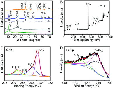
The XRD patterns of the original GO, RGO, Fe3O4 and NiAl LDH-based composites are shown in Fig. 1A. Obviously, the characteristic diffraction peaks of GO and Fe3O4 are clearly observed. The precursor GO shows an intensive characteristic (001) peak at 2θ = 11.4°, simultaneously, Fe3O4 has its characteristic peaks of (220), (311), (400), (422), (511) and (440).32,33 The diffraction peaks of (003), (006), (012) and (015) appearing in the pure NiAl LDH and NiAl LDH-based composites can be well indexed to the typical hexagonal face phase of standard NiAl hydrotalcite (JCPDS No. 15-0087), which demonstrates that the LDH crystal phase has been successfully formed.15,34 However, the characteristic diffraction peaks of GO and Fe3O4 in NiAl LDH-based composites are difficult to be observed in the XRD pattern, which could be attributed to the low loading content of Fe3O4. The results also illustrate that GO has been reduced to RGO via the hydrothermal process. It is noteworthy that there is no apparent main characteristic peak (002) at 2θ = 23.5° of graphene in the NiAl LDH-based composites.32 The reason for this phenomenon is that it may be shielded by the main peak (006) of NiAl LDH, suggesting that the strong interaction between NiAl LDH nanoplatelets and graphene effectively inhibits the restacking of the exfoliated graphene.15 Compared to the pure NiAl LDH, one is likely to find that the peak intensity of (003) in the NiAl LDH-based composites is weakened, which indicates that the crystallinity of LDH is decreased.1 Moreover, the boarding diffraction peaks strongly demonstrate that the addition of GO promotes the formation of smaller and thinner NiAl LDH platelets. In general, it can be concluded that graphene plays a critical role in the formation of LDH with smaller nanostructures.XPS was further conducted to investigate the surface chemical and valence states of the as-prepared nanocomposites. The wide scan XPS spectra of NiAl LDH/Fe3O4–RGO25 is shown in Fig. 1B. The photoelectron lines at binding energies of around 74, 284, 530, 711 and 856 eV are well indexed to Al 2p, C 1s, O 1s, Fe 2p and Ni 2p, respectively.35–38 In addition, the high resolution C 1s spectra shows four deconvolution peaks with binding energies of ca. 284.6, 286.3, 288 and 289.3 eV, demonstrating four types of C binding in the composite. The dominant peaks at ca. 284.6, 286.3 and 289.3 eV are characteristic of the non-oxygenated ring C (C![[double bond, length as m-dash]](https://www.rsc.org/images/entities/char_e001.gif) C/C–C), the carbon in C–O and the apparent oxygenated carbon species (O–C
C/C–C), the carbon in C–O and the apparent oxygenated carbon species (O–C![[double bond, length as m-dash]](https://www.rsc.org/images/entities/char_e001.gif) O), respectively.35,36 The weak peak at 288 eV (C
O), respectively.35,36 The weak peak at 288 eV (C![[double bond, length as m-dash]](https://www.rsc.org/images/entities/char_e001.gif) O) is due to the reduction of graphene via the hydrothermal process.37 The XPS spectrum also provides a path to verify the presence of magnetism, which is consistent with the XRD analysis. In the Fe 2p spectra (Fig. 1D), the peaks at 712.5 and 725.3 eV belong to Fe 2p2/3 and Fe 2p1/2, respectively.36,38 Notably, the satellite peak at 719 eV (γ-Fe2O3) strongly provides evidence for the formation of the Fe3O4 phase in the nanocomposite.38
O) is due to the reduction of graphene via the hydrothermal process.37 The XPS spectrum also provides a path to verify the presence of magnetism, which is consistent with the XRD analysis. In the Fe 2p spectra (Fig. 1D), the peaks at 712.5 and 725.3 eV belong to Fe 2p2/3 and Fe 2p1/2, respectively.36,38 Notably, the satellite peak at 719 eV (γ-Fe2O3) strongly provides evidence for the formation of the Fe3O4 phase in the nanocomposite.38
The chemical bond properties of the original GO, RGO and NiAl LDH-based composites were detected by FT-IR and micro-Raman spectroscopy, as can be seen in Fig. 2A and B.
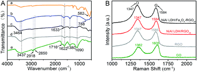 | ||
| Fig. 2 (A) FT-IR spectra of Fe3O4 (a), NiAl LDH (b), NiAl LDH/Fe3O4–RGO25 (c), RGO (d) and GO (e) and (B) Raman spectra of GO, RGO, NiAl LDH/RGO25 and NiAl LDH/Fe3O4–RGO25. | ||
The FT-IR spectra of the as-prepared samples in the range from 4000 to 500 cm−1 are shown in Fig. 2A. The peak at 582 cm−1 belongs to Fe–O and is caused by Fe3O4, similar to the previous researches.33,39 In the spectrum of GO, the relatively broad and strong absorption peaks at about 3437 cm−1 are associated with the hydroxyl stretching band (v O–H), which are arise from –COOH groups and water molecules.9 The absorption peaks at 2918 cm−1 and 2850 cm−1 are caused by the antisymmetrical and symmetrical vibrations of –CH2. The absorption peaks at 1716 cm−1 and 1622 cm−1 correspond to the stretching vibrations of C![[double bond, length as m-dash]](https://www.rsc.org/images/entities/char_e001.gif) O and C
O and C![[double bond, length as m-dash]](https://www.rsc.org/images/entities/char_e001.gif) C, respectively.9 In addition, the absorption peaks located at 1380 cm−1 and 1090 cm−1 are assigned to C–OH arising from the –COOH group and the C–O bending vibration.40,41 In the spectrum of NiAl LDH, the absorption peaks appeared at approximately 3464 cm−1 and 1633 cm−1, corresponding to the O–H stretching vibration caused by the interlayer water molecules and the H bond arising from the bending mode, respectively.15 Other absorption peaks below 800 cm−1 (such as 788 cm−1) are ascribed to the stretching and bending vibrations of metal–oxygen bonds (M–O) in the hydrotalcite.15 The spectrum of the NiAl LDH-based composites presents the same absorption peaks as that of pure NiAl LDH. However, characteristic absorption peaks of GO and Fe3O4 at 1716 cm−1 and 1090 cm−1 in NiAl LDH/Fe3O4–RGO25, respectively, are weaker in comparison with the pure samples. The FT-IR spectra further confirm the reduction of GO and the formation of NiAl LDH/Fe3O4–RGO25 composites, and are in agreement with the XRD and XPS analysis.
C, respectively.9 In addition, the absorption peaks located at 1380 cm−1 and 1090 cm−1 are assigned to C–OH arising from the –COOH group and the C–O bending vibration.40,41 In the spectrum of NiAl LDH, the absorption peaks appeared at approximately 3464 cm−1 and 1633 cm−1, corresponding to the O–H stretching vibration caused by the interlayer water molecules and the H bond arising from the bending mode, respectively.15 Other absorption peaks below 800 cm−1 (such as 788 cm−1) are ascribed to the stretching and bending vibrations of metal–oxygen bonds (M–O) in the hydrotalcite.15 The spectrum of the NiAl LDH-based composites presents the same absorption peaks as that of pure NiAl LDH. However, characteristic absorption peaks of GO and Fe3O4 at 1716 cm−1 and 1090 cm−1 in NiAl LDH/Fe3O4–RGO25, respectively, are weaker in comparison with the pure samples. The FT-IR spectra further confirm the reduction of GO and the formation of NiAl LDH/Fe3O4–RGO25 composites, and are in agreement with the XRD and XPS analysis.
As presented in Fig. 2B, all samples exhibit two intense Raman peaks for the D band and G band at about 1347 cm−1 and 1584 cm−1, respectively, which correspond to the defects and the in-plane vibration of the sp2 bond of the carbon atoms.42–44 It can be easily observed that the D band and G band of the NiAl LDH-based composites show a slight left-shift in comparison with the original GO. This confirms the significant reduction of GO during the hydrothermal process.16 Generally, the intensity ratio of the D and G bands (ID/IG) provides a method for evaluating the graphitization degree and defect density of the carbon species.42,45 The ID/IG values of NiAl LDH/Fe3O4–RGO25 and graphene are calculated to be 1.15 and 1.09, respectively, which are significantly greater than that of the original GO (ID/IG = 0.85). This indicates that the structure of the composite decorated with NiAl LDH nanoplatelets becomes more disordered. Moreover, the result further reveals the decrease in the average size of the in-plane sp2 domains during the reduction of the exfoliated graphene sheets.
The microstructure and morphology of NiAl LDH, NiAl LDH/RGO25 and NiAl LDH/Fe3O4–RGO25 were characterized by SEM and TEM. Fig. 3(a) shows the SEM image of NiAl LDH/Fe3O4–RGO25. Both the NiAl LDH crystals and the Fe3O4 nanoparticles appeared to be uniformly distributed on the surface of graphene layers with a bright colour and large curvature. Besides, some of the Fe3O4 nanoparticles are deposited on the NiAl LDH nanoplatelets. The detailed morphology was further detected by TEM. From the image in Fig. 3(b), it can be obviously identified that NiAl LDH consists of thin and transparent hexagonal platelets with a size of around 260 nm, and the thickness of the platelets is nearly 4–5 nm. In addition, the pure NiAl LDH sample shows two growth trends in the horizontal and vertical directions, accompanied by easy stacking between layers. Fig. 3(c and d) exhibit the TEM images of the NiAl LDH/RGO25 and NiAl LDH/Fe3O4–RGO25 composites, respectively. The Fe3O4 NPs are composed of spherical particles with a size of 15–20 nm, and the darker layers of LDH platelets are evenly dispersed on the surface of the wrinkled graphene with light-coloured lines vertically or horizontally and each component could be clearly distinguished. It should be pointed out that the size of the NiAl LDH in the composites is approximately 100–120 nm, which is smaller in comparison to the pure NiAl LDH. This is mainly attributed to the NiAl LDH generated and intercalated in the composite material reducing the aggregation of each component during the hydrothermal process.25,40 This result is in good agreement with the above discussion.
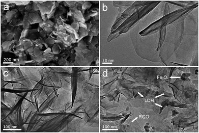 | ||
| Fig. 3 SEM image of NiAl LDH/Fe3O4–RGO25 (a) and TEM images of NiAl LDH (b), NiAl LDH/RGO25 (c) and NiAl LDH/Fe3O4–RGO25 (d). | ||
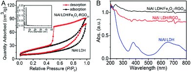
The specific surface area and pore size distribution of NiAl LDH and NiAl LDH/Fe3O4–RGO25 were measured by a N2 adsorption–desorption isotherm curve, as presented in Fig. 4A. Both isotherms exhibit a typical type-IV shape in the IUPAC classification with a classical H3-type (P/P0 > 0.4) hysteresis loop. This observation can be greatly regarded as evidence for NiAl LDH/Fe3O4–RGO25 possessing a slit-type mesoporous stacking structure of general 2D lamellar nanoplatelets.35,45,46 The specific surface area of NiAl LDH/Fe3O4–RGO25 is 93.76 m2 g−1, which is almost 2.7 times than that of NiAl LDH (34.91 m2 g−1). This is attributed to less aggregation between the graphene and NiAl LDH nanoplatelets through the incorporation of Fe3O4 NPs and graphene, and the intrinsic property of graphene.40 In general, a greater specific surface area could give rise to a smaller particle size, higher dispersion of active species and therefore superior catalytic performance.1,25 The pore size distribution of NiAl LDH/Fe3O4–RGO25 is around 5 nm. These results further demonstrate that both the greater specific surface area and the narrow distribution of pores would lead to more active sites for pollutant degradation and lower mass transfer resistance. This effectively improves the probability of collisions between the catalyst and the reactants, and therefore enhances the photocatalytic performance of the catalyst.
The optical absorption spectra of NiAl LDH and NiAl LDH-based composites were examined with UV-vis diffuse reflectance spectroscopy. As shown in Fig. 4B, in the case of NiAl LDH, there are two apparent absorption peaks located in the 350–400 nm and 650–700 nm regions, respectively.1 It is obviously observed that the spectra of the NiAl LDH-based composites are nearly straight lines in the range of 200–800 nm during incorporation with graphene and Fe3O4 NPs. Simultaneously, the spectra of the NiAl LDH/Fe3O4–RGO25 photocatalyst is more horizontal, which surely illustrates the synergistic effect of the metallic characteristic coupled with graphene.25 It can be found that the response to light of the NiAl LDH-based composites becomes more sensitive in both the UV and visible light regions, which results from not only the excellent light absorption capacity of graphene, but also the collective effect between graphene and NiAl LDH.
3.2 Study on the photocatalytic activity of NiAl LDH/Fe3O4–RGO25 composites
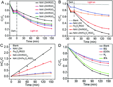
The photocatalytic performance of the as-prepared photocatalysts was evaluated via ciprofloxacin (CIP) photodegradation as the model reaction.47Fig. 5A shows the photocatalytic activities of the series of NiAl LDH/RGOx (x is the content of graphene) under visible light. The best photocatalytic effect is easily observed when the content of RGO is 25%. The essential reason for this phenomenon is the introduction of graphene into the system, which is beneficial to facilitating the separation of electron–hole pairs.22 However, as the ratio of graphene in the composite increased, the photocatalytic activity became weaker. This observation may be ascribed to extra graphene wrapping around the in situ growth of NiAl LDH, which hinders the exposure of active sites. Thus, we took 25 wt% of RGO in NiAl LDH/RGO as a proper ratio for further research.The corresponding concentration change of CIP and the reaction rate (k) as a function of absorption and irradiation time, respectively, for NiAl LDH, Fe3O4/RGO, NiAl LDH/RGO25 and NiAl LDH/Fe3O4–RGO25 samples as different photocatalytsts were monitored, as shown in Fig. 5(B and C). For the adsorption process in the dark, both NiAl LDH/RGO25 and NiAl LDH/Fe3O4–RGO25 exhibit an absorption capacity of nearly 30% for CIP, which is much higher than NiAl LDH (11%). This is probably due to the strong π–π interaction between graphene and the aromatic rings of CIP, and its greatly higher specific surface area, which has been discussed above in Fig. 4A. As can be seen, the direct photolysis of CIP in the absence of photocatalyst (2.43%) after visible light irradiation for 2.5 h could be ignored. It can be seen from Fig. 5B that the degradation efficiency of CIP follows the order: NiAl LDH/Fe3O4–RGO25 (91.36%) > NiAl LDH/RGO25 (70.35%) > NiAl LDH (27.37%) > Fe3O4/RGO (21.68%) after the same irradiation time. This clearly reveals that the photocatalytic activity of the composites has been well improved by hybridizing graphene and the Fe3O4 NPs.
As depicted in Fig. 5C, the photodegradation of organic contaminants is generally considered to satisfy a pseudo-first-order kinetic model when C0 is within the millimolar concentration range.48
| ln(C0/C) = kt |
The reaction rates of Fe3O4/RGO, NiAl LDH, NiAl LDH/RGO25 and NiAl LDH/Fe3O4–RGO25 came out from Fig. 5C to be 0.00183 min−1, 0.0087 min−1, 0.01579 min−1 and 0.0235 min−1, respectively. Notably, NiAl LDH/Fe3O4–RGO25 displays excellent photocatalytic performance and possesses the highest rate constant among all of the above samples, being 1.5 and even 3 times higher than that of NiAl LDH/RGO25 and pure NiAl LDH, respectively. This also further demonstrates that NiAl LDH/Fe3O4–RGO25 can serve as a promising photocatalyst to be applied in the degradation of antibiotics under visible light.
Furthermore, to investigate the active ingredients in the degradation of CIP using the NiAl LDH/Fe3O4–RGO25 photocatalyst, EDTA, benzoquinone (BQ) and isopropyl alcohol (IPA) were chosen as scavengers for a hole (h+), a superoxide radical (˙O2−) and a hydroxyl radical (˙OH), respectively.1 As shown in Fig. 5D, the results indicate that ˙O2− acts as the major oxidation species in the degradation of CIP, followed by h+. Meanwhile, it is observed that nearly 55% of CIP was degraded in the presence of N2, which is decreased in comparison with that under identical reaction conditions. It is attributed to the fact that an N2 purge is conducted to serve as ˙O2− radical scavengers to suppress the generation of ˙O2−.49 Therefore, we considered that the presence of O2 in the reaction vessel should have a significant influence on promoting photocatalytic activity.
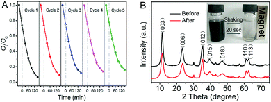
The favorable stability and reusability of a catalyst are also of vital importance in practical applications besides its catalytic activity. Therefore, we carried out five cycling tests to photodegrade CIP using the as-prepared photocatalyst. As shown in Fig. 6A, it is noteworthy that the photocatalytic activity of NiAl LDH/Fe3O4–RGO25 exhibits effective photostability under visible light irradiation. The photocatalytic efficiency decreases only 11.9% after five cycles, implying that the photocatalyst is stable. In the XRD pattern (Fig. 6B), there is no apparent change of the photocatalyst after the photocatalytic reaction, indicating that the NiAl LDH/Fe3O4–RGO25 composite has good stability. As Fig. 6B (inset) shows, the fast collection of the composite from the homogeneous dispersion within 20 seconds was clearly observed under an external magnetic field, while redispersion occurred immediately with a slight shaking when the magnetic field was removed. The result strongly indicates that NiAl LDH/Fe3O4–RGO25 shows considerable magnetic responsivity and redispersibility, which is significant in terms of its practical application.
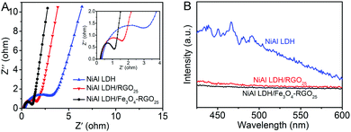
The electrical conductivity of the as-prepared photocatalysts were investigated utilizing EIS measurements, as shown in Fig. 7A. The inset picture is the magnified image of the high-frequency part. Compared with that of NiAl LDH, the impedance spectrum of NiAl LDH-based composites displayed a smaller radius. This indicates that the charge carrier transfer of NiAl LDH-based composites is greatly enhanced because of the superior electrical properties of graphene.1,50
In addition, the better separation efficiency of photogenerated electron–hole pairs in the NiAl LDH-based composites compared to pure NiAl LDH was demonstrated by PL spectra. The intensity of PL emission is related to the recombination rate of excited electron–hole pairs.51 It is generally believed that the higher intensity reveals the faster the recombination rate of excited electrons, and a lower intensity means more are transferred or trapped.52 As shown in Fig. 7B, NiAl LDH displays an emission peak at approximately 465 nm (λex = 340 nm), corresponding to the recombination of photogenerated charge carriers, whereas the NiAl LDH-based composites exhibited a much lower emission intensity than that of NiAl LDH. This indicates that the recombination of photogenerated electron–hole pairs was effectively inhibited in the NiAl LDH-based composites.53 The efficient charge separation also increased the lifetime of photogenerated charge carriers and improved the photocatalytic efficiency.
Based on the above analysis, a possible mechanism for the photocatalytic degradation process for NiAl LDH/Fe3O4–RGO25 was proposed. The electron transfer and the photocatalytic mechanism of NiAl LDH/Fe3O4–RGO25 are schematically illustrated in Fig. 8. Electrons (e−) in the valence band (VB) of NiAl LDH are swiftly excited to the conduction band (CB) with simultaneous formation of holes (h+) in the valence band once irradiated by visible light. According to previous literature, the work function of graphene and Fe3O4 and the conduction band (CB) of NiAl LDH are 4.42, 1.0 and −1.1 eV, respectively.3,54,55 Due to the CB of NiAl LDH being smaller than the work function of graphene, the photogenerated electrons in the CB of NiAl LDH would efficiently migrate into the unoccupied electron level of the graphene sheets, which are intimately and effectively decorated by NiAl LDH nanoplatelets.1,56 Besides, due to the high conductivity of Fe3O4, it can well serve as an acceptor of some of the photogenerated electrons from the CB of NiAl LDH.5,54 Here, in the NiAl LDH/Fe3O4–RGO composite system, the graphene acts as the electrical path for the photogenerated electrons from NiAl LDH, while Fe3O4 nanoparticles with superior electronic conductivity act as electron acceptors. Thus, these photogenerated electron–hole (e−–h+) pairs could be efficiently separated and the lifetime of the excited electrons and holes would be prolonged during the photocatalysis process. Subsequently, these transferred electrons from the graphene sheets and Fe3O4 nanoparticles both react with O2 adsorbed on the surface of the composite to generate ˙O2−, effectively inhibiting the recombination of electron–hole pairs, meanwhile, leaving holes to stay in the VB of NiAl LDH. Ultimately, these active components (˙O2− and h+) would oxidize the organic pollutant to form small inorganic molecules.
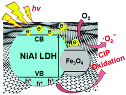 | ||
| Fig. 8 The schematic illustration of the photocatalytic reaction mechanism of the NiAl LDH/Fe3O4–RGO25 composite. | ||
4 Conclusions
In summary, the magnetically separable NiAl LDH/Fe3O4–RGO photocatalysts were successfully constructed through a facile hydrothermal method. The morphology of the samples revealed that directly in situ grown LDH nanoplatelets were provided with a smaller and thinner lamellar nanostructure, due to the addition of graphene as the support in comparison with the pristine NiAl LDH sample, and the Fe3O4 NPs also uniformly dispersed on the layers’ surface. The as-prepared composite materials are well dispersed in solution and could be easily separated by an external magnetic field. The presence of graphene and Fe3O4 nanoparticles significantly enhanced the specific surface area of the nanocomposites and provided more photo-active species. Compared with the pure NiAl LDH sample, graphene and Fe3O4 NPs both played critical roles in inhibiting charge recombination, and enhancing the light absorption of the NiAl LDH-based composites. The as-prepared NiAl LDH/Fe3O4–RGO25 composite displayed enhanced photocatalytic activity for antibiotic ciprofloxacin (CIP) degradation, and the degradation rate was 1.5 and even 3 times higher than that of NiAl LDH/RGO25 and pure NiAl LDH, respectively. Therefore, NiAl LDH/Fe3O4–RGO composites could be applied as promising catalysts for the photodegradation of residual antibiotics from aqueous solution as a practical application.Conflicts of interest
There are no conflicts to declare.Acknowledgements
The financial support from the National Natural Science Foundation of China (No. 51472035, 51572036, 51506012), the Science and Technology Department of Jiangsu Province (BY2016029-12, BE2014089, BY2015027-18), the Science & Technology Bureau of Changzhou (CE20160001-2, CM20153006, CJ20179037), the Science and Technology Project of Changzhou University (ZMF17020042) and the PAPD of Jiangsu Higher Education Institutions is gratefully acknowledged.References
- M. Lan, G. L. Fan, L. Yang and F. Li, Ind. Eng. Chem. Res., 2014, 53, 12943–12952 CrossRef CAS.
- J. J. Xue, S. S. Ma, Y. M. Zhou, Z. W. Zhang and M. He, ACS Appl. Mater. Interfaces, 2015, 7, 9630–9637 CAS.
- J. J. Xue, S. S. Ma, Y. M. Zhou, Z. W. Zhang and P. Jiang, RSC Adv., 2015, 5, 18832–18840 RSC.
- S. Ye, L.-G. Qiu, Y.-P. Yuan, Y.-J. Zhu, J. Xia and J.-F. Zhu, J. Mater. Chem. A, 2013, 1, 3008–3015 CAS.
- S. Kumar, S. T. B. Kumar, A. Baruah and V. Shanker, J. Phys. Chem. C, 2013, 117, 26135–26143 CAS.
- T. S. Anirudhan, J. R. Deepa and A. S. Nair, J. Ind. Eng. Chem., 2017, 47, 415–430 CrossRef CAS.
- M. N. Pahalagedara, M. Samaraweera, S. Dharmarathna, C.-H. Kuo, L. R. Pahalagedara, J. A. Gascón and S. L. Suib, J. Phys. Chem. C, 2014, 118, 17801–17809 CAS.
- X. N. Yu, X. Gao, Z. Y. Lu, X. L. Liu, P. W. Huo, X. L. Liu, D. Wu and Y. S. Yan, RSC Adv., 2013, 3, 14807–14813 RSC.
- B. W. Hu, C. C. Huang, X. Li, G. D. Sheng, H. Li, X. M. Ren, J. Y. Ma, J. Wang and Y. Y. Huang, Chem. Eng. J., 2017, 313, 527–534 CrossRef CAS.
- X. Ge, C. D. Gu, Z. Y. Yin, X. L. Wang, J. P. Tu and J. Li, Nano Energy, 2016, 20, 185–193 CrossRef CAS.
- J. Li, N. Zhang and D. H. L. Ng, J. Mater. Chem. A, 2015, 3, 21106–21115 CAS.
- S. Iguchi, K. Teramura, S. Hosokawa and T. Tanaka, Phys. Chem. Chem. Phys., 2015, 17, 17995–18003 RSC.
- X. X. Guo, F. Z. Zhang, S. L. Xu, D. G. Evans and X. Duan, Chem. Commun., 2009, 6836–6838 RSC.
- X. X. Ruan, Y. H. Chen, H. Chen, G. R. Qian and R. L. Frost, Chem. Eng. J., 2016, 297, 295–303 CrossRef CAS.
- M. Y. Miao, J. T. Feng, Q. Jin, Y. F. He, Y. N. Liu, Y. Y. Du, N. Zhang and D. Q. Li, RSC Adv., 2015, 5, 36066–36074 RSC.
- D. H. Youn, Y. B. Park, J. Y. Kim, G. Magesh, Y. J. Jang and J. S. Lee, J. Power Sources, 2015, 294, 437–443 CrossRef CAS.
- Y. F. Zhao, P. Y. Chen, B. S. Zhang, D. S. Su, S. T. Zhang, L. Tian, J. Lu, Z. X. Li, X. Z. Cao, B. Y. Wang, M. Wei, D. G. Evans and X. Duan, Chem. – Eur. J., 2012, 18, 11949–11958 CrossRef CAS PubMed.
- G. Fan, F. Li, D. G. Evans and X. Duan, Chem. Soc. Rev., 2014, 43, 7040–7066 RSC.
- K. M. Parida and L. Mohapatra, Chem. Eng. J., 2012, 179, 131–139 CrossRef CAS.
- M. Daud, M. S. Kamal, F. Shehzad and M. A. Al-Harthi, Carbon, 2016, 104, 241–252 CrossRef CAS.
- X. Y. Mei, J. Y. Wang, R. Y. Yang, Q. H. Yan and Q. Wang, RSC Adv., 2015, 5, 78061–78070 RSC.
- S. S. Yang, P. X. Wu, M. Q. Chen, Z. J. Huang, W. Li, N. W. Zhu and Y. R. Ji, RSC Adv., 2016, 6, 26495–26504 RSC.
- H. Q. Chen, M. B. Müller, K. J. Gilmore, G. G. Wallace and D. Li, Adv. Mater., 2008, 20, 3557–3561 CrossRef CAS.
- J. H. Liu, Z. C. Wang, L. W. Liu and W. Chen, Phys. Chem. Chem. Phys., 2011, 13, 13216–13221 RSC.
- J. L. Gunjakar, I. Y. Kim, J. M. Lee, N.-S. Lee and S.-J. Hwang, Energy Environ. Sci., 2013, 6, 1008–1017 CAS.
- B. Li, Y. F. Zhao, S. T. Zhang, W. Gao and M. Wei, ACS Appl. Mater. Interfaces, 2013, 5, 10233–10239 CAS.
- C. T. Yavuz, J. T. Mayo, W. W. Yu, A. Prakash, J. C. Falkner, S. Yean, L. Cong, H. J. Shipley, A. Kan, M. Tomson, D. Natelson and V. L. Colvin, Science, 2006, 314, 964–967 CrossRef PubMed.
- T. Zhang, X. W. Zhang, J. W. Ng, H. Y. Yang, J. C. Liu and D. D. Sun, Chem. Commun., 2011, 47, 1890–1892 RSC.
- Y. S. Kang, S. Risbud, J. F. Rabolt and P. Stroeve, Chem. Mater., 1996, 8, 2209–2211 CrossRef CAS.
- L. Zhang, W.-F. Dong and H.-B. Sun, Nanoscale, 2013, 5, 7664–7684 RSC.
- W. S. Hummers Jr. and R. E. Offeman, J. Am. Chem. Soc., 1958, 80, 1339 CrossRef.
- G. Y. He, H. Q. Chen, J. W. Zhu, F. L. Bei, X. Q. Sun and X. Wang, J. Mater. Chem., 2011, 21, 14631–14638 RSC.
- T. Fan, D. K. Pan and H. Zhang, Ind. Eng. Chem. Res., 2011, 50, 9009–9018 CrossRef CAS.
- Y. Y. Sun, J. B. Zhou, W. Q. Cai, R. S. Zhao and J. P. Yuan, Appl. Surf. Sci., 2015, 349, 897–903 CrossRef CAS.
- T. R. Zhan, Y. M. Zhang, X. L. Liu, S. S. Lu and W. G. Hou, J. Power Sources, 2016, 333, 53–60 CrossRef CAS.
- F. R. Zhang, Y. W. Song, S. Song, R. J. Zhang and W. G. Hou, ACS Appl. Mater. Interfaces, 2015, 7, 7251–7263 CAS.
- T. Wen, X. L. Wu, X. L. Tan, X. K. Wang and A. W. Xu, ACS Appl. Mater. Interfaces, 2013, 5, 3304–3311 CAS.
- X.-L. Wu, L. Wang, C.-L. Chen, A.-W. Xu and X.-K. Wang, J. Mater. Chem., 2011, 21, 17353–17359 RSC.
- R. D. Waldron, Phys. Rev., 1955, 99, 1727–1735 CrossRef CAS.
- Q. L. Fang and B. L. Chen, J. Mater. Chem. A, 2014, 2, 8941–8951 CAS.
- T. N. Reddy, J. Manna and R. K. Rana, ACS Appl. Mater. Interfaces, 2015, 7, 19684–19690 CAS.
- J. F. Shen, B. Yan, M. Shi, H. W. Ma, N. Li and M. X. Ye, J. Mater. Chem., 2011, 21, 3415–3421 RSC.
- Z. Wang, X. Zhang, J. H. Wang, L. D. Zou, Z. T. Liu and Z. P. Hao, J. Colloid Interface Sci., 2013, 396, 251–257 CrossRef CAS PubMed.
- Y. S. Fu, J. W. Zhu, C. Hu, X. D. Wu and X. Wang, Nanoscale, 2014, 6, 12555–12564 RSC.
- T. T. Xu, J. J. Xue, X. L. Zhang, G. Y. He and H. Q. Chen, Appl. Surf. Sci., 2017, 402, 294–300 CrossRef CAS.
- J. T. Zhang, Z. G. Xiong and X. S. Zhao, J. Mater. Chem., 2011, 21, 3634–3640 RSC.
- P. W. Huo, Y. F. Tang, M. J. Zhou, J. Z. Li, Z. F. Ye, C. C. Ma, L. B. Yu and Y. S. Yan, J. Ind. Eng. Chem., 2016, 37, 340–346 CrossRef CAS.
- X. H. Wang, J.-G. Li, H. Kamiyama, Y. Moriyoshi and T. Ishigaki, J. Phys. Chem. B, 2006, 110, 6804–6809 CrossRef CAS PubMed.
- Q. Liu, Y. R. Guo, Z. H. Chen, Z. G. Zhang and X. M. Fang, Appl. Catal., B, 2016, 183, 231–241 CrossRef CAS.
- Y. Y. Zhong, Y. Q. Liao, A. M. Gao, J. N. Hao, D. Shu, Y. L. Huang, J. Zhong, C. He and R. H. Zeng, J. Alloys Compd., 2016, 669, 146–155 CrossRef CAS.
- S. S. Ma, J. J. Xue, Y. M. Zhou and Z. W. Zhang, RSC Adv., 2015, 5, 40000–40006 RSC.
- L. C. Sim, K. H. Leong, S. Ibrahim and P. Saravanan, J. Mater. Chem. A, 2014, 2, 5315–5322 CAS.
- S. S. Ma, J. J. Xue, Y. M. Zhou, Z. W. Zhang and X. Wu, CrystEngComm, 2014, 16, 4478–4484 RSC.
- G. C. Xi, B. Yue, J. Y. Cao and J. H. Ye, Chem. – Eur. J., 2011, 17, 5145–5154 CrossRef CAS PubMed.
- S.-M. Xu, T. Pan, Y.-B. Dou, H. Yan, S.-T. Zhang, F.-Y. Ning, W.-Y. Shi and M. Wei, J. Phys. Chem. C, 2015, 119, 18823–18834 CAS.
- G. Y. He, J. J. Ding, J. G. Zhang, Q. L. Hao and H. Q. Chen, Ind. Eng. Chem. Res., 2015, 54, 2862–2867 CrossRef CAS.
| This journal is © the Owner Societies 2018 |

