 Open Access Article
Creative Commons Attribution 3.0 Unported Licence
Novel synthetic routes of large-pore magnetic mesoporous nanocomposites (SBA-15/Fe3O4) as potential multifunctional theranostic nanodevices†
Z.
Vargas-Osorio
*a,
M. A.
González-Gómez
a,
Y.
Piñeiro
 a,
C.
Vázquez-Vázquez
 b,
C.
Rodríguez-Abreu
c,
M. A.
López-Quintela
 b and
J.
Rivas
 a
a
aDepartamento de Física Aplicada, Facultade de Física, Universidade de Santiago de Compostela, E-15782, Santiago de Compostela, Spain. E-mail: zulema.vargas@usc.es
bDepartamento de Química Física, Facultade de Química, Universidade de Santiago de Compostela, E-15782, Santiago de Compostela, Spain
cInstituto de Química Avanzada de Cataluña, Consejo Superior de Investigaciones Científicas (IQAC-CSIC) and CIBER de Bioingeniería, Biomateriales y Nanomedicina (CIBER-BBN), Jordi Girona 18-26, 08034 Barcelona, Spain
First published on 9th November 2017
Abstract
In this paper, novel magnetic silica nanocomposites were prepared by anchoring magnetite nanoparticles onto the outer surface of mesoporous SBA-15 silica; the magnetic nanoparticles were prepared by microemulsion and solvothermal methods, varying the synthesis conditions in order to control the final physicochemical, textural and magnetic properties. The morphology and mesostructure of the materials were characterized by X-ray diffraction (XRD), Fourier-Transform Infrared Spectroscopy (FTIR), N2 adsorption–desorption, and Transmission and Scanning Electron Microscopy (TEM and SEM). Magnetic silica nanocomposites feature a two-dimensional hexagonal arrangement constituted by a homogeneous pore channel system with diameters between 13 and 18 nm and a Brunauer–Emmett–Teller (BET) surface area higher than 260 m2 g−1. The different morphologies of the samples are given by the presence of diverse magnetic nanoparticle arrangements covalently linked onto the outer surface of the mesoporous silica rods. This confers on them a superparamagnetic behaviour with a magnetic response between 50–80 emu g−1, even though the weight percent of magnetite present in the samples does not exceed 21.7%. In addition, the magnetic nanocomposites exhibit magnetic hyperthermia with moderate Specific Absorption Rate (SAR) values.
Introduction
Diverse hybrid nanostructures based on mesoporous silica ceramics are studied nowadays in a wide range of fields,1–5 such as drug delivery systems with the improved bioavailability of poorly water-soluble drugs,6,7 diagnosis probes,8 efficient heterogeneous catalysts,9,10 or in shale gas production.11 These applications arise from particular material properties such as the presence of a stable 2D hexagonal mesoporous structure with homogenous pore channels, high surface areas, large pore volume, narrow pore size distribution,12–14 thick pore walls, superior hydrothermal stability,15 three-dimensional pore connectivity,16 good biocompatibility17–19 and a chemically versatile surface that allows for covalently linking the organosilane species with surface silanol groups.20,21 In addition, the mechanical and chemical stability of the materials makes them suitable for protecting drugs and especially sensitive biomolecules such as peptides, enzymes, growth factors, antibodies, genes, DNA, RNA, plasmids from degradation or loss of activity in physiological or other harsh environments.6,22–24Magnetic nanoparticles are another class of materials with a wide range of applications, including in catalysis, as magnetic fluids, and in MRI, data storage, environmental remediation and biomedicine.25,26 The functionality of magnetic nanoparticles largely depends on their stability under a range of different conditions;27,28 therefore, coating shells are usually designed.29–31
In this context, the development of combined magnetic mesoporous silica/Fe3O4 nanocomposites will entail a big advantage in the production of multifunctional nanodevices with superior textural and magnetic properties.32,33 Different synthetic methods have been reported,34–37 aiming at the simultaneous control and optimization of morphological, textural and magnetic responses.38,39 Particularly for biomedical applications,40 these nanoplatforms must be biocompatible, have a superior loading capacity of drugs or biological entities and superparamagnetic behaviour in a well-defined mesoporous matrix.34,35,41,42 These characteristics allow for the well-controlled magnetically targeted drug delivery of specific moieties which are pore-depending;41,43,44 and used for bone tissue engineering;45–47 cell labeling and fluorescence;48,49 enhanced MRI contrast50,51 and magnetic hyperthermia.52–55 Notably, the production of heat by means of the magnetic excitation of magnetic nanoparticles, offers a large set of biomedical procedures covering new cancer therapies, magnetic tissue engineering, controlled drug delivery or multimode imaging/hyperthermia applications.53,56
In our previous paper,47 we reported on hybrid magnetic nanocomposites prepared from the mesoporous silica material SBA-15 (SBA-15/Fe3O4@PAA and SBA-15/Fe3O4@PEI), where the polyacrylic acid and polyethyleneimine functionalized magnetite NPs were in situ synthesized in the presence of the mesoporous SBA-15 matrix, resulting in the formation of hybrid functional systems, but with a moderated magnetic response due to the low crystallinity of the magnetic nanoparticles. Similar results are reported in the literature for other magnetic nanocomposites.28,35,36 In addition, the formation of the nanoparticles occurs randomly, both inside and outside the mesoporous matrix, and the amount of magnetic nanoparticles should be increased (ca. 20 wt%) in order to have a sufficient magnetic response. In this paper, we present new methodologies to anchor magnetite nanoparticles onto the external SBA-15 surface. In this way, we were able to prepare magnetic mesoporous SBA-15 silica hybrid materials with improved performance, which simultaneously retain the high magnetic response and well-ordered hexagonal pore arrangement and pore volumes similar to the parent SBA-15 matrix. The physicochemical, structural and magnetic properties investigated of the so-prepared magnetic mesoporous silica hybrids confirm the preservation of the properties of the individual components.
Materials
Tetraethyl orthosilicate (98%), iron(III) chloride hexahydrate (97%), hydrochloric acid (37%), ferrocene (98%), cyclohexane (99.8%), Igepal CO-520 (polyoxyethylene (5) nonylphenylether, branched), acetone (CHROMASOLV, for HPLC, >99.9%), isooctane (C8H18, ≥99%,) and 2-propanol (≥99.5%) were obtained from Sigma-Aldrich; hydrogen peroxide (30%) from Panreac; iron(II) sulfate heptahydrate (99%), ortho phosphoric acid (85%) and ammonium hydroxide (28%) from Fluka analytical; ethanol (99.9%) and acetone (≥99%) were purchased from Scharlau; and oleic acid (extra pure) from Merck. Milli-Q (Millipore®) deionized water was used in all the experiments.Experimental section
The characteristics of the synthesized materials are summarized in Table 1.| Formula | Sample name | Characteristics | Synthesis method |
|---|---|---|---|
| a Magnetite nanoparticles attached to the external SBA-15 surface by an ultra-thin SiO2 layering. b Magnetite aggregates or multi core–shell structures covalently linked to the external SBA-15 surface (C = carbon shell functionalized with carboxyl groups). | |||
| Fe3O4@OA | OAM | Oleic acid-coated magnetic nanoparticles | Co-precipitation |
| SBA-15 | S15 | Ordered mesoporous silica | Soft template |
| SBA-15/Fe3O4@SiO2a | LMNC | Low magnetic content nanocomposites | Microemulsion |
| HMNC | High magnetic content nanocomposites | Microemulsion | |
| SBA-15/Fe3O4@Cb | MANC | Magnetic aggregates nanocomposites | Solvothermal |
| CSNC | Multicore–shell nanocomposites | Solvothermal | |
(1) Preparation of OAM
Magnetic nanoparticles (NPs) were obtained by coprecipitation, following Massart's method57 with some modifications. In a typical synthesis, FeCl3·6H2O (90 mmol) and FeSO4·7H2O (60 mmol) were dissolved in 200 mL of 0.01 M HCl aqueous solution and mechanically stirred. The mixture was heated up to 60 °C, then NH4OH (1500 mmol) and oleic acid (14.2 mmol) were added, and the reaction was carried out for 1 h. After that, the sample was transferred to a beaker and placed on a hot plate at 100 °C to allow for precipitation. The precipitate containing OAM was retained with a magnet and the supernatant was removed. The OAM were washed three times with deionized water. Finally, the OAM were redispersed in cyclohexane, the remaining water was completely removed from the organic phase by using a decantation funnel. The total solid content was determined by thermogravimetry (TGA): Wmag = 17.4% by weight.(2) Preparation of S15 matrix
Ordered mesoporous silica was used in the nanocomposite synthesis described below. The synthetic procedure has been previously reported,39 based on the Colilla method.58 A triblock copolymer Pluronic P123 (PEO20–PPO70–PEO20) was dissolved at 35 °C in a mixture of deionized water and HCl/H3PO4. TEOS was then added to obtain a final molar composition of 1.0SiO2/0.017P123/2.2H3PO4/3.4HCl/208H2O. The reaction was continued under magnetic stirring over 24 h, followed by an aging step at 100 °C for 24 h; the resulting gel was collected by filtration. Finally, the product was dried and subjected to different washing cycles with organic solvents to remove the remaining block copolymer.(3) Preparation of LMNC and HMNC nanocomposites
This procedure is based on the formation of silica-coated core–shell magnetic nanoparticles in water-in-oil microemulsion systems59 but we have included the SBA-15 matrix in order to favour the anchoring of the magnetic nanoparticles to the outer surface of the SBA-15 matrix. For the synthesis of the nanocomposites, a 7.6 wt% solution of Igepal CO-520 in cyclohexane (555 mmol) was kept under mechanical stirring for 15 minutes, followed by the addition of oleic acid-coated magnetite nanoparticles (OAM, 4.8 mL). For the composite with low magnetic content (LMNC) a 5-fold diluted sample was prepared from the original OAM dispersion. After 30 minutes, NH4OH (25 mmol) and SBA-15 mesoporous silica (S15, 1 g) were incorporated into the mixture, which was stirred for 20 minutes prior to the addition of TEOS. Finally, the reaction was continued at room temperature for 16 h, under mechanical stirring and in the dark. After the reaction was completed, isopropyl alcohol (IPA) was added to precipitate the material; the supernatant was separated from the magnetic solid with the help of a magnet. The sample was further washed several times with ethanol (4×) and deionized H2O (5×). Finally, the sample was filtered and dried at 60 °C for 24 h.(4) Preparation of MANC and CSNC nanocomposites
Multicore magnetic mesoporous nanocomposites were prepared by adding mesoporous silica to the solvothermal preparation of multicore magnetic aggregates described by Wang et al.60 In a typical synthesis, ferrocene (1.3 mmol) was dissolved in acetone (272.4 mmol) under vigorous magnetic stirring for 30 min. Then, hydrogen peroxide was slowly added into the mixture and stirred for another 30 min. Later, the above solution was transferred to a 45 mL Teflon lined stainless steel autoclave that contained the SBA-15 sample (0.5 g for MANC and 0.25 g for CSNC nanocomposites). The container was closed and heated at 210 °C for 72 h. After that, the autoclave was allowed to cool down to room temperature. The obtained products were magnetically separated and washed with acetone three times. Finally, the products were filtered, washed with water and dried at 60 °C for 12 h.Instrumentation
The characterization of the crystalline phases of the materials was performed by X-ray diffraction (XRD) on powder samples with a Philips PW1710 diffractometer (Cu Kα radiation source, λ = 1.54186 Å). Measurements were collected in the 2θ angle range between 10° and 80° with steps of 0.02° and 10 s per step. The mesoporous matrix structure was analysed by low-angle XRD in a PANalytical X'Pert Powder Empyrean, in a 2θ range between 0.25 and 6°, and a step size of 0.01° (5 s per step). Pore size distribution and specific surface area were estimated from N2 adsorption–desorption isotherms obtained using a Quantachrome Autosorb IQ2 instrument. Morphology of the materials was characterized by scanning electron microscopy (SEM) using a Zeiss FE-SEM ULTRA Plus (5 kV) microscope. Transmission electron microscopy (TEM) images were obtained using a JEOL JEM-1011 microscope (100 kV). Magnetization curves as a function of the applied magnetic field up to 10 kOe were obtained at room temperature with a DMS 1660 vibrating sample magnetometer (VSM) on dried samples. Iron content in the nanocomposite samples was determined by flame atomic absorption spectroscopy (FAAS) in a Perkin Elmer 3110 Atomic Absorption Spectrometer. Fourier transform infrared (FTIR) spectra were recorded in a Thermo Nicolet Nexus spectrometer using the attenuated total reflectance (ATR) method.Magnetic hyperthermia experiments were performed by means of a homemade magnetic radio-frequency (RF) power generator operating at a fixed frequency of 293 kHz and an induced magnetic field of 30 mT. A cylindrical Teflon sample holder was placed at the midpoint of an ethyleneglycol cooled hollow coil (maximum of RF magnetic field), inside a thermally isolated cylindrical Dewar glass under high vacuum conditions (10−6 mbar). Measurements were carried out by placing powder samples in the sample holder and recording the temperature increase versus time with a fibre-optic thermometer (Neoptix) over ∼5 min of applied magnetic field.
Fig. 1a–d shows aspects of nanocomposite samples with different types and amounts of magnetite NPs. Fig. 1e confirms the good magnetic response of the nanocomposites.
 | ||
| Fig. 1 Aspect of nanocomposite samples (a) SBA-15/Fe3O4@C; (b and c) SBA-15/Fe3O4@SiO2 high and low magnetic content, respectively, (d) SBA-15, and (e) magnetic response of the LMNC sample. | ||
Results and discussion
X-ray diffraction
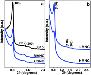
LMNC, MANC and CSNC nanocomposites possess a highly ordered 2D hexagonal structure (space group P6m),2,3,15,20,58 the same as their precursor SBA-15 matrices. XRD data show three well-resolved Bragg diffraction peaks corresponding to the (1 0 0), (1 1 0) and (2 0 0) planes (Fig. 2a and b). The HMNC material shows only the (1 0 0) reflection that can be attributed to a partial disruption of the structure at a high magnetite content or a decrease in the size of the mesoscale crystalline domains. The unit cell parameters (a0) calculated from the position of the (1 0 0) reflection are shown in Table 2.| Sample | 2θ (°) | d 100 (nm) | a 0 (nm) | 2θ (°) | d 311 (Å) | a 0 (Å) |
|---|---|---|---|---|---|---|
| SBA-15 | Fe3O4 | |||||
| S15 | 0.82 | 10.77 | 12.43 | — | — | — |
| LMNC | 0.84 | 10.50 | 12.13 | 35.68 | 2.52 | 8.34 |
| HMNC | 0.84 | 10.50 | 12.13 | 35.68 | 2.52 | 8.34 |
| MANC | 0.83 | 10.63 | 12.28 | 35.56 | 2.53 | 8.37 |
| CSNC | 0.83 | 10.63 | 12.28 | 35.56 | 2.53 | 8.37 |
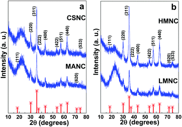
Powder XRD patterns of a wider-angle range of different magnetic SBA-15/Fe3O4 nanocomposites are presented in Fig. 3a and b. The position and relative intensities of the main peaks indicate that the main iron oxide phase present in the samples correspond to magnetite with an inverse spinel structure (JCPDS card No. 19-0629), although the presence of a minor contribution of other iron oxides cannot be ruled out. The broad band at 2θ = 20–25° is related to the short-distance disordered structure of the silica matrix. Cubic lattice parameters (a0) were calculated from the (311) reflections and are presented in Table 2. The results obtained for a0 are similar to the value reported for magnetite (8.396 Å, JCPDS card No. 19-0629).
FT-IR spectroscopy
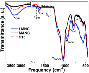
FT-IR spectra of magnetic nanocomposite materials and the SBA-15 precursor are shown in Fig. 4 (for LMNC and MANC nanocomposites) and S1 (for HMNC and CSNC nanocomposites). The analysis of the FT-IR spectrum of the MANC nanocomposite indicates that the anchoring of the magnetic nanoparticles takes place by the interaction between the silanol groups present on the surface of SBA-15 and the carbonyl-functionalized carbon shell of the multi core–shell structure, or by direct interaction with the surface atoms of magnetite, inasmuch as the SBA-15 spectrum presents the corresponding band of the silanol groups (at 951 cm−1) which disappears in the MANC and CSNC nanocomposites. However, it should be noted that LMNC and HMNC materials show a quite similar FT-IR spectrum as the corresponding SBA-15 precursor matrices.The characteristic bands of a pure-silica material are clearly observed, and the presence of a broad band between 3000–3700 cm−1 corresponds to the O–H stretching mode of silanol groups (νSiO–H). In addition, the high-intensity typical vibration band of SiO2 matrices was observed at 1040 cm−1 due to the presence of siloxane groups corresponding to the asymmetric stretching (νSi–O). Another characteristic weak band appeared at 790 cm−1, related to the symmetric stretching of Si–O (νSi–O). The free silanol groups discussed above are represented by the peak at 951 cm−1 (νSi–OH). Likewise, the stretching band (νC![[double bond, length as m-dash]](https://www.rsc.org/images/entities/char_e001.gif) O), located at 1702 cm−1, is attributed to the carbonyl functionalization of the carbon shell. The vibration bands observed at approximately 2900–3000 cm−1 correspond to the stretching (νC–H) and bending (δCH2) modes of aliphatic chains, and those at 1350–1480 cm−1 are characteristic of the C–H bond of the carboxylic acid. Finally, a weak vibration at ca. 1630 cm−1 can be assigned to the adsorption of water in the material surface given by δHOH.
O), located at 1702 cm−1, is attributed to the carbonyl functionalization of the carbon shell. The vibration bands observed at approximately 2900–3000 cm−1 correspond to the stretching (νC–H) and bending (δCH2) modes of aliphatic chains, and those at 1350–1480 cm−1 are characteristic of the C–H bond of the carboxylic acid. Finally, a weak vibration at ca. 1630 cm−1 can be assigned to the adsorption of water in the material surface given by δHOH.
Surface area and pore size determination (BJH and BET analysis)
Fig. 5a compares the N2-sorption isotherms of the precursor SBA-15 matrix and the MANC and LMNC nanocomposites, which best represent the characteristics of all the samples. All isotherms are of type IV, characteristic of mesoporous materials. Accordingly, there is a hysteresis loop, associated with the capillary condensation in mesopores, which occurs at a different pressure than the pore evaporation. Thus, the presence of parallel adsorption and desorption branches suggests the existence of cylindrical mesopores (hysteresis cycle type H1).61 However, the magnetic nanocomposites present narrower hysteresis cycles than their precursor matrix. Thus, their adsorption and desorption branches are closer, which means that the filling and subsequent emptying of their pores follow a similar mechanism in both stages that is directly related to an increase in their pore diameters, where the LMNC material not only has the largest pore diameter but also the narrowest hysteresis cycle, as is confirmed in Fig. 5b. Similar results are obtained for the other nanocomposites (HMNC and CSNC) and reported in Fig. S2 (ESI†).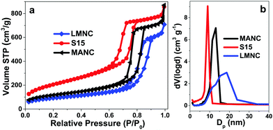 | ||
| Fig. 5 (a) Nitrogen adsorption–desorption isotherms and (b) pore size distribution of the S15 mesoporous matrix and the LMNC and MANC magnetic nanocomposites. | ||
The total pore volume was calculated on the basis of nitrogen adsorption data and the pore size distribution was estimated from the adsorption branch of the isotherms using the Barrett–Joyner–Halenda (BJH) method62 and the non-local density functional theory (NLDFT) method.63 Representative BJH pore size distributions are presented in Fig. 5b. It is evident that the pore size and the width of the distribution is larger in the composite materials as compared to the SBA-15 material. Even so, the MANC nanocomposite retains a relatively narrow pore size distribution, whereas in the LMNC sample, the distribution is wider. Similar results are obtained also by the NLDFT method but the pore sizes are slightly smaller (Table 3). This increase in the pore diameter could be associated with the formation and later interaction between polyoxyethylene (5) nonylphenyl ether (Igepal CO-520) micelles and the S15 material or by the presence of cyclohexane solvent in the microemulsion reaction.16 In addition, the presence of magnetic nanoparticles may result in textural porosity in the material coming from the interstitial voids between neighbouring nanoparticles, especially those adsorbed onto the surface of the silica particles, i.e. those that are not embedded in the mesoporous matrix (as can be observed in the TEM images of LMNC or MANC composites, Fig. 8 and 9). This interstitial porosity contributes with larger pore sizes and a higher polydispersity than those corresponding to the SBA-15 matrix.
| Sample | S BET (m2 g−1) | V p (cm3 g−1) | D BJH (nm) | D NLDFT (nm) | W mag (wt/wt%) |
|---|---|---|---|---|---|
| S BET is the surface area obtained by BET multipoint analysis, Vp is the total pore volume, DBJH and DNLDFT are the pore diameters obtained by BJH and NLDFT analysis, respectively. Wmag accounts for the magnetite content, Fe3O4, in the nanocomposites, obtained after the total iron content derived from FAAS. | |||||
| S15 | 727.07 | 1.219 | 8.986 | 8.145 | 0 |
| LMNC | 315.13 | 1.098 | 15.344 | 12.991 | 7.71 |
| HMNC | 261.96 | 0.914 | 18.534 | 14.997 | 21.70 |
| MANC | 405.64 | 1.127 | 13.078 | 10.885 | 10.99 |
| CSNC | 297.18 | 1.025 | 13.066 | 10.885 | 16.86 |
The specific surface areas (estimated by the multipoint BET method) are lower for the nanocomposites as compared to the SBA-15 material (see Table 3). This may suggest pore blocking by the embedded magnetic nanoparticles, which will result in less available surface area for gas adsorption. However, the relation between surface areas and magnetite weight percent shows two different behaviours that widely depend on the synthesis route. A linear behaviour is observed for those nanocomposites with aggregates and core–shell structures, which means that the increase in magnetite weight percent is directly proportional to the decrease in the surface area of the sample, as can be observed in Fig. 6. In contrast, for LMNC and HMNC materials, the behaviour is more similar to an exponential decay. Since these samples with different magnetic contents have a similar surface area (SBET), it appears that the lower SBET values of the composites relative to the native S15 material are attributed to the amorphous SiO2 coating used to anchor the magnetic nanoparticles. The results are summarized in Table 3.
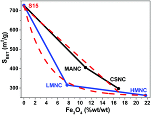 | ||
| Fig. 6 Relationship between the loss of specific surface area and magnetite weight percent present in samples according to the synthesis route. Dashed lines are a visual guide. | ||
Transmission and scanning electron microscopies (TEM, SEM)
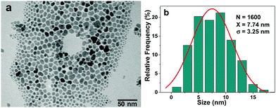
Fig. 7a shows a TEM micrograph of the precursor OAM used to prepare LMNC and HMNC nanocomposites. They present an irregular morphology with a relatively wide size distribution (Fig. 7b), with a maximum near 8 nm.SEM micrographs of the LMNC nanocomposite (Fig. 8) show the formation of the magnetite NPs layers anchored to the SBA-15 rods by means of an amorphous SiO2 unnoticeable coating. The presence of an ordered pore channel system is evidenced by means of a high-resolution TEM image (Fig. 8, centre-bottom), where both a regular mesoporous arrangement and the magnetite nanoparticles are observed. This innovative method allows obtaining a material with similar morphology to its SBA-15 precursor, but with the additional properties of the magnetic NPs.
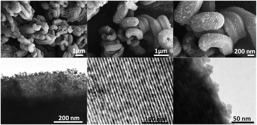 | ||
| Fig. 8 SEM (top) and TEM (bottom) micrographs at different magnifications and locations in the LMNC nanocomposite. | ||
The HMNC nanocomposite has a higher content of NPs onto the surface than that of the LMNC (Fig. 9), causing a padded appearance of the SBA-15 filaments; which means that the ordered pore arrangement is hidden by the large number of magnetite nanoparticles present in the HMNC nanocomposites. This behaviour has been corroborated by small angle XRD analysis by the disappearance of the minor peaks (110 and 200) due to the interference of the magnetite NPs distributed along the external surface.
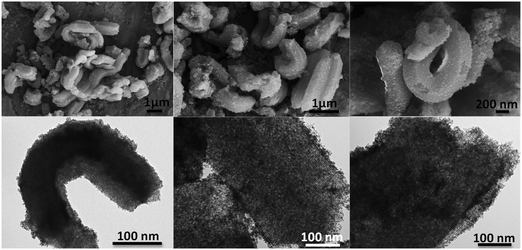 | ||
| Fig. 9 SEM (top) and TEM (bottom) micrographs at different magnifications and locations in the HMNC nanocomposite. | ||
The nanocomposites prepared by the solvothermal process (MANC and CSNC) present interesting and unique features. On one hand, the MANC material present irregular aggregates of about 50–150 nm formed by dozens of magnetite nanoparticles anchored to the outer surface of the mesoporous silica which makes them remarkably visible. This arrangement leaves free the inner surface of pores and also a high percentage of the outer surface (Fig. 10). This is the main reason why the three characteristic reflections of SBA-15 material are easily observed by XRD.
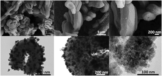 | ||
| Fig. 10 SEM (top) and TEM (bottom) micrographs at different magnifications and locations in the MANC nanocomposite. | ||
On the other hand, in the case of the CSNC sample (Fig. 11), the used reaction conditions led to the formation of multi core–shell structures (Fe3O4)n@C perfectly defined with diameters larger than 100 nm, similar to those reported by Wang et al. in the absence of the SBA-15.64 The magnetic core is mainly composed of multiple magnetite NPs between 8 and 16 nm of diameter. The clear difference between the MANC and CSNC nanocomposites is mainly related to the lower SBA-15 content in the CSNC nanocomposite.
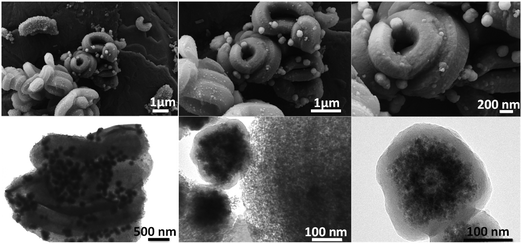 | ||
| Fig. 11 SEM (top) and TEM (bottom) micrographs at different magnifications and locations in the CSNC nanocomposite. | ||
Magnetic characterization of the materials
Magnetization curves versus applied magnetic field up to 10 kOe, were measured on dry samples at room temperature with a Vibrating Sample Magnetometer, VSM. Magnetization data were normalized to the amount of magnetite mass (Wmag) for each sample (determined by FAAS), assuming all the iron present in the sample exists as Fe3O4. The values for Wmag are summarized in the last column of Table 3. The magnetization curves in Fig. 12 show a nearly superparamagnetic behaviour (SPM) with negligible coercive fields (Hc < 30 Oe) and a slightly positive horizontal shift.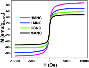 | ||
| Fig. 12 Hysteresis loops of SBA-15/Fe3O4@SiO2, SBA-15/Fe3O4@C magnetic mesoporous nanocomposites up to 10 kOe. | ||
The saturation magnetization values (between 50–80 emu g−1) of all the magnetic nanocomposites (MNCs) samples are below the bulk magnetite value for Mbulksat (92 emu g−1). This is consistent with a surface magnetic dead layer for small NPs (average crystallite size, Dhkl, is ca. 10 nm, as estimated from XRD using the Scherrer equation), that lowers the total magnetization. However, the initial magnetic susceptibility and the Msat of the present MNCs are larger than those of other similar mesoporous magnetic nanocomposites previously reported.35,36,41,65–70
There is a positive shift in the coercive field, observed in all the samples, that may be indicative of magnetostatic interactions in laterally confined structures,71 comprising dipolar or exchange interaction between nearby or touching magnetic NPs, respectively, or eventually exchange anisotropy.72 In addition, it can be observed that in those cases where the shift of the coercive field is large (LMNC and MANC) it also coincides with a lowering of the saturation magnetization.
Magnetic hyperthermia characterization
The magnetic hyperthermia results are shown in Fig. 13a. The most remarkable fact is that the thermal response can be tuned from negligible to a high heating rate, by a simple control of the chemical parameters, allowing for the design of different therapeutic approaches from mild hyperthermia to cell ablation, highly desirable in bone tissue engineering (e.g. drug delivery, tumour cell killing, etc.).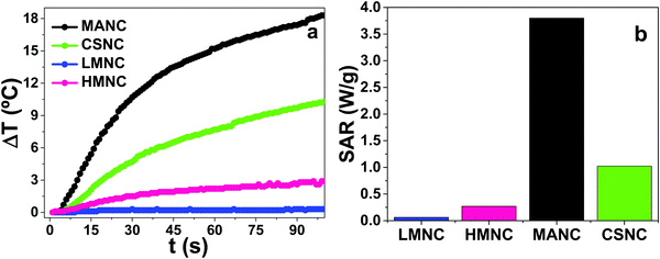 | ||
| Fig. 13 (a) Heating curves of LMNC, HMNC, MANC and CSNC nanocomposites and (b) specific absorption rate obtained from these heating curves. | ||
The magnetic hyperthermia study was carried out with solid powder samples, in order to mimic the actual situation of implanted solid bone scaffolds. The powder samples consisted of magnetite NPs firmly anchored to the outer surface of micrometric particles of mesoporous material. Therefore, under these conditions, only internal Néel magnetic relaxation can take place, since the physical rotation of the entire particle under the action of an alternating external magnetic field is not possible; the Brown relaxation contribution is then nil. In addition, mesoporous silica is an exceptional thermal insulator,3 due to its large porosity and strong phonon scattering. Thus, the large mesoporous silica matrices surrounding the magnetic particles hinder the heat diffusion through the mixture. Both facts underlie the mild thermal response of these MNCs.
In order to compare their heating efficiency, the specific absorption rate (SAR) for each sample was calculated (Table 4) using the following equation:
 , was calculated from the initial slope of the experimental curves (Fig. 13a), and the specific heat of mesoporous silica has been determined following the Machrafi approach for porous materials.73
| Sample | LMNC | HMNC | MANC | CSNC |
|---|---|---|---|---|
| (mgFe gNCs−1) | 55.8 ± 4.5 | 157.0 ± 1.0 | 79.5 ± 1.5 | 122.0 ± 3.0 |
| Characteristics of magnetic material attached to the outer SBA-15 surface | Low content of Fe3O4 NPs covered by SiO2 layer | High content of Fe3O4 NPs covered by SiO2 layer | Fe3O4 flowers | Well-defined core–shell structures |
| SAR (W g −1 ) | 0.06 | 0.27 | 3.80 | 1.01 |
The heating efficiency of the MNCs (Fig. 13b) shows two differentiated performances, low and high, depending on the morphology of the magnetic doping.
The first set of samples (LMNC and HMNC nanocomposites), with very low SAR, are composed by SBA-15 matrices with Fe3O4 NPs anchored on the outer surfaces and covered by a layer of SiO2 as depicted in Fig. 14. These set of samples show the lowest heating efficiency due to the confinement of Fe3O4 NPs between layers of super-insulating materials74 which hinder the heat diffusion to the surrounding medium.75 As a consequence, these magnetic nanocomposites could be applied as candidate agents for thermally-enhanced drug delivery,76 with the advantage of avoiding any external deleterious thermal activity77 during the application of external alternating magnetic fields.
 | ||
| Fig. 14 Semi core–shell structure of LMNC and HMNC NCs based on SBA-15/Fe3O4@SiO2. Magnetite NPs are surrounded by insulating material. | ||
The second set of MNCs with moderate SAR efficiency comprise MANC and CSNC samples, where magnetite aggregates or multicore magnetite NPs covered by a thick carbon shell (like those previously reported78) are anchored to the surface of SBA-15 matrices (see Fig. 10 and 11), respectively. The main differences in the heating efficiency can be attributed to the absence of a uniform carbon shell in MANC samples. The formation of a well-defined carbon shell in CSNC samples is behind their SAR differences.
Conclusions
We have successfully developed novel methods to prepare multifunctional nanodevices for several medical applications. The SBA-15 mesoporous silica matrix with an ordered pore structure, large surface area and high pore volume were the key to obtain different types of nanocomposites with a variety of properties. The physicochemical and structural characterization showed that the magnetic nanocomposites primarily maintain the morphology of SBA-15 materials with an ordered hexagonal distribution and high surface area, but induce the formation of larger pore diameters. The nanocomposites presented a superparamagnetic (SPM) response. The highest SPM response was observed in the HMNC nanocomposite due to a higher content of well-distributed magnetite NPs on the outer surface of the SBA-15 material. In general, all the materials presented interesting magnetic behaviour, showing higher magnetic responses than those of similar nanocomposites reported in the literature. Variable magnetic hyperthermia responses were obtained, which makes the materials suitable for different targets. Heating efficiency is restricted by the very low thermal conductivity of the silica present in both the mesoporous matrix and the SiO2 coating. Therefore, these magnetic nanocomposites are potential candidates for controlled drug delivery from the inside matrix without provoking an external deleterious thermal activity.Conflicts of interest
There are no conflicts to declare.Acknowledgements
This work was supported in part by MINECO (Spain) and FEDER Funds (projects MAT 2015-67458-P and CTQ2016-79461-R); and the European Commission (PANA project, Call H2020-NMP-2015-two-stage, Grant 686009; and the MADIA project, Call H2020-ICT-2016-1, Grant 732678).References
- M. Abdullahi, P. Panneerselvam, S. S. Imam and L. S. Ahmad, J. Pet. Technol. Altern. Fuels, 2016, 7, 31–37 CrossRef.
- I. Izquierdo-Barba, S. Sánchez-Salcedo, M. Colilla, M. J. Feito, C. Ramírez-Santillán, M. T. Portolés and M. Vallet-Regí, Acta Biomater., 2011, 7, 2977–2985 CrossRef CAS PubMed.
- C.-L. Huang, Y.-H. Feng, X.-X. Zhang, J. Li and G. Wang, Chin. Phys. B, 2013, 22, 64401 CrossRef.
- A. Danon, P. C. Stair and E. Weitz, J. Phys. Chem. C, 2011, 115, 11540–11549 CAS.
- Y. Cai, H. Li, B. Du, M. Yang, Y. Li, D. Wu, Y. Zhao, Y. Dai and Q. Wei, Biomaterials, 2011, 32, 2117–2123 CrossRef CAS PubMed.
- Z. Wang, B. Chen, G. Quan, F. Li, Q. Wu, L. Dian, Y. Dong, G. Li and C. Wu, Int. J. Nanomed., 2012, 7, 5807–5818 CAS.
- J.-T. Dai, Y. Zhang, H.-C. Li, Y.-H. Deng, A. A. Elzatahry, A. Alghamdi, D.-L. Fu, Y.-J. Jiang and D.-Y. Zhao, Chin. Chem. Lett., 2017, 28, 531–536 CrossRef CAS.
- Y. Jiang, S. Liu, Y. Zhang, H. Li, H. He, J. Dai, T. Jiang, W. Ji, D. Geng, A. A. Elzatahry, A. Alghamdi, D. Fu, Y. Deng and D. Zhao, Biomaterials, 2017, 115, 9–18 CrossRef CAS PubMed.
- M. Nandi, J. Mondal, K. Sarkar, Y. Yamauchi and A. Bhaumik, Chem. Commun., 2011, 47, 6677–6679 RSC.
- Z. Sun, J. Yang, J. Wang, W. Li, S. Kaliaguine, X. Hou, Y. Deng and D. Zhao, J. Mater. Chem. A, 2014, 2, 6071–6074 CAS.
- W. S. Chiang, E. Fratini, P. Baglioni, D. Georgi, J. H. Chen and Y. Liu, J. Phys. Chem. C, 2016, 120, 4354–4363 CAS.
- M. Vallet-Regí, M. Colilla and B. González, Chem. Soc. Rev., 2011, 40, 596–607 RSC.
- N. V. Reichhardt, T. Nylander, B. Klösgen, V. Alfredsson and V. Kocherbitov, Langmuir, 2011, 27, 13838–13846 CrossRef CAS PubMed.
- M. Vallet-Regí, Chem. – Eur. J., 2006, 12, 5934–5943 CrossRef PubMed.
- E. B. Celer, M. Kruk, Y. Zuzek and M. Jaroniec, J. Mater. Chem., 2006, 16, 2824 RSC.
- M. Kruk and L. Cao, Langmuir, 2007, 23, 7247–7254 CrossRef CAS PubMed.
- M. T. Al Samri, A. V. Biradar, A. R. Alsuwaidi, G. Balhaj, S. Al-Hammadi, S. Shehab, S. Al-Salam, S. Tariq, T. Pramathan, S. Benedict, T. Asefa and A.-K. Souid, Int. J. Nanomed., 2012, 7, 3111–3121 Search PubMed.
- M. Cicuéndez, I. Izquierdo-Barba, M. T. Portolés and M. Vallet-Regí, Eur. J. Pharm. Biopharm., 2013, 84, 115–124 CrossRef PubMed.
- T. Asefa and Z. Tao, Chem. Res. Toxicol., 2012, 25, 2265–2284 CrossRef CAS PubMed.
- A. Nieto, F. Balas, M. Colilla, M. Manzano and M. Vallet-Regí, Microporous Mesoporous Mater., 2008, 116, 4–13 CrossRef CAS.
- N. Lashgari, a Badiei and G. M. Ziarani, Nano Chem. Res., 2016, 1, 127–141 Search PubMed.
- Y. Zhao, X. Sun, G. Zhang, B. G. Trewyn, I. I. Slowing and V. S. Y. Lin, ACS Nano, 2011, 5, 1366–1375 CrossRef CAS PubMed.
- D. Molina-Manso, M. Manzano, J. C. Doadrio, G. Del Prado, A. Ortiz-Pérez, M. Vallet-Regí, E. Gómez-Barrena and J. Esteban, Int. J. Antimicrob. Agents, 2012, 40, 252–256 CrossRef CAS PubMed.
- J. M. Rosenholm, J. Zhang, W. Sun and H. Gu, Microporous Mesoporous Mater., 2011, 145, 14–20 CrossRef CAS.
- A. H. Lu, E. L. Salabas and F. Schüth, Angew. Chem., Int. Ed., 2007, 46, 1222–1244 CrossRef CAS PubMed.
- C. S. S. R. Kumar and F. Mohammad, Adv. Drug Delivery Rev., 2011, 63, 789–808 CrossRef CAS PubMed.
- S. P. Gubin, Y. a Koksharov, G. B. Khomutov and G. Y. Yurkov, Russ. Chem. Rev., 2005, 74, 489–520 CrossRef CAS.
- H. X. Jin, L. Li, N. J. Chu, Y. P. Liu, L. Y. Wang, Q. Lu, J. Qian, L. N. Sun, Q. Tang, H. L. Ge and X. Q. Wang, Mater. Chem. Phys., 2008, 112, 112–114 CrossRef CAS.
- L. Zhang, R. He and H. C. Gu, Appl. Surf. Sci., 2006, 253, 2611–2617 CrossRef CAS.
- E. D. Smolensky, H. Y. E. Park, T. S. Berquó and V. C. Pierre, Contrast Media Mol. Imaging, 2011, 6, 189–199 CAS.
- D. Dozier, S. Palchoudhury and Y. Bao, Joshua Faculty Sponsor, 2010, 7, 16–18 Search PubMed.
- M. Wang, X. Wang, Q. Yue, Y. Zhang, C. Wang, J. Chen, H. Cai, H. Lu, A. A. Elzatahry, D. Zhao and Y. Deng, Chem. Mater., 2014, 26, 3316–3321 CrossRef CAS.
- J. E. Lee, N. Lee, T. Kim, J. Kim and T. Hyeon, Acc. Chem. Res., 2011, 44, 893–902 CrossRef CAS PubMed.
- J. Liu, S. Z. Qiao, Q. H. Hu and G. Q. Lu, Small, 2011, 7, 425–443 CrossRef CAS PubMed.
- Y. Wang, J. Ren, X. Liu, Y. Wang, Y. Guo, Y. Guo and G. Lu, J. Colloid Interface Sci., 2008, 326, 158–165 CrossRef CAS PubMed.
- Y. Zhu, S. Kaskel, T. Ikoma and N. Hanagata, Microporous Mesoporous Mater., 2009, 123, 107–112 CrossRef CAS.
- A. De Sousa, K. C. De Souza, P. Maria, R. G. De Sousa, E. Martins and B. De Sousa, J. Nanomater., 2014, 2014, 1–10 CrossRef.
- S. H. Wu, C. Y. Mou and H. P. Lin, Chem. Soc. Rev., 2013, 42, 3862–3875 RSC.
- A. Acton, Advances in Nanotechnology Research and Application: Scholarly Editions, 2012, ch. 45, p. 1378 Search PubMed.
- N. Z. Knezevic, E. Ruiz-Hernández, W. E. Hennink and M. Vallet-Regí, RSC Adv., 2013, 3, 9584–9593 RSC.
- S. S. Huang, P. P. Yang, Z. Y. Cheng, C. X. Li, Y. Fan, D. Y. Kong and J. Lin, J. Phys. Chem. C, 2008, 112, 7130–7137 CAS.
- J. Zhang, X. Li, J. M. Rosenholm and H. C. Gu, J. Colloid Interface Sci., 2011, 361, 16–24 CrossRef CAS PubMed.
- P. Yang, S. Gai and J. Lin, Chem. Soc. Rev., 2012, 41, 3679–3698 RSC.
- K. C. Souza, J. D. Ardisson and E. M. B. Sousa, Study of mesoporous silica/magnetite systems in drug controlled release, J. Mater. Sci.: Mater. Med., 2009, 20, 507–512 CrossRef CAS PubMed.
- M. Bañobre-lópez, Y. Piñeiro-redondo, M. Sandri, A. Tampieri, R. De Santis, V. A. Dediu and J. Rivas, IEEE Trans. Magn., 2014, 50, 2327245 CrossRef.
- M. Vallet-Regí and E. Ruiz-Hernández, Adv. Mater., 2011, 23, 5177–5218 CrossRef PubMed.
- Z. Vargas-Osorio, Y. Piñeiro, C. Vázquez-Vázquez, C. Rodríguez-Abreu, M. A. Álvarez-Pérez, M. a. López-Quintela and J. Rivas, Int. J. Nanotechnol., 2016, 13, 648–658 CrossRef.
- Y.-S. Lin, C.-P. Tsai, H.-Y. Huang, C.-T. Kuo, Y. Hung, D.-M. Huang, Y.-C. Chen and C.-Y. Mou, Chem. Mater., 2005, 17, 4570–4573 CrossRef CAS.
- M. Zhao and C. Deng, Talanta, 2016, 159, 111–116 CrossRef CAS PubMed.
- H. Wu, G. Liu, S. Zhang, J. Shi, L. Zhang, Y. Chen, F. Chen and H. Chen, J. Mater. Chem., 2011, 21, 3037 RSC.
- S. Xuan, F. Wang, J. M. Y. Lai, K. W. Y. Sham, Y. J. Wang, S. Lee, J. C. Yu, C. H. K. Cheng and K. C. Leung, ACS Appl. Mater. Interfaces, 2011, 3, 237–244 CAS.
- X. Yu and Y. Zhu, Sci. Technol. Adv. Mater., 2016, 17, 229–238 CrossRef PubMed.
- Y. Piñeiro, Z. Vargas, J. Rivas and M. A. López-Quintela, Eur. J. Inorg. Chem., 2015, 4495–4509 CrossRef.
- C. Tao and Y. Zhu, Dalton Trans., 2014, 43, 15482–15490 RSC.
- F. M. Martín-Saavedra, E. Ruíz-Hernández, A. Boré, D. Arcos, M. Vallet-Regí and N. Vilaboa, Acta Biomater., 2010, 6, 4522–4531 CrossRef PubMed.
- A. Hervault and N. T. K. Thanh, Nanoscale, 2014, 6, 11553–11573 RSC.
- R. Massart, IEEE Trans. Magn., 1981, 17, 1247–1248 CrossRef.
- M. M. Colilla, F. Balas, M. Manzano and M. Vallet-Regí, Chem. Mater., 2007, 12, 3099–3101 CrossRef.
- A. B. Davila-Ibanez, V. Salgueiriño, V. Martinez-Zorzano, R. Mariño-Fernández, A. García-Lozano, M. Maceira-Campos, M. Múñoz-Ubeda, E. Junquera, E. Aicart, J. Rivas, F. J. Rodriguez-Berrocal and J. L. Legido, ACS Nano, 2012, 6, 747–759 CrossRef CAS PubMed.
- H. Wang, Q. W. Chen, Y. F. Yu, K. Cheng and Y. B. Sun, J. Phys. Chem. C, 2011, 115, 11427–11434 CAS.
- K. S. W. Sing, D. H. Everett, R. a. W. Haul, L. Moscou, R. a. Pierotti, J. Rouquérol and T. Siemieniewska, Pure Appl. Chem., 1984, 57, 2201–2218 Search PubMed.
- E. P. Barrett, L. G. Joyner and P. P. Halenda, J. Am. Chem. Soc., 1951, 73, 373–380 CrossRef CAS.
- P. I. Ravikovitch and A. V. Neimark, J. Phys. Chem. B, 2001, 105, 6817–6823 CrossRef CAS.
- H. Wang, Y.-B. Sun, Q.-W. Chen, Y.-F. Yu and K. Cheng, Dalton Trans., 2010, 39, 9565–9569 RSC.
- L. Yu, X. Yang and D. Wang, J. Colloid Interface Sci., 2015, 448, 525–532 CrossRef CAS PubMed.
- Y. Liu, R. Chen, D. Yuan, Z. Liu, M. Meng, Y. Wang, J. Han, X. Meng, F. Liu, Z. Hu, W. Guo, L. Ni and Y. Yan, Colloid Polym. Sci., 2014, 293, 109–123 Search PubMed.
- P. F. Wang, H. X. Jin, M. Chen, D. F. Jin, B. Hong, H. L. Ge, J. Gong, X. L. Peng, H. Yang, Z. Y. Liu and X. Q. Wang, J. Nanomater., 2012, 2012, 1–7 Search PubMed.
- H. Huang, Y. Ji, Z. Qiao, C. Zhao, J. He and H. Zhang, J. Autom. Methods Manage. Chem., 2010, 2010, 323509 CrossRef PubMed.
- L. P. Singh, S. K. Bhattacharyya, R. Kumar, G. Mishra, U. Sharma, G. Singh and S. Ahalawat, Adv. Colloid Interface Sci., 2014, 214, 17–37 CrossRef CAS PubMed.
- H. H. P. Yiu, M. a Keane, Z. a D. Lethbridge, M. R. Lees, A. J. El Haj and J. Dobson, Nanotechnology, 2008, 19, 255606 CrossRef CAS PubMed.
- D. Kechrakos and K. N. Trohidou, J. Nanosci. Nanotechnol., 2008, 8, 2929–2943 CrossRef CAS PubMed.
- A. E. Berkowitz and K. Takano, Exchange anisotropy – a review, J. Magn. Magn. Mater., 1999, 200(1), 552–570 CrossRef CAS.
- H. Machrafi and G. Lebon, Phys. Lett. Sect. A: Gen. At. Solid State Phys., 2015, 379, 968–973 CAS.
- Y. Belmoujahid, M. Bonne, Y. Scudeller, D. Schleich, Y. Grohens and B. Lebeau, Eur. Phys. J.: Spec. Top., 2015, 224, 1775–1785 CrossRef CAS.
- J. Rivas, M. Bañobre-López, Y. Piñeiro-Redondo, B. Rivas and M. A. López-Quintela, J. Magn. Magn. Mater., 2012, 324, 3499–3502 CrossRef CAS.
- X. Yua and Y. Zhub, Sci. Technol. Adv. Mater., 2016, 17, 229–238 CrossRef PubMed.
- A. A. Gupte, D. Shrivastava, M. A. Spaniol and A. Abosch, Stereotact. Funct. Neurosurg., 2011, 89, 131–140 CrossRef PubMed.
- Z. Vargas-Osorio, B. Argibay, Y. Piñeiro, C. Vázquez-Vázquez, M. A. López-Quintela, T. Sobrino, F. Campos, J. Castillo and J. Rivas, IEEE Trans. Magn., 2016, 52, 2300604 CrossRef.
Footnote |
| † Electronic supplementary information (ESI) available. See DOI: 10.1039/c7tb01963g |
| This journal is © The Royal Society of Chemistry 2017 |

