Facile synthesis of ultrathin Ni-MOF nanobelts for high-efficiency determination of glucose in human serum†
Xiao
Xiao
 ,
Shasha
Zheng
 ,
Xinran
Li
 ,
Guangxun
Zhang
 ,
Xiaotian
Guo
 ,
Huaiguo
Xue
and
Huan
Pang
 *
*
School of Chemistry and Chemical Engineering, Institute for Innovative Materials and Energy, Yangzhou University Yangzhou, Jiangsu 225002, China. E-mail: huanpangchem@hotmail.com; panghuan@yzu.edu.cn
First published on 8th June 2017
Abstract
Ultrathin Ni-MOF nanobelts, [Ni20(C5H6O4)20(H2O)8]·40H2O(Ni-MIL-77 NBs), were synthesized by a facile one-pot solution process and can be used as an efficient catalyst electrode for glucose oxidation under alkaline conditions. Electrochemical measurements demonstrate that the NB/GCE, when used as a non-enzymatic glucose sensor, offers superior analytical performances with a wide linear range (from 1 μM to 500 μM), a low detection limit (0.25 μM, signal-to-noise = 3), and a response sensitivity of 1.542 μA mM−1 cm−2. Moreover, it can also be applied for glucose detection in human blood serum with the relative standard deviation (RSD) of 7.41%, showing the high precision of the sensor in measuring real samples.
Introduction
Metal–organic frameworks, commonly called MOFs, are permanently microporous materials formed via auto-assemblage of metal ions and organic ligands in appropriate solvents.1 MOFs have crystalline structures and typically are characterized by large surface areas, uniform but adjustable cavities and adsorption affinities.2 Also, MOFs are a class of fast-growing porous material for sensing with outstanding features including well-defined channels and cavities of regular size and shape that are easily adjustable on the nanometer scale.3–7 As unique host matrices for multifarious functional species, MOFs can also be used to develop new-types of composites that display enhanced or new behaviours compared to the parent MOF counterparts, such as nanobelts,8,9 nanopores,10–12 nanoparticles13 and so forth. In particular, nanobelts of MOFs with a rectangular cross section in a ribbon-like morphology are very promising for electrochemical activity due to the fact that the surface-to-volume ratio is very high and they have a highly active surface.9 Moreover, nanobelts have a high electrocatalytic ability due to the marked resistance variation, which is characterized by fast response, high sensitivity and good selectivity.9 So MOFs with ultrathin nanobelt morphology have the potential to become an excellent electrode material.8Diabetes mellitus (DM) is a group of chronic diseases characterized by hyperglycemia,16 and early diagnosis of DM is the key to the successful management of the disease. For this reason, blood glucose levels should be determined using very sensitive and facile methods. An ideal non-enzymatic glucose (NEG) sensor should demonstrate a combination of properties, such as fast response, high sensitivity, good selectivity and stability.17 Over the past few decades, nickel-based metal–organic frameworks with diverse structures such as nanocubes,18 nanospheres,19 nanoparticle19etc. have been prepared and widely applied in adsorption,20 catalysis21 and supercapacitors.22 However, they have rarely been applied to construct NEG sensors.
Here, nickel-based metal–organic framework Ni-MIL-77 ultrathin nanobelts are successfully synthesized under solvothermal conditions in this work. Furthermore, the effects of the synthesis conditions (during the synthesis of the MOF, the solvothermal reaction time is changed as 48 h, 24 h and 12 h, respectively) on the growth of the nickel-based MOF have been explored. The obtained ultrathin Ni-MIL-77 nanobelts were immobilized on a glassy carbon electrode (GCE) by physical adsorption to determine the amount of GLU. The detection limit has been estimated to be 0.25 μM with a wide linear range from 1 μM to 500 μM. More importantly, Ni-MIL-77 ultrathin nanobelts are successfully primarily applied as a NEG sensor in human serum, and have a good selectivity, stability and detection limit and good sensitivity for the determination of glucose in human serum.
Results and discussion
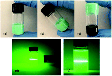
During our study, a self-supporting gel which endows the ultrathin nanobelts with great power for the encapsulation of functional molecules (Fig. 1a–c) was formed by common solvents.14,15,40 Furthermore, the Tyndall effect observed with a laser in Fig. 1d and e directly verified that the product is a gel system, which endows the synthesized hydrogels with a versatile platform for further applications. Hydrogels can be prepared using a covalent or a non-covalent approach. Most polymer hydrogels, covalently crosslinked, are brittle, have poor transparency and lack the ability to self-heal. But, the importance of the concepts “surface” and “porosity” associated with MOFs, together with their inherent stability, gives rise to an opportunity of properties and, hence, applications in the hydrogel system.47,48 In this work, although we did not conduct further studies in the field of hydrogels, we hope to provide reliable basic information on Ni-MIL-77 that will inspire other researchers and future research.The phase purity and crystallographic structure of the experimental product was tested by XRD. As shown in Fig. S1 (ESI,† the samples synthesized at reaction times of 48 h, 24 h and 12 h are referred to as K1, K2 and K3, respectively), and the higher the reaction time, the stronger the peak intensity and the narrower the peak width. This shows that the crystallinity becomes better as the solvothermal time increases and directly reflects that the three compounds are the same substance.
We have also measured the Fourier transform infrared (FT-IR) patterns of the MOFs (Fig. S2, ESI†). The strong and wide peak at 3364 cm−1 can be ascribed to the stretching mode of hydroxyl groups (O–H) that was coupled with Ni2+ as well as the peaks at 2932 cm−1, 1451 cm−1, and 1398 cm−1 (representative of C–H bonds). More importantly, the strong bands at 1605 cm−1 can be attributed to the characteristic mode of alkene (C![[double bond, length as m-dash]](https://www.rsc.org/images/entities/char_e001.gif) C). FT-IR indirectly confirms the formation of a MOF, and directly reflects that the three compounds are the same substance at the molecular level.
C). FT-IR indirectly confirms the formation of a MOF, and directly reflects that the three compounds are the same substance at the molecular level.
Fig. S3 (ESI†) gives the thermogravimetric (TG) curve of K1, which displays two clear weight changes. The first step of the weight change (6% decreased) takes place at the temperature range of 25–100 °C, corresponding to the loss of adsorbed solvent molecules. When the temperature rises to 400 °C there is a steep weight loss of 40.1%, ascribed to the decomposition of the MOF skeleton and the gasification of glutaric acid (HOOC(CH2)3COOH) ligands.
The electrochemical properties of the calcined products were tested in the subsequent experiments. The XRD pattern in Fig. S4 (ESI†) for P1 by calcining K1 at 400 °C for 2 h shows that two types of diffraction peaks (NiO and Ni) are obtained. Five well-defined diffraction peaks at 37.09°, 43.09°, 62.58°, 75.29°, and 79.31° are assigned to the (001), (200), (111), (021), and (002) facets of NiO, respectively. These diffraction peaks can be readily assigned to the standard NiO phase (JCPDS 65-5745) and Ni phase (JCPDS 65-2865).
The morphology of the samples is examined by field emission scanning electron microscopy (FESEM), transmission electron microscopy (TEM) and atomic force microscopy (AFM). A typical low-magnification SEM image in Fig. 2a and b shows that the morphology of K1 is ultrathin nanobelts. To gain further insight into the architecture of the Ni-MOF ultrathin nanobelts, TEM images (Fig. 2c) are obtained. The energy-dispersive X-ray spectrum (EDX)-mapping shows the reasonable elemental constituents (e.g., Ni, C and O) of the product with no other impurities in the NBs (Fig. 2e–h). AFM measurement is further used to confirm the thickness of a single nanobelt, as shown in Fig. 2d. It can be seen that the thickness is ∼4 nm in the inset of Fig. 2d.
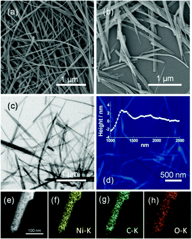 | ||
| Fig. 2 FESEM images (a and b); TEM image (c); corresponding AFM image (d); EDX elemental mapping images of Ni, C and O for K1 (e–h). | ||
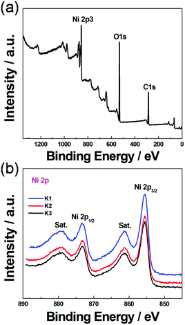
X-ray photoelectron spectroscopy (XPS) is an effective method to distinguish the elemental type and composition of functional groups in the products. The typical XPS of K1 as well as its survey spectra are exhibited in Fig. 3, in which the survey spectra (Fig. 3a) exhibit three obvious peaks at 282.63 (C 1s), 530.29 (O 1s) and 856.37 (Ni 2p3), respectively, which suggested that Ni-MIL-77 nanobelts were successfully formed. Four different peaks are observed in the high-resolution Ni 2p spectra (Fig. 3b). According to the previous literature reports,23,24 two major peaks centred at ca. 855.9 and 873.5 eV can be ascribed to Ni 2p1/2 and Ni 2p3/2, respectively. In addition, the broad peaks located at 861.1 eV and 879.6 eV are the satellite peaks of Ni 2p1/2 and Ni 2p3/2. Furthermore, a spin-energy separation of 17.6 eV can be calculated from the major peaks of Ni 2p1/2 and Ni 2p3/2. These results concluded from the Ni 2p spectra prove that nickel ions exist as Ni2+ in the as-prepared Ni-based MOFs.
When the hydrothermal reaction time is shortened to 24 h and 12 h (the reaction temperature is still 180 °C), a mixed and disordered morphology (Fig. S5a and b, ESI†) is obtained. We also verify the influence of calcination temperature on the morphology and properties of the samples (Fig. S5c, ESI†). The structure of [Ni20(C5H6O4)20(H2O)8]·40H2O is broken severely during the calcination procedure (400 °C), proving that appropriate experimental conditions are indispensable in keeping the composition and shapes of the experimental results.
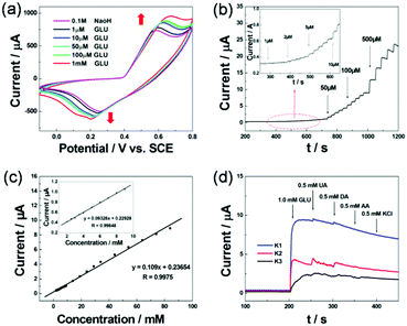
Different structures might lead to diverse electrochemical conditions for ions intercalated/extracted in/out and electrolyte access. Before the formal experiment, we tested the optimal voltage range and scanning rate of this experiment. As shown in Fig. S6a (ESI†), the NB/GC electrode showed a stronger current between −0.1 and 0.8 V. From Fig. S6b (ESI†), we can conclude that the scanning rate of 0.1 V s−1 is the most appropriate. When the scanning rate is too fast, the surface of the electrode is less than the occurrence of redox reactions; however, when the scanning rate is too slow, it will delay the occurrence of the reaction. The pH of the solution also has a great impact on the experimental results. As shown in Fig. S7 (ESI†), we evaluated the sensor activity of the NB/GC electrode toward the reduction of GLU in 0.1 M PBS (PH = 7.4) with the protection of N2. Compared with Fig. 5a, it is obvious that K1 exhibits superior electrochemical performance under alkaline conditions.
In the formal experiment, we evaluated the sensor activity of the Ni-MIL-77 nanobelt modified GCE electrode toward the reduction of GLU in 0.1 M NaOH (pH = 13.02, in this article 0.1 M NaOH solution all for this pH) with the protection of N2. The electocatalytic activity of the NB/GC electrode (K1 ultrathin nanobelt modified electrode) in the presence and absence of GLU is shown in Fig. 5a. Without glucose, the anodic peak current increased distinctly at about 0.58 V during successive scans. When 1.0 mM glucose is added into the NaOH solution (0.1 M), there is a great enhancement of the anodic peak current. This is attributed to the catalytic effect of the Ni3+ for the oxidation of GLU to glucolactone according to the following reactions (Fig. 4):
| Ni(II)-MOF → Ni(III)-MOF + e− |
| Ni(III)-MOF + OH− + Glucose → Ni(II)-MOF + Glucolactone + H2O + e− |
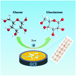 | ||
| Fig. 4 Schematic illustration of the MOF modified GCE used for the detection of GLU in 0.1 M NaOH solution. | ||
To confirm the linear working range of the NB/GC electrode, the amperometric response is recorded as a function of glucose concentration. Fig. 5b displays the typical current–time curves at +0.6 V of the K1 ultrathin nanobelt modified electrode with the successive injection of GLU solution with concentrations from 1 μM to 500 μM. An obvious response appears when the GLU solution concentration is even as low as 1 μM. It can be seen from the inset of Fig. 5b that NB/GCE modified with K1 displays a sensitive increase in current response after successive increments of GLU in 0.1 M NaOH with the protection of N2. The current responses increase sensitively and rapidly after each increment of GLU, which indicates a good linear dependence. As presented in Fig. 5c, two linear working ranges are obtained. More importantly, from the plots of electrocatalytic current versus GLU concentration in the range of 2–100 mM (Fig. 5c), the simulated linear equation of the M1 modified GCE is found to be: I (μA) = 0.23654 + 0.109Cglucose (mM), R = 0.9814, and the calculated sensitivity is 1.5420 μA mM−1 cm−2. The inset in Fig. 5c exhibits a good linear response in the range from 2.0 mM to 10.0 mM GLU with a relation coefficient of 0.99848.
The capability of distinguishing the target molecule from the interferents normally present in a complex biological environment is extremely important for a sensor. Thus, we further investigate the influence of some electroactive species on the response of the NB/GC electrode. The amperometric response of the modified electrode was tested by adding uric acid (UA), dopamine hydrochloride (DA), ascorbic acid (AA) and KCl. Fig. 5d shows the amperometric response of the sensor to the consecutive addition of glucose (1.0 mM), UA (0.5 mM), DA (0.5 mM), AA (0.5 mM) and KCl (0.5 mM) to the solution. The current response of 1.0 mM glucose is remarkable. By successively adding 0.5 mM of DA and UA, there is only a relatively small increase in current response and no current response to 0.5 mM AA and KCl. These results indicate that the ultrathin nanobelt modified GCE can be used for the sensitive and selective detection of GLU with negligible interference from KCl, DA, AA and UA.
The electrochemical experiments were carried out in the protection of N2. The existence of oxygen in the solution has some effects on the experimental results; the greater the oxygen concentration, the more obvious the redox peak (shown Fig. S8b and c, ESI†).
To investigate the morphology of the examined structures, several electrochemical analysis methods were performed on each nickel-based product. K2, K3 and P1 were also used to modify the GCE, and their electrocatalytical properties toward the reduction of GLU were studied and compared with those of K1. Fig. S9a–d (ESI†) displays their electrocatalytic properties. Fig. S6d (ESI†) displays the amperometric responses of P1. A comparison of the typical cyclic votammogram curves and current–time curves under the same conditions revealed a clear trend that the current responses increased with an increase in the excellent morphology. In the first, the MOF-based GLU sensor is clearly a promising candidate because MOFs can exhibit excellent structural diversity, tailorability and extraordinary adsorption affinities.25 Furthermore, nanobelts are as thin as 3–5 nm, so almost the entire thickness is affected by the redox reactions with the surface structure. This suggested that the catalytic activity of the nickel-based electrode materials was associated with its higher surface area and channels for ion diffusion.9,25
In order to further appraise the properties of the NB/GCE, a correlative reference of the sensor with other typical noble metal based NEG sensors reported recently is shown in Table 1. It can be clearly seen that the as-prepared NB/GCE possesses a good superiority not only in terms of detection limit and linear range, but also sensitivity for glucose determination.
| Electrode materials | Linear range (μM) | Detection limit (μM) | Sensitivity (μA mM−1 cm−2) | Ref. |
|---|---|---|---|---|
| AuNPs/PPy/RGO | 200–1200 | Not reported | 123.8 | 26 |
| AuNTs–Cu2O | 100–5000 | 1.83 | 1215.7 | 27 |
| Au–CeO2 | 10–1000 | 10 | 57.5 | 28 |
| AuNPs–Fe3O4 | 3–570 | 1.2 | Not reported | 29 |
| PtNDs–ZnONRs | 1000–18![[thin space (1/6-em)]](https://www.rsc.org/images/entities/char_2009.gif) 000 000 |
1560 | 82.76 | 30 |
| PtNC–CNT | 0.2–12![[thin space (1/6-em)]](https://www.rsc.org/images/entities/char_2009.gif) 000 000 |
0.2 | 280 | 31 |
| Fe@Au | 2400–54![[thin space (1/6-em)]](https://www.rsc.org/images/entities/char_2009.gif) 000 000 |
510 | 0.806 | 32 |
| NPG/CuO | 1000–12![[thin space (1/6-em)]](https://www.rsc.org/images/entities/char_2009.gif) 000 000 |
2.8 | 374.0 | 33 |
| Ag2O nanowalls | 200–3200 | 10 | 4218.6 | 34 |
| PdNPs/GO | 200–10![[thin space (1/6-em)]](https://www.rsc.org/images/entities/char_2009.gif) 000 000 |
Not reported | Not reported | 35 |
| Pt/CuONFs | 0.2–2500 | 190 | 1061.4 | 36 |
| RuOx–RuCN | 300–2000 | 40 | 6.2 | 37 |
| RuO | 0–4000 | 21 | 40.2 | 38 |
| MWCNT–RuO2 | 500–50![[thin space (1/6-em)]](https://www.rsc.org/images/entities/char_2009.gif) 000 000 |
33 | Not reported | 39 |
| Ni-MIL-77 | 1–500 | 0.25 | 1.542 | This work |
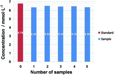
Real samples were tested to evaluate the practicability of this sensor. In order to appraise the actual level of the as-prepared NB/GCE in human serum, a serum sample with a glucose concentration of 6.79 mM was tested five times. Fig. 6 shows the bar graph of the response currents towards the six measurements. The results range from 6.35 to 6.52 mM. The average value is 6.43 mM, which is 5.3% lower than 6.79 mM, indicating a system error between the two test methods. Furthermore, the relative standard deviation (RSD) is 7.41%, showing high precision of the sensor in measuring real samples.
Experimental section
Preparation of Ni-MOF
C5H8O4 (HOOC(CH2)3COOH, 0.3960 g), Ni(CH3COO)2·4H2O (0.4940 g), and KOH (0.2300 g) are dissolved in a mixture solution (20 mL) containing 1![[thin space (1/6-em)]](https://www.rsc.org/images/entities/char_2009.gif) :
:![[thin space (1/6-em)]](https://www.rsc.org/images/entities/char_2009.gif) 1 ethanol and deionized water. The mixture was then dispersed in a NaOH (2 mL, 0.4 M) aqueous solution under stirring. Subsequently, the solution was transferred into a Teflon-lined autocalve (50 mL) under the condition of 180 °C for 48 h, 24 h, and 12 h, respectively, and then cooled down to room temperature. Finally, the Ni-MOF was washed several times with deionized water and ethanol.
1 ethanol and deionized water. The mixture was then dispersed in a NaOH (2 mL, 0.4 M) aqueous solution under stirring. Subsequently, the solution was transferred into a Teflon-lined autocalve (50 mL) under the condition of 180 °C for 48 h, 24 h, and 12 h, respectively, and then cooled down to room temperature. Finally, the Ni-MOF was washed several times with deionized water and ethanol.
Electrochemical performance experiments were carried out using a CHI 660e Electrochemical Workstation (CH Instruments, Shanghai Chenhua Instrument Corporation, China) in a conventional three-electrode system. A saturated calomel electrode (SCE, in saturated KCl solution) served as the reference electrode and a platinum electrode was taken as the counter electrode. The working electrode used was a GCE or the modified electrode. All the samples were dispersed into nafion with a concentration of approximately 20 mg mL−1. Then the solutions were dropped on the GC electrodes (diameter = 3 mm) and dried in air with a loading of 0.0354 mg cm−2. This modified electrode was then washed with deionized water three times to avoid the possible influence of the residual nafion for the following experiments.
Fresh human serum was tested with an iatrical glucometer (6.79 mM, obtained from the school hospital of Yangzhou University) using a GLU strip. The GLU concentration was immediately tested five times at the NB/GC electrode and compared with the values obtained from concentrations of GLU by injecting serum into the 0.1 M NaOH solution.
Conclusions
In summary, we have prepared Ni-MIL-77 nanobelts with an optimal structure, which has been proven as an efficient catalyst electrode for glucose oxidation under mild conditions.41–43 As a non-enzymatic glucose sensor, this ultrathin nanobelt modified electrode exhibits superior sensing performances with a wide linear calibration range from 1 μM to 500 μM, a detection limit of 0.25 μM, and high selectivity and specificity. More importantly, our present study not only provides an attractive low-cost and easily made electrode material for high-efficiency glucose detection but also opens up new opportunities of Ni-MOF for electrochemical sensor applications.44,45,46Acknowledgements
This work was supported by the Program for New Century Excellent Talents of the University in China (NCET-13-0645) and the National Natural Science Foundation of China (NSFC-21201010, 21671170 and 21673203), Innovation Scientists and Technicians Troop Construction Projects of Henan Province (164200510018), Program for Innovative Research Team (in Science and Technology) in University of Henan Province (14IRTSTHN004), the Six Talent Plan (2015-XCL-030), and Qinglan Project. We also acknowledge the Priority Academic Program Development of Jiangsu Higher Education Institutions and the technical support we received at the Testing Center of Yangzhou University.References
- J. Yang, P. X. Xiong, C. Zheng, H. Y. Qiu and M. D. Wei, J. Mater. Chem. A, 2014, 2, 16640 CAS.
- S. Z. Li and F. W. Huo, Nanoscale, 2015, 7, 7482 RSC.
- X. Xiao, X. Li, S. Zheng, J. Shao, H. Xue and H. Pang, Adv. Mater. Interfaces, 2017, 1600798 CrossRef.
- A. Phan, C. J. Doonan, F. J. Uribe-Romo, C. B. Knobler, M. O’Keeffe and O. M. Yaghi, Acc. Chem. Res., 2010, 43, 58 CrossRef CAS PubMed.
- J.-P. Zhang, Y. B. Zhang, J. B. Lin and X. M. Chen, Chem. Rev., 2012, 112, 1001 CrossRef CAS PubMed.
- J. Rocha, L. D. Carlos, F. a A. Paz and D. Ananias, Chem. Soc. Rev., 2011, 40, 926 RSC.
- P. H. Ling, J. P. Lei and H. X. Ju, Anal. Chem., 2016, 88, 10680 CrossRef CAS PubMed.
- S. Roy, V. M. Suresh and T. K. Maji, Chem. Sci., 2016, 7, 2251 RSC.
- X.-J. Huang and Y.-K. Choi, Sens. Actuators, B, 2007, 122, 659 CrossRef CAS.
- Y. B. Zhao, S. Y. Lee, N. Becknell, O. M. Yaghi and C. A. Angell, J. Am. Chem. Soc., 2016, 138, 10818 CrossRef CAS PubMed.
- N. R. Sun, X. M. Zhang and C. H. Deng, Nanoscale, 2015, 7, 6487 RSC.
- R. R. Salunkhe, Y. Kamachi, N. L. Torad, S. M. Hwang, Z. Sun, S. X. Dou, J. H. Kim and Y. Yamauchi, J. Mater. Chem. A, 2014, 2, 19848 CAS.
- L. Luo, P. P. Wang, D. W. Jing and X. Wang, CrystEngComm, 2014, 16, 1584 RSC.
- Q. G. Wang, J. L. Mynar, M. Yoshida, E. Lee, M. Lee, K. Okuro, K. Kinbara and T. Aida, Nature, 2010, 463, 339 CrossRef CAS PubMed.
- N. Annabi, A. Tamayol, J. A. Uquillas, M. Akbari, L. E. Bertassoni, C. Cha, G. Camci-unal, M. R. Dokmeci, N. A. Peppas and A. Khademhosseini, Adv. Mater., 2014, 26, 85 CrossRef CAS PubMed.
- A. A. Ensafi, M. Jafari-Asl, N. Dorostkar, M. Ghiaci, M. V. Martinez-Huerta and J. L. G. Fierro, J. Mater. Chem. B, 2014, 2, 706 RSC.
- Y. Luo, F. Y. Kong, C. Li, J. J. Shi, W. X. Lv and W. Wang, Sens. Actuators, B, 2016, 234, 625 CrossRef CAS.
- S. H. Jhung, J.-H. Lee, P. M. Forster, G. Férey, A. K. Cheetham and J.-S. Chang, Chem. – Eur. J., 2006, 12, 7899 CrossRef PubMed.
- M. Ranjbar and M. A. Taher, J. Porous Mater., 2016, 23, 1249 CrossRef CAS.
- B. Shi, R. AL-Dadah, S. Mahmoud, A. Elsayed and E. Elsayed, Appl. Therm. Eng., 2016, 106, 325 CrossRef CAS.
- T. Wang, Q. Y. Zhou, X. J. Wang, J. Zheng and X. G. Li, J. Mater. Chem. A, 2015, 3, 16435 CAS.
- J. Yang, C. Zheng, P. X. Xiong, Y. F. Li and M. D. Wei, J. Mater. Chem. A, 2014, 2, 19005 CAS.
- T. Chen, D. N. Liu, W. B. Lu, K. Y. Wang, G. Du, A. M. Asiri and X. P. Sun, Anal. Chem., 2016, 88, 7885 CrossRef CAS PubMed.
- J. Xu, C. Yang, Y. F. Xue, C. Wang, J. Y. Cao and Z. D. Chen, Electrochim. Acta, 2016, 211, 595 CrossRef CAS.
- F.-Y. Yi, D. X. Chen, M.-K. Wu, L. Han and H.-L. Jiang, ChemPlusChem, 2016, 81, 1 CrossRef.
- K. W. Xue, S. H. Zhou, H. Y. Shi, X. Feng, H. Xin and W. B. Song, Sens. Actuators, B, 2014, 203, 412 CrossRef CAS.
- A. R. Chen, Y. Ding, Z. M. Yang and S. C. Yang, Biosens. Bioelectron., 2015, 74, 967 CrossRef CAS PubMed.
- M. Gougis, A. Pereira, D. L. Ma and M. Mohamedi, RSC Adv., 2014, 4, 39955 RSC.
- J. J. Li, R. Yuan and Y. Q. Chai, Microchim. Acta, 2011, 173, 369 CrossRef CAS.
- K. A. Razak, S. H. Neoh, N. S. Ridhuan and N. N. Nor, Appl. Surf. Sci., 2016, 380, 32 CrossRef.
- Y. Myung, D. M. Jang, Y. J. Cho, H. S. Kim, J. Park, J. U. Kim, Y. Choi and C. J. Lee, J. Phys. Chem. C, 2009, 113, 1251 CAS.
- K. Eskandari, H. Zarei, H. Ghourchian and S.-M. Amoozadeh, J. Anal. Chem., 2015, 70, 1254 CrossRef CAS.
- X. X. Xiao, M. E. Wang, H. Li, Y. C. Pan and P. C. Si, Talanta, 2014, 125, 366 CrossRef CAS PubMed.
- B. Fang, A. X. Gu, G. F. Wang, W. Wang, Y. H. Feng, C. H. Zhang and X. J. Zhang, ACS Appl. Mater. Interfaces, 2009, 1, 2829 CAS.
- Q. Y. Wang, X. Q. Cui, J. L. Chen, X. L. Zheng, C. Liu, T. Y. Xue, H. T. Wang, Z. Jin, L. Qiao and W. T. Zheng, RSC Adv., 2012, 2, 6245 RSC.
- W. Wang, Z. Y. Li, W. Zheng, J. Yang, H. N. Zhang and C. Wang, Electrochem. Commun., 2009, 11, 1811 CrossRef CAS.
- A. S. Kumar, P. Y. Chen, S. H. Chien and J. M. Zen, Electroanalysis, 2005, 17, 210 CrossRef CAS.
- J. H. Shim, M. Kang, Y. Lee and C. Lee, Microchim. Acta, 2012, 177, 211 CrossRef CAS.
- R. M. A. Tehrani and S. Ab Ghani, Biosens. Bioelectron., 2012, 38, 278 CrossRef CAS PubMed.
- N. Rauner, M. Meuris, M. Zoric and J. C. Tiller, Nature, 2017, 543, 407 CrossRef CAS PubMed.
- M. Chen, W. Li, X. Shen and G. W. Diao, ACS Appl. Mater. Interfaces, 2014, 6, 4514 CAS.
- J. Han, S. Lu, C. J. Jin, M. G. Wang and R. Guo, J. Mater. Chem. A, 2014, 2, 13016 CAS.
- J. Li, S. J. Dong, J. J. Tong, P. Z. Zhu, G. W. Diao and Z. J. Yang, Chem. Commun., 2016, 52, 284 RSC.
- Q. S. Qu, Y. Q. Shen, C. H. Gu, Z. L. Gu, Q. Gu, C. Y. Wang and X. Y. Hu, Anal. Chim. Acta, 2012, 757, 83 CrossRef CAS PubMed.
- Y. Wang, J. Xie, Y. C. Wu, H. L. Ge and X. Y. Hu, J. Mater. Chem. A, 2013, 1, 8782 CAS.
- M. Y. Zhu, C. J. Wang, D. H. Meng and G. W. Diao, J. Mater. Chem. A, 2013, 1, 2118 CAS.
- A. K. Das, R. S. Vemuri, I. Kutnyakov, B. P. Mcgrail and R. K. Motkuri, Sci. Rep., 2016, 6, 28050 CrossRef CAS PubMed.
- A. Mahmood, W. Xia, N. Mahmood, Q. F. Wang and R. Q. Zou, Sci. Rep., 2016, 5, 10556 CrossRef PubMed.
Footnote |
| † Electronic supplementary information (ESI) available. See DOI: 10.1039/c7tb00180k |
| This journal is © The Royal Society of Chemistry 2017 |

