 Open Access Article
Creative Commons Attribution 3.0 Unported Licence
Composition design, optical gap and stability investigations of lead-free halide double perovskite Cs2AgInCl6†
Jun
Zhou
a,
Zhiguo
Xia
 *a,
Maxim S.
Molokeev
 bcd,
Xiuwen
Zhang
e,
Dongsheng
Peng
f and
Quanlin
Liu
a
aThe Beijing Municipal Key Laboratory of New Energy Materials and Technologies, School of Materials Sciences and Engineering, University of Science and Technology Beijing, Beijing 100083, China. E-mail: xiazg@ustb.edu.cn; Fax: +86-10-82377955; Tel: +86-10-82377955
bLaboratory of Crystal Physics, Kirensky Institute of Physics, Federal Research Center KSC SB RAS, Krasnoyarsk 660036, Russia
cSiberian Federal University, Krasnoyarsk, 660041, Russia
dDepartment of Physics, Far Eastern State Transport University, Khabarovsk, 680021, Russia
eShenzhen Key Laboratory of Micro-Nano Photonic Information Technology, College of Electronic Science and Technology, Shenzhen University, Guangdong 518060, China
fCollege of Optoelectronic Engineering, Shenzhen University, Guangdong 518060, China
First published on 22nd June 2017
Abstract
The discovery of lead-free double perovskites provides a feasible way of searching for air-stable and environmentally benign solar cell absorbers. Herein we report the design and hydrothermal crystal growth of double perovskite Cs2AgInCl6. The crystal structure, morphology related to the crystal growth habit, band structure, optical properties, and stability are investigated in detail. This perovskite crystallized in a cubic unit cell with the space group Fm3m and is composed of [AgCl6] and [InCl6] octahedra alternating in a ordered rock-salt structure, and the as-obtained crystal size is dependent on the hydrothermal reaction time. Cs2AgInCl6 is a direct gap semiconductor with a wide band gap of 3.23 eV obtained experimentally and 3.33 eV obtained by DFT calculation. This theoretically predicted and experimentally confirmed optical gap is a prototype of the band gaps that are direct and optically allowed except at the single high-symmetry k-point, which didn't raise interest before but have potential applications in future technologies. Cs2AgInCl6 material with excellent moisture, light and heat stability shows great potential for photovoltaic and other optoelectronic applications via further band gap engineering.
1 Introduction
Recently, halide perovskite-based compounds have been widely employed as optical functional materials in various devices, such as solar cell absorbers, quantum dot (QD) light emitting diodes (LEDs) and photodetectors, owing to their attractive optoelectronic properties.1–3 The most studied materials by far are hybrid organic–inorganic ABX3 perovskites (A = alkyl ammonium cations, such as CH3NH3+; B = Pb2+; X = Cl−, Br−, or I−),4 and other explored perovskites are all-inorganic cesium lead halides (CsPbX3, where X = Cl, Br, and I).5 However, despite their attractive success, perovskite-based optoelectronic materials are also facing important challenges due to the lack of stability upon prolonged exposure to light, humidity, and increased temperatures. Additionally, the toxicity of lead enables the long-term environmental impact of the final devices.6 Therefore, it is important to explore stable lead-free perovskite-based optical functional materials, and a possible way to avoid the stability and the toxicity bottlenecks is to discover closely related perovskite-based compounds via rational design.7There are different structural design principles adopted in the search for potential Pb-replacements. One method to replace Pb is the substitution of other group IV metals, such as Ge and Sn, but the chemical instability of the elements and poor optoelectronic properties provide challenges for their practical application.8 Another promising approach to achieve lead-free hybrid perovskites is heterovalent substitution or chemical unit cosubstitution reported recently by our group and others.9–11 In this way, the two divalent metal cations are replaced by a pair of monovalent and a trivalent cation together, which leads to formation of a double perovskite structure with a basic formula A2B′B′′X6 (A = CH3NH3+ or Cs+; B′ = Na+, Cu+ or Ag+; B′′ = Bi3+, Sb3+ or In3+; X = Cl−, Br−, or I−).12 In fact, the crystal structure of a double perovskite compound is stable and well known and it is abundant in oxides. Moreover, the introduction of new different elements into the system can open the way to tune the band gap of final phases depending on chemical compositions.13
Until now, several studies regarding lead-free halide double perovskites have been reported in the literature. Since the 1970s, a large number of double perovskites (which are well known as elpasolites) with nominal chemical compositions of A2MIMIIIX6 (A and MI = Li+, Na+, K+, Rb+, Cs+, Ag+, Tl+, etc., MIII = Bi3+, Al3+, Ln3+, Ga3+, Fe3+, etc., and X = F−, Cl−, Br−, or I−) have been initially reported as ferroelectric materials.14,15 Among them, Cs2NaBiCl6 is a well-known compound and its ferroelectric properties were reported.16–19 Very recently, three research groups evaluated Cs2AgBiX6 (X = Cl−, Br−) independently in order to discover new solar cell absorbers, and indirect band gaps were determined.20–22 Such a kind of lead-free double perovskite becomes a new host topic for materials discovery, and Cs2AgInCl6 has been predicted1a and recently reported as a new lead-free halide double perovskite with a direct band gap by Volonakis et al., which shows potential for solar cell absorbers.23 Here, we adopt a hydrothermal method to grow pure Cs2AgInCl6 crystals with dimensions from several micrometers to several millimeters. Compared to a previous report,23 we have proposed the general design principle for lead-free halide double perovskites according to cosubstitution strategy.9 The new finding on the new optical process of the optical gap has been demonstrated by DFT calculation. The associated photoluminescence mechanism and environmental stability are also addressed. Our work gives information on the crystal structure, as-grown morphology closely related to the intrinsic growth habit, band structure and optical properties of this compound. Cs2AgInCl6 crystals were also found to have a high decomposition temperature and be stable for several weeks in air, and then this compound can act as a promising direct gap semiconductor with a wide band gap for photovoltaic and other optoelectronic application via further band gap engineering.
2 Experimental section
2.1 Materials and preparation
All the chemicals were commercially purchased from Beijing Chemical Company, China, with the purity above 99.95% and used without further purification. Microcrystals of Cs2AgInCl6 were synthesized by a hydrothermal method in a stainless steel Parr autoclave using 2.4 mmol CsCl, 1.2 mmol AgCl and 1.2 mmol InCl3 in 0.5 mL HCl acid solution. A white powder was precipitated from the solution upon heating at 423 K for 12 h. This solid was filtered out and then washed with ethanol and finally dried under reduced pressure overnight. Large targeted Cs2AgInCl6 crystals can be obtained under the same reaction conditions, but the hydrothermal synthesis time at 423 K was prolonged to 72 h. Then, the temperature was slowly decreased to room temperature.2.2 Characterization
Powder X-ray diffraction (XRD) measurements were conducted on a D8 Advance diffractometer (Bruker Corporation, Germany) operating at 40 kV and 40 mA with Cu Kα radiation (λ = 1.5406 Å), and the scanning rate was fixed at 4° min−1. The powder diffraction pattern for Rietveld analysis was collected with the same diffractometer, but the step size of 2θ was 0.016° and the counting time was 1 s per step. Rietveld refinement was performed by using TOPAS 4.2 software.24 The morphology and crystalline size of the Cs2AgInCl6 samples were determined by using a scanning electron microscope (SEM, JEOL JSM-6510). The photographs of single crystals were obtained by using a Nikon LV100ND optical microscope. The diffuse reflectance spectra were measured at room temperature using a Varian Cary 5 ultraviolet-visible-near infrared spectrophotometer. The photoluminescence (PL) spectra, the room-temperature decay curves and time-resolved PL spectra were obtained using a FLSP9200 fluorescence spectrophotometer (Edinburgh Instruments Ltd., U.K.). The excitation-dependent photoluminescence signals were collected by using an optical fiber and detected using a spectrometer (SD2000, Ocean Optics) with an integration time of 1 s. The samples were excited with the output of a Nd:YAG laser (355 nm, pulse width of about 3–6 ns, repetition frequency of 10 Hz). Thermogravimetric analysis and differential scanning calorimetry (TG-DSC) were performed on a Setaram Labsys Evo at 10 °C min−1 in an argon flow from room temperature to 1000 °C.2.3 Computational methods
The band structure of Cs2AgInCl6 is calculated by density functional theory (DFT)25 using projector-augmented wave (PAW) pseudopotentials26 with the exchange-correlation of the Perdew–Burke–Ernzerhof (PBE) form27 as implemented in the Vienna Ab-initio Simulation Package (VASP28,29). We choose the energy cutoff of 350 eV, and the reciprocal space grid of 8 × 8 × 8. For the Cs2AgInCl6 2 × 2 × 2 supercell with an Ag–In anti-site defect, we use the reciprocal space grid of 4 × 4 × 4. The initial crystal structure is taken from the experiment, and the lattice constants and atomic positions are fully relaxed under a tolerance of 10−5 eV per unit cell. In order to overcome the DFT band gap problem we employed a hybrid functional (HSE06) to correct the band gap.30 Considering the strong ionic feature of Cs2AgInCl6, 40% of exact Fock exchange (α = 0.4) is used in HSE06 calculations. The optical absorption coefficient is calculated from the dielectric function: | (1) |
3 Results and discussion
3.1 Crystalline phase and morphology
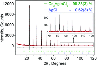
Fig. 1 shows the observed, calculated, and the difference of the powder XRD pattern for Rietveld refinement of Cs2AgInCl6. Based on the Rietveld refinement results, almost all peaks were indexed to the cubic cell (Fm3m) with parameters close to those of Cs2AgAuCl6 (elpasolite-type structure) besides small peaks belonging to the AgCl phase (wt 0.62(3)%). Cs2AgInCl6 belongs to the expected lead-free double perovskite structure, which crystallized in a cubic unit cell with the space group Fm3m and cell parameters a = 10.48059(5) and Z = 4. The detailed structural parameters revealed from the refinement of Cs2AgInCl6 are given in Table 1, and the crystallographic information file (CIF) is given in the ESI†. As a comparison, the cell parameters of some lead-free double perovskites recently reported for potential optoelectronic application are summarized in Table 1. Cs2AgBiCl6, Cs2AgBiBr6, Cs2SnI6 and (CH3NH3)2AgBiBr6 share the space group Fm3m with Cs2AgInCl6, while CsRbSnI6 and (CH3NH3)2KBiCl6 have the space groups Pmn21 and R3m, respectively.| Compound | Sp. Gr | a, Å | V, Å3 | Z | Band gap, eV (measured/calculated) | Ref. |
|---|---|---|---|---|---|---|
| Cs2AgInCl6 | Fm3m | 10.48059(5) | 1151.22(2) | 4 | 3.23/3.33 | This work |
| 10.467(1) | 1147.01 | 4 | 3.3/2.7 ± 0.6 | 23 | ||
| Cs2AgBiCl6 | Fm3m | 10.7774(2) | 1251.82(6) | 4 | 2.77/2.62 | 20 |
| 10.6959(−0.75%) | 1223.64(−2.25%) | 4 | — | 7 | ||
| 10.777(5) | 1251.68 | 4 | 2.2/2.4 | 21 | ||
| Cs2AgBiBr6 | Fm3m | 11.2711 (1) | 1431.86(5) | 4 | 2.19/2.06 | 20 |
| 11.2011(−0.43%) | 1405.342(−1.29%) | 4 | — | 7 | ||
| 11.264(5) | 1429.15 | 4 | 1.9/1.8 | 21 | ||
| 11.2499(4) | 1423.79(9) | 4 | 1.83/ | 22 | ||
| Cs2SnI6 | Fm3m | 11.6276(9) | 1572.1(2) | 4 | 1.26/1.3 | 31 |
| Fm3m | 11.6276(9) | 1572.1(2) | 4 | 1.62/1.6 | 32 | |
| Fm3m | 11.65 | 1581.17 | 4 | — | 33 | |
| CsRbSnI6 | Pmn21 | a = 8.2608, b = 12.1507, c = 8.7913 | 882.42 | 2 | —/1.58 | 34 |
| (CH3NH3)2AgBiBr6 | Fm3m | 11.6370(1) | 1575.8799 | 4 | 2.02/2.02 | 35 |
| (CH3NH3)2KBiCl6 | R3m | a = 7.8372(2) | 1116.72(7) | 3 | 3.04/3.02 | 36 |
| c = 20.9938(2) |
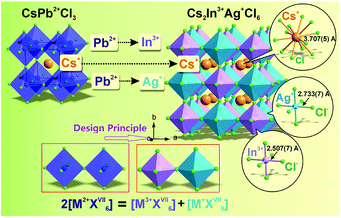
As was proposed and discussed previously,10 the design principle of chemical unit cosubstitution enabled the construction of the lead-free double perovskite (Cs2AgInCl6) from the famous all-inorganic perovskite (CsPbCl3), and the general schematic diagram (2[M2+XVII6] = [M3+XVII6] + [M+XVII6]) is depicted in Fig. 2. Also, the CsPbCl3 and Cs2AgInCl6 crystal structures are shown in Fig. 2. In order to keep the total number of unchanged valence electrons at B sites, two divalent Pb2+ ions are replaced by one monovalent ion Ag+ and one trivalent ion In3+. It is clearly found that the double perovskite structure of Cs2AgInCl6 is obtained by alternating [AgCl6] and [InCl6] octahedra in all three directions forming a 3D framework, so that the AgIn sublattice is typically referred to as ordered rock-salt like NaCl. The In–Cl bond length (2.507(7) Å) is slightly shorter than that of Ag–Cl (2.733(7) Å), as expected.
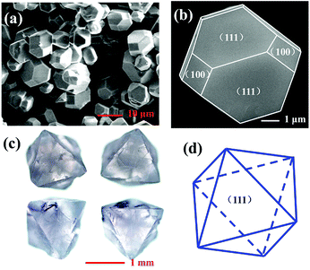
Fig. 3a presents the typical scanning electron microscope (SEM) images of the as-prepared Cs2AgInCl6 microcrystals obtained by hydrothermal reaction for 12 h. It can be seen that the product is composed of some regular rhombic dodecahedral particles with the size between 5 and 12 μm. A magnified image of the rhombic dodecahedron for the single crystal particle is presented in Fig. 3b, which exhibits that Cs2AgInCl6 shows typical fcc-crystal features and the tetradecahedral crystallization habit forming truncated octahedra. Moreover, the exhibited facets of Cs2AgInCl6 were determined to be (111) and (100). Fig. 3c represents photographs of Cs2AgInCl6 single crystals obtained via an optical microscope, with its characteristic gray transparent color indicating a band gap in the invisible range. A long crystal growth time of 72 h via the hydrothermal method enabled the formation of millimeter-sized regular octahedral single crystals with the edge length of about 1.5 mm. The exhibited fates of Cs2AgInCl6 were determined to be (111), as shown in Fig. 3d. It is expected that the Cs2AgInCl6 single crystal size can be further increased through optimization of the processing conditions.
3.2 Optical properties
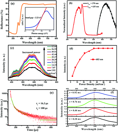
To investigate the optical band gaps, the UV-vis diffuse reflectance spectra of Cs2AgInCl6 were measured (Fig. 4a). The band gap of Cs2AgInCl6 can be estimated according to eqn (2)37| [F(R∞)hv]n = A(hv − Eg) | (2) |
| F(R∞) = (1 − R)2/2R = K/S | (3) |
The normalized PL and PLE spectra of Cs2AgInCl6 are presented in Fig. 4b. As shown in this figure, Cs2AgInCl6 (monitored at 635 nm) has a broad PLE spectrum, and covers the spectral region from 260 nm to 420 nm, which consists of two distinct bands at about 335 nm and 370 nm. Under 370 nm irradiation, the PL spectrum of Cs2AgInCl6 exhibits a broad red emission band peaking at 635 nm, which is attributed to the photo-induced defects in Cs2AgInCl6, and this result agrees well with the recent report.23 Furthermore, to verify the origin of the emission centers, the power-dependent photoluminescence spectra (Fig. 4c) were measured. Commonly, the band edge emission intensity monotonically increases, but the intensity of defect emission will reach a maximum depending on increasing excitation power. As seen in Fig. 4d, the emission intensity at 603 nm of Cs2AgInCl6 saturates at the excitation power density of 35.37 mJ cm−2, and this verified that the emission centers belong to the defect type states, but not intrinsic band edge states. In Fig. 4e, the decay curve of Cs2AgInCl6 was fitted with a biexponential decay function giving a fast initial drop with a lifetime of 16.3 μs and a slower decay with a long lifetime of 100 μs. In addition, time-resolved emission spectra of Cs2AgInCl6 were measured with a delay time ranging from 0.28 to 0.92 ms (Fig. 4f). At t = 0.28 ms, we see a well-defined PL peak centered around 596 nm (2.08 eV), with a FWHM of 108 nm (11.48 eV). As the delay time increases from 0.28 to 0.92 ms, this peak noticeably shifts from 596 nm to 607 nm, attributed to there being filled subgap states on this timescale. Such complex decay behavior is similar to that found in other lead-free double perovskites, Cs2AgBiCl6 and Cs2AgBiBr6, and this was attributed to surface/defect states and fundamental nonradiative carrier recombination.22
3.3 Band structure and optical absorption calculations
Fig. 5a shows the electronic band structure of Cs2AgInCl6 calculated in the framework of density functional theory (DFT). The details of the calculations are available in the Experimental section and the atomic structure used for the calculations is based on the X-ray diffraction data. As DFT usually underestimates the band gap, we then use the hybrid functional (HSE06) to correct the band gap. After the correction with HSE06 (α = 0.4), the calculated band gap is 3.33 eV, which is similar to the experimental value. For comparison, the experimental and calculated band gaps of other halide double perovskites are given in Table 1. Cs2AgInCl6 is found to be a direct gap material by the electronic structure calculation (see Fig. 5a), as compared to the indirect gap material Cs2AgBiCl6 with a lone-pair valence band appearing when In3+ is replaced by Bi3+.20 We note that although the first conduction band is quite dispersive, the first valence band is rather flat along the Γ–X direction. Thus, Cs2AgInCl6 could have very different transport properties for electrons and holes.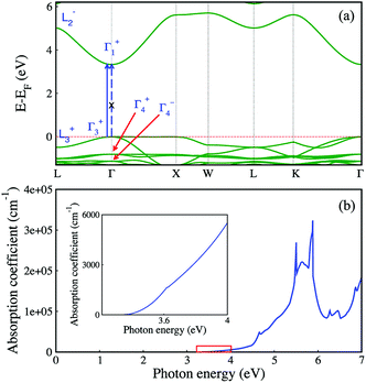 | ||
| Fig. 5 Electronic structure (a) and optical absorption coefficient (b) of Cs2AgInCl6 from DFT with the band gap corrected from HSE06. | ||
We further analyze the optical transitions in Cs2AgInCl6 and note that the optical transition between band edge states at the Γ point is forbidden (see the dashed blue arrow in Fig. 5a), because the band edge states have the same parity (see the labels of states in blue in Fig. 5a; plus/minus signs indicate parity eigenvalues).39 However, the band edge states at the L point have opposite parities (see Fig. 5a) and their optical transition is allowed.39 Furthermore, the band edge optical transitions for the k points between Γ and L are also allowed (see the solid blue arrow in Fig. 5a),39 along with other k points near Γ. Given the neglectable contribution of the joint density of states from the Γ point comparing to the contribution from nearby k points, the fundamental band gap of Cs2AgInCl6 could still be defined as the optical gap. Although the parity-forbidden optical transition at Γ does lead to very weak optical absorption near the band gap, as shown in Fig. 5b, the absorption coefficient decreases linearly as the photon energy approaches the fundamental band gap (see the inset of Fig. 5b), which indicates that the fundamental band gap could be measured as an optical gap. Indeed, the optical gap found in our experiment (3.23 eV) is close to the calculated fundamental band gap (3.33 eV). Furthermore, the optical transition between the band edge states near the Γ point is reflected in the PLE spectrum in Fig. 4b. In our HSE06 calculations, we use a higher percentage of exact Fock exchange that leads to a larger band gap than the default value of 25%, which is needed for ionic compounds.40 For comparison, we calculate the band gap from HSE06 using the default percentage of exact Fock exchange (25%) that is ∼2.5 eV and much larger than the energy of the PL peak (2.08 eV). As shown in Fig. 5a, the first two (third) valence-band (VB) states at Γ have the same (opposite) parities as the first conduction-band (CB) state; therefore from the point of view at the Γ point, the non-zero optical-transition oscillator strength starts at the energy gap between the third VB state and the first CB state at Γ. This energy gap is 4.46 eV (3.57 eV) for 40% (25%) of exact Fock exchange, and both are much larger than the experimental band gap (3.23 eV). As discussed above, the measured PL peak near 2.08 eV can be attributed to defect states. Since Ag and In have the same first- and second-shell local environments, i.e. Cl6 octahedra and Cs8 polyhedra, Ag–In anti-site defect could be a relevant defect for the measured PL peak. We calculated the band gap (total energy) of a 2 × 2 × 2 supercell of Cs2AgInCl6 with an Ag–In anti-site defect, and found that the defective supercell is 740 meV (15 meV per atom) lower in the band gap (higher in energy) than Cs2AgInCl6; thus the formation of Ag–In anti-site defect could significantly decrease the energy gap. The intrinsic emission from the CB to VB optical transitions in Cs2AgInCl6 may not be seen in the PL spectrum if the carriers can quickly relax into the defect states. Other defect states in Cs2AgInCl6 may also be relevant to the measured PL spectrum with two types of decay behaviors (see Fig. 4b), which are beyond the scope of this work. The two types of decay behaviors with very long lifetimes (16.3 μs and 100 μs) that are much longer than the fundamental nonradiative carrier recombination lifetime (660 ns) in Cs2AgBiBr6 (ref. 22) at the indirect band gap may not be related to the allowed weak optical transitions (radiative rather than nonradiative) at the k points near Γ, if one assumes that the fundamental band gap of Cs2AgInCl6 is 2.08 eV. Therefore, we believe that the fundamental band gap of Cs2AgInCl6 is around 3.23 eV instead of 2.08 eV, given also that the 40% exact Fock exchange used in our calculation that produces a band gap of 3.33 eV is smaller than the percentage used in ref. 40 as fitted to experimental band gaps. Although there is a debate on the value of the “optical gap” in Cs2AgInCl6, the commonly found interesting feature of the fundamental band gap in Cs2AgInCl6 constitutes a prototypic band gap of materials that is optically active without the help of other quasi-particles such as phonons. However, its optical transition probability is extremely low, analogous to phonon-assistant transitions. Therefore, the optical transition in this prototypic compound Cs2AgInCl6 has the slowness properties of quasi-particle assisted transition, but it avoids the involvement of quasi-particle scatterings. Slow and rare optical processes are important for novel technologies that involve fewer photons, such as single-photon quantum information, shedding light on the potential technological applications of the miserably weak optically allowed fundamental band gap in Cs2AgInCl6.
3.4 Chemical, light and thermal stability
To determine the light and chemical stability of Cs2AgInCl6, selected Cs2AgInCl6 samples were analyzed by powder XRD and UV-vis diffuse reflectance spectroscopy for the as-prepared state (0 day) and after exposure to an ambient atmosphere under both light and moisture conditions for 7 days, 14 days and 26 days. It is found that there is no obvious difference in the chemical and thermal stability depending on the crystal size. Therefore, as can be seen in Fig. 6a, with increasing the exposure time, a gradual evolution of the AgCl impurity peak was noticed. As for the reflectance spectrum, there is no apparent change in the curve shape (as also compared with the spectral profile in Fig. 4a) except for the slight intensity decline.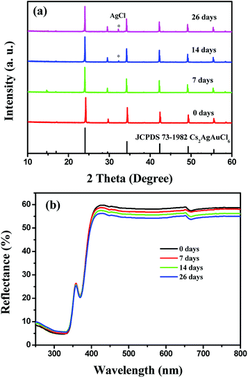 | ||
| Fig. 6 XRPD patterns (a) and UV-vis diffuse reflectance spectra (b) of Cs2AgInCl6 after 7 days, 14 days and 26 days of exposure to light and moisture conditions. | ||
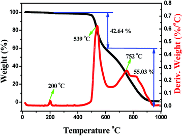
Considering thermal stability which is also an important property for halide perovskites for the future applications, we carried out thermogravimetric and differential scanning calorimetry (TG-DSC) analysis of the as-prepared Cs2AgInCl6 powder sample (Fig. 7), and weight loss occurring in three steps can be clearly found. The first step centered at around 200 °C with the small weight loss is ascribed to the release of adsorbed water from the sample surface. Moreover, the next serious weight loss is 42.64 wt%, which mainly occurred from 400 to 615 °C. Herein, the obvious exothermic peak shown on the DSC curve is centered at about 539 °C, which is connected to the evaporation of CsAgCl2. It is noticed that CsAgCl2 constitutes 44.45% of the total weight in Cs2AgInCl6, and therefore, the decomposition process might be described as follows: Cs2AgInCl6 → CsAgCl2 + CsInCl4. Finally, the third weight loss of 55.03 wt%, observed at 615–1000 °C and centered at around 752 °C, is attributed to the evaporation of CsCl and AgCl, which correspond to 55.55% of the total weight in Cs2AgInCl6, and the decomposition reaction equation could proceed according to the following scheme: CsInCl4 → CsCl + InCl3.41 The above results indicate that Cs2AgInCl6 is relatively stable at about 400 °C. After that, some obvious decomposition reaction occurs enabling the materials to lose functionality completely.
4 Conclusion
In conclusion, lead-free halide double perovskite, Cs2AgInCl6, was prepared through a hydrothermal method, and its crystal sizes from 5 to 1.5 mm can be controlled via different experimental conditions with well-defined crystal facets. Single crystals of Cs2AgInCl6 under an optical microscope demonstrated a characteristic gray transparent contrast indicating a band gap in the invisible range. While the emission observed from the PL spectrum and time-resolved spectra should be attributed to the photo-induced defects in Cs2AgInCl6. The optical band gap was determined to be 3.23 eV via the UV-vis measurement, while the band structure and optical absorption calculations verified that the evaluated band gap is 3.33 eV with a direct band gap showing good agreement. Also, the Cs2AgInCl6 double perovskite demonstrates excellent moisture, light and heat stability, which shows great potential for photovoltaic and other optoelectronic applications via further band gap engineering.Acknowledgements
The present work was supported by the National Natural Science Foundation of China (Grants 91622125 and 51572023), Natural Science Foundations of Beijing (2172036), and Fundamental Research Funds for the Central Universities (FRF-TP-16-002A3). XZ acknowledges the support from the National Key Research and Development Program of China Grant No. 2016YFB0700700.Notes and references
- (a) X.-G. Zhao, D. Yang, Y. Sun, T. Li, L. Zhang, L. Yu and A. Zunger, J. Am. Chem. Soc., 2017, 139, 6718 CrossRef CAS PubMed; (b) G. Xing, N. Mathews, S. Sun, S. S. Lim, Y. M. Lam, M. Grätzel, S. Mhaisalkar and T. C. Sum, Science, 2013, 342, 344 CrossRef CAS PubMed.
- N. K. Noel, S. D. Stranks, A. Abate, C. Wehrenfenning, S. Gurnera, A. A. Haghighirad, A. Sadhanala, G. E. Eperon, S. K. Pathak, M. B. Johnston, A. Petrozza, L. M. Herz and H. J. Snaith, Energy Environ. Sci., 2014, 7, 3061 CAS.
- Y. Fang, Q. Dong, Y. Shao, Y. Yuan and J. Huang, Nat. Photonics, 2015, 9, 679 CrossRef CAS.
- D. H. Fabini, T. Hogan, H. A. Evans, C. C. Stoumpos, M. G. Kanatzidis and R. Seshadri, J. Phys. Chem. Lett., 2016, 7, 376 CrossRef CAS PubMed.
- Q. A. Akkerman, V. D'Innocenzo, S. Accornero, A. Scarpellini, A. Petrozza, M. Prato and L. Manna, J. Am. Chem. Soc., 2015, 137, 10276 CrossRef CAS PubMed.
- D. H. Fabini, G. Laurita, J. S. Bechtel, C. C. Stoumpos, H. A. Evans, A. G. Konotos, Y. S. Raptis, P. Falaras, A. Vander Ven and M. G. Kanatzidis, J. Am. Chem. Soc., 2016, 138, 11820 CrossRef CAS PubMed.
- F. Giustino and H. J. Snaith, ACS Energy Lett., 2016, 1, 1233 CrossRef CAS.
- C. C. Stoumpos, L. Frazer, D. J. Clark, Y. S. Kim, S. H. Rhim, A. Freeman, J. B. Ketterson, J. I. Jang and M. G. Kanatzidis, J. Am. Chem. Soc., 2015, 137, 6804 CrossRef CAS PubMed.
- Z. G. Xia and K. R. Poeppelmeier, Acc. Chem. Res., 2017, 50, 1222 CrossRef CAS PubMed.
- Z. G. Xia, C. G. Ma, M. S. Molokeev, Q. L. Liu, K. Rickert and K. R. Poeppelmeier, J. Am. Chem. Soc., 2015, 137, 12494 CrossRef CAS PubMed.
- X. G. Zhao, J. H. Yang, Y. H. Fu, D. W. Yang, Q. L. Xu, L. P. Yu, S. H. Wei and L. J. Zhang, J. Am. Chem. Soc., 2017, 139, 2630 CrossRef CAS PubMed.
- S. Vasala and M. Karppinen, Prog. Solid State Chem., 2015, 43, 1 CrossRef CAS.
- R. F. Berger and J. B. Neaton, Phys. Rev. B: Condens. Matter Mater. Phys., 2012, 86, 165211 CrossRef.
- I. N. Flerov, M. V. Gorev, K. S. Aleksandrov, A. Tressaud, J. Grannec and M. Couzi, Mater. Sci. Eng., R, 1998, 24, 81 CrossRef.
- L. R. Morss, M. Siegal, L. Stenger and N. Edelstein, Inorg. Chem., 1970, 9, 1771 CrossRef CAS.
- M. M. Abraham, J. L. Boldú, B. E. Cabrera, R. J. Gleason and E. Muñoz, J. Phys. Chem. Solids, 2004, 65, 1087 CrossRef CAS.
- F. Prokert and K. S. Aleksandrov, Phys. Status Solidi B, 1984, 124, 503 CrossRef CAS.
- F. Pelle, B. Blanzat and B. Chevalier, Solid State Commun., 1984, 49, 1089 CrossRef CAS.
- W. M. A. Smit, G. J. Dirksen and D. J. Stufkens, J. Phys. Chem. Solids, 1990, 51, 189 CrossRef CAS.
- E. T. Mcclure, M. R. Ball, W. Windl and P. M. Woodward, Chem. Mater., 2016, 28, 1348 CrossRef CAS.
- G. Volonakis, M. R. Filip, A. A. Haghighirad, N. Sakai, B. Wenger, H. J. Snaith and F. Giustino, J. Phys. Chem. Lett., 2016, 7, 1254 CrossRef CAS PubMed.
- A. H. Slavney, T. Hu, A. M. Lindenberg and H. I. A. Karunadasa, J. Am. Chem. Soc., 2016, 138, 2138 CrossRef CAS PubMed.
- G. Volonakis, A. A. Haghighirad, R. L. Milot, W. H. Sio and M. R. Filip, J. Phys. Chem. Lett., 2017, 8, 772 CrossRef CAS PubMed.
- Bruker AXS, TOPAS V4: General Profile and Structure AnalysisSoftware for Powder Diffraction Data – User's Manual, Bruker AXS, Karlsruhe, Germany, 2008 Search PubMed.
- W. Kohn and L. J. Sham, Phys. Rev., 1965, 140, A1133 CrossRef.
- G. Kresse and D. Joubert, Phys. Rev. B: Condens. Matter Mater. Phys., 1999, 59, 1758 CrossRef CAS.
- J. P. Perdew, K. Burke and M. Ernzerhof, Phys. Rev. Lett., 1996, 77, 3865 CrossRef CAS PubMed.
- G. Kresse and J. Furthmüller, Comput. Mater. Sci., 1996, 6, 15 CrossRef CAS.
- G. Kresse and J. Furthmuller, Phys. Rev. B: Condens. Matter Mater. Phys., 1996, 54, 11169 CrossRef CAS.
- J. Heyd, G. E. Scuseria and M. E. Ernzerhof, J. Chem. Phys., 2003, 118, 8207 CrossRef CAS.
- B. H. Lee, C. C. Stoumpos, N. J. Zhou, F. Hao, C. Malliakas, C. Y. Yeh, T. J. Marks, M. G. Kanatzidis and R. P. H. Chang, J. Am. Chem. Soc., 2014, 136, 15379 CrossRef CAS PubMed.
- B. Saparov, J. P. Sun, W. W. Meng, Z. W. Xiao, H. S. Duan, O. Guanawan, D. Shin, I. G. Hill, Y. F. Yan and D. B. Mitzi, Chem. Mater., 2016, 28, 2315 CrossRef CAS.
- A. F. Wang, X. X. Yan, M. Zhang, S. B. Sun, M. Yang, W. Shen, X. O. Pan, P. Wang and Z. T. Deng, Chem. Mater., 2016, 28, 8132 CrossRef CAS.
- G. Y. Gou, J. Young, X. Liu and M. Rondinelli, Inorg. Chem., 2017, 56, 26 CrossRef CAS PubMed.
- F. X. Wei, Z. Y. Deng, S. J. Sun, F. H. Zhang, D. M. Evans, G. Kieslich, S. Tominaka, M. A. Carpenter, J. Zhang, P. D. Bristowe and A. K. Cheetham, Chem. Mater., 2017, 29, 1089 CrossRef CAS.
- F. X. Wei, Z. Y. Deng, S. J. Sun, F. Xie, G. Kieslich, D. M. Evans, M. A. Carpenter, P. D. Bristowe and A. K. Cheetham, Mater. Horiz., 2016, 3, 328 RSC.
- J. Wang, S. B. Wang and Q. Su, J. Solid State Chem., 2004, 177, 895 CrossRef CAS.
- Z. G. Xia, Y. Y. Zhang, M. S. Molokeev and V. V. Atuchin, J. Phys. Chem. C, 2013, 117, 20847 CAS.
- W. W. Meng, X. M. Wang, Z. W. Xiao, J. B. Wang, D. Mitzi and Y. F. Yan, J. Phys. Chem. Lett., 2017, 8, 2999 CrossRef CAS PubMed.
- D. Yang, J. Lv, X. Zhao, Q. Xu, Y. Fu, Y. Zhan, A. Zunger and L. Zhang, Chem. Mater., 2017, 29, 524 CrossRef CAS.
- F. P. Emmenegger, J. Cryst. Growth, 1972, 17, 31 CrossRef CAS.
Footnote |
| † Electronic supplementary information (ESI) available: The crystallographic information file (CIF) of Cs2AgInCl6. See DOI: 10.1039/c7ta04690a |
| This journal is © The Royal Society of Chemistry 2017 |

