 Open Access Article
Creative Commons Attribution 3.0 Unported Licence
Organically modified clay with potassium copper hexacyanoferrate for enhanced Cs+ adsorption capacity and selective recovery by flotation†
Huagui
Zhang
 *a,
Yun Kon
Kim
b,
Timothy N.
Hunter
a,
Andrew P.
Brown
a,
Jae W.
Lee
b and
David
Harbottle
 *a
*a
aSchool of Chemical and Process Engineering, University of Leeds, Leeds, LS2 9JT, UK. E-mail: d.harbottle@leeds.ac.uk; prehz@leeds.ac.uk
bChemical and Biomolecular Engineering, Korean Advanced Institute of Science and Technology, Daejeon, Republic of Korea
First published on 3rd July 2017
Abstract
The selective capture of mobile radioactive nuclides, such as 137Cs+, is crucial to the clean-up and remediation of contaminated environments. While remediation remains a challenging task, the current study considers novel organo-clay composites containing potassium copper hexacyanoferrate (KCuHCF) as a viable option for large-scale clean-up. A three-step synthesis has been demonstrated whereby pristine montmorillonite clay was readily modified to incorporate KCuHCF nanoparticles for enhanced and selective Cs+ removal from aqueous environments. Alkyldiamine (DT) was used as an organic modifier to intercalate the clay and provided chelating sites to anchor copper onto the clay matrix, from which KCuHCF nanoparticles were subsequently grown in situ via the coordination of hexacyanoferrate precursors with the immobilized copper ions. The organo-clay–HCF composite particles exhibited a superior Cs+ adsorption capacity (qm = 206 mg g−1), twice that of the pristine clay. The enhanced performance also extended to high Cs+ selectivity in seawater, with the organo-clay–HCF composites demonstrating Cs+ selectivity values in excess of 105 mL g−1, two orders of magnitude greater than the pristine clay. Organo modification of the clay particles reduced the particle wettability, thus facilitating the separation of Cs-loaded composite particles from aqueous environments by collector-less flotation. Batch flotation experiments showed recovery efficiencies of the Cs-loaded composite particles of up to 90%, which was in great contrast to the low recovery of less than 15% for the Cs-loaded pristine montmorillonite. The current study provides a new concept for the treatment of contaminated aqueous environments.
1. Introduction
Nuclear power is seen as a viable option to address the global energy challenge due to efficient and clean energy production. While the industry is heavily regulated, risks of nuclear incident, such as that witnessed at the Fukushima Daiichi nuclear plant, must be planned for, as they can result in substantial environmental liability.1 The release of radioactive isotopes, in particular 134Cs+ and 137Cs+, can result in a significant biohazard with the long-lived radionuclides (half-life ∼ 30 years) accumulating in the environment, and total depletion of radioactivity requiring approximately 1000 years.2 Additionally, a significant volume of contaminated effluent is produced from normal nuclear power operations (e.g. within fuel cooling plants) which must also be treated on an ongoing basis. Cs+ is highly soluble in water and readily migrates with the potential to produce wide spread contamination of land and water systems.Several remediation strategies have been deployed to recover Cs+ from radioactive wastes including chemical precipitation, membrane extraction, reverse osmosis, solvent extraction and ion exchange.3 Ion exchange by selective adsorbent is a proven route to separate Cs+ from aqueous environments, forming a concentrated waste more suitable for disposal. Accordingly, a series of inorganic Cs+ adsorbents have been developed, among which zeolites,4 crystalline silicotitanate,5,6 vanadosilicate7 and chalcogenides,2,8,9 have been studied in detail due to high Cs+ selectivity and excellent removal efficiencies. Nevertheless, the complexity of synthesis and cost-inefficiency greatly limit application for large-scale nuclear waste clean-up and remediation. In contrast, natural clay minerals which have also been used as adsorbents for radionuclides (e.g. Cs+, Sr2+, Co2+)10,11 and other hazardous contaminants are readily available, low cost, and therefore suitable for scale-up. In particular, montmorillonite, a member of the smectite clays composed of two tetrahedral silica sheets surrounding a central octahedral sheet of alumina in a 2-1 layered structure, has been extensively adopted as a very efficient Cs+ adsorbent with an adsorption capacity in the range 57–104 mg g−1.10–13 This relatively high adsorption capacity results from favourable structural properties including high cation exchange capacity (CEC), large surface area, high swelling capacity, good chemical and mechanical stability.10,14
An alternative group of adsorbents that are cost-effective and show high adsorption capacity are Prussian blue analogues (PBAs), namely the hexacyanoferrates (HCFs) of transition metals, wherein potassium copper hexacyanoferrate (KCuHCF) provides higher Cs+ selectivity compared to other metal hexacyanoferrates.15 Hexacyanoferrate(II) is an agent of high Cs+ affinity and selectivity, with the small hydrated ions such as Cs+ able to permeate through the cubic structure, while the larger competing ions are blocked from accessing the sorption sites.15–18 However, the fine particle size of this type of adsorbent makes it difficult to separate from aqueous environments, so it is generally incorporated within supporting materials for effective Cs+ adsorption and removal.15,19 The main supporting materials are either polymer composites or mesoporous silica, both of which show limited Cs+ adsorption capacity. Even though both the smectite clay and HCF have demonstrated relatively high Cs+ uptake ability, to the best of our knowledge, reports of nanocomposites immobilizing HCF onto clays remain surprisingly scarce.20
In the current study we report an original and facile synthesis route for organo-clay–KCuHCF composite adsorbents. Montmorillonite clay was organically intercalated with ethylhexadecyldimethyl-ammonium-bromide and decorated with alkyldiamine, followed by the in situ synthesis of KCuHCF. Cationic surfactant was firstly intercalated into the clay interlayer to immobilize the alkyldiamine, which acts as a metal chelator for a Cu2+–diamine complex, serving as an anchoring point for KCuHCF growth. This type of incorporation, with organo-clay being the supporting matrix, retains the high Cs+ adsorption capacity of the clay and KCuHCF, along with modifying the surface of the clay to be hydrophobic and enable easy recovery of the composite particles by flotation. In the absence of clays the nano-sized KCuHCF particles remain dispersed in suspension and unrecoverable, but the apparent growth in particle size through incorporation with clays, and the increased surface hydrophobicity provide realization for a new concept in Cs+ removal from contaminated aqueous environments. The structure and chemistry of the composite adsorbents were characterized using a series of techniques including powder X-ray diffraction (XRD), Fourier transform infrared spectroscopy (FTIR), X-ray photoelectron spectroscopy, scanning electron microscopy (SEM) and transmission electron microscopy (TEM). Component loadings were quantified by thermogravimetric analysis (TGA). Cs+ adsorption was studied by measuring the kinetics and adsorption capacity in environments of varying pH and multi-component ionic solutions. Finally, the flotation performance of the Cs-loaded composites was studied using a laboratory batch flotation cell, with recovery performance measured as a function of the DT concentration.
2. Experimental
2.1 Chemicals
Montmorillonite clay (abbreviated as Mont., a naturally occurring mineral) of ∼200 mesh (<74 μm) was purchased from Alfa Aesar. Ethylhexadecyldimethylammonium-bromide (EHDA-Br; abbreviated as EH) with Mw of 378.5 g mol−1 was purchased from Merck Millipore (purity > 98.0%). The metal ligand of alkyl-1,3-diaminopropane (Duomen-T; abbreviated as DT) with Mw of 350 g mol−1, alkyl group (R) ranging from C12 to C18, was supplied by Akzo Chemicals (batch no. 1197752). Chemical structures of the EH and DT are given in Fig. 1a. Potassium hexacyanoferrate(II) (K4[Fe(CN)]6·3H2O, ACS reagent, ≥99%), copper sulfate (CuSO4·5H2O, Reagent Plus, ≥99%) and cesium chloride (CsCl, analytical grade) were purchased from Sigma-Aldrich and used as received.The cation exchange capacity (CEC) of the montmorillonite clay was found to be 90 meq./100 g. The CEC was determined by the sorption of 0.01 M Cu(II)–triethylenetetramine complex [Cu·Trien]2+ following the procedure outlined by Honty et al.21 The concentration of [Cu·Trien]2+ was measured at 577 nm by UV spectroscopy (UV-1800 SHIMADZU). The BET specific surface area of the montmorillonite clay was determined to be 29.85 m2 g−1 by N2 adsorption isotherm using a Micromeritics TriStar 3000. The chemical composition of the montmorillonite clay was measured by X-ray fluorescence (XRF) spectrometry to be 2.20 wt% Na2O, 2.39 wt% MgO, 20.80 wt% Al2O3, 66.86 wt% SiO2, 0.06 wt% P2O5, 0.40 wt% SO3, 0.70 wt% K2O, 1.66 wt% CaO, 0.16 wt% TiO2, 0.05 wt% MnO, 4.57 wt% Fe2O3, 0.03 wt% CuO, 0.01 wt% ZnO, 0.06 wt% SrO and 0.05 wt% ZrO2.
2.2 Synthesis
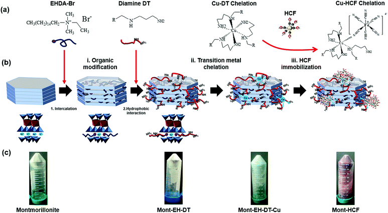
To organically modify the clay particles and generate reacting sites for HCF growth, a cationic surfactant of alkylammonium salt (EHDA-Br) was first used to intercalate the clay particles. While the irreversible binding of the cationic surfactant to the clay interlayers has not been verified in the current study, this likely interaction was previously reported.22 The intercalated EHDA-Br molecules provided sites to anchor the metal ligand alkyldiamine (DT) through hydrophobic interactions. Without the inclusion of EHDA-Br, DT molecules were unable to bind to the clay particles as evidenced by previous research.23 Immobilization of DT onto clay particles promotes both the hydrophobic modification of the clay particles and generates binding sites for the chelation of transition metals via a metal–diamine coordination mechanism, see Fig. 1a. 0.5 mL of 10 mM EHDA-Br solution was added dropwise to 20 mL of stock fractioned suspension (EH/Mont. ratio: 0.0125 mmol g−1) in a 50 mL polypropylene centrifuge tube before agitating at 150 rpm in an orbital shaker for 2 h. The suspension was then centrifuged at 11![[thin space (1/6-em)]](https://www.rsc.org/images/entities/char_2009.gif) 000 rpm for 15 min to separate the particles from any excess surfactant in the supernatant and washed a further 3 times in Milli-Q water. The particles were then re-dispersed in a series of 20 mL DT solutions, with concentrations varying from 0.1 mM to 50 mM, details of which are specified in Table 1. The DT solutions were obtained by a series of dilutions from 0.5 M DT, and the solution pH was fixed between 8.5 and 9.0 to deprotonate both amine groups and minimize the possible displacement of pre-adsorbed EH, while ensuring that adsorption occurs through hydrophobic anchoring. The particle suspensions were shaken for 12 h before being rinsed in Milli-Q water a further 3 times, following the same procedure as outlined for removing excess DT.
000 rpm for 15 min to separate the particles from any excess surfactant in the supernatant and washed a further 3 times in Milli-Q water. The particles were then re-dispersed in a series of 20 mL DT solutions, with concentrations varying from 0.1 mM to 50 mM, details of which are specified in Table 1. The DT solutions were obtained by a series of dilutions from 0.5 M DT, and the solution pH was fixed between 8.5 and 9.0 to deprotonate both amine groups and minimize the possible displacement of pre-adsorbed EH, while ensuring that adsorption occurs through hydrophobic anchoring. The particle suspensions were shaken for 12 h before being rinsed in Milli-Q water a further 3 times, following the same procedure as outlined for removing excess DT.
| Sample label | Initial DT conc. (mM) | Organic loadinga (% w/w) | Form of immobilized HCFb | HCF contenta (% w/w) | q m of organo-clay (mgCs g−1 organo-clay)c | Theoretical exchange capacityd (mgCs g−1 composite) |
|---|---|---|---|---|---|---|
| a Estimated from the TGA data (Fig. S2). b Estimated from XPS analysis. c Obtained from Langmuir isotherm fitting of the experimental data, see Fig. S3. d Based on K+ content in the immobilized HCF and the qm of organo-clay matrix. | ||||||
| Pristine Mont. | 0 | 0 | — | 0 | 103 | 103 |
| Mont–HCF(DT0.1) | 0.1 | 1.2 | K1.08Cu1.46Fe(CN)6 | 15.4 | 123 | 206 |
| Mont–HCF(DT0.8) | 0.8 | 1.8 | K1.76Cu1.12Fe(CN)6 | 16.0 | 97 | 188 |
| Mont–HCF(DT8) | 8 | 11.8 | K1.60Cu1.24Fe(CN)6 | 25.4 | 0 | 154 |
| Mont–HCF(DT50) | 50 | 40.4 | K1.66Cu1.17Fe(CN)6 | 35.8 | 0 | 225 |
2.3 Particle characterizations
Powder X-ray diffraction (XRD) patterns were obtained using a Bruker D8 X-ray diffractometer fitted with a LynxEye detector, using a Cu Kα (1.54 Å) radiation source operating at 40 kV and 40 mA, calibrated against a silica standard. Each sample was scanned over a 2θ angle range of 4° to 49.98° with a step size of 0.03299° at 2 s per step. Fourier transform infrared (FT-IR) spectra were collected using a Nicolet iS10 FT-IR spectrometer equipped with a deuterated triglycine sulphate (DTGS) KBr detector. A minimum of 36 scans were performed at a resolution 4 cm−1 in the range of 600 cm−1 to 4000 cm−1. X-ray photoelectron spectroscopy (XPS) analysis was completed using a Thermo K-Alpha XPS system with a monochromated Al Kα X-ray source. An electron/ion gun was used to compensate for charge build-up on the sample during measurement. For morphological characterization, the as-prepared composite particles were deposited onto an SEM stub and dried in a desiccator before imaging using a Field Emission Gun Scanning Electron Microscope (FEG-SEM; LEO1530 GEMINI, Carl Zeiss Inc.). Transmission electron microscopy (TEM) measurements were completed using a FEI Tecnai TF20 FEG-TEM operated at 200 kV and fitted with a Gatan Orius SC600A CCD camera. Samples were prepared by depositing one drop of the particle suspension on an amorphous carbon film supported by a copper grid for TEM analysis (Agar Scientific Ltd). Elemental mapping of the modified clay particles in both the FEG-TEM and FEG-SEM was completed using energy dispersive X-ray spectroscopy (EDX) with an Oxford Instruments 80 mm2 X-Max SD detector and INCA 350 software. Thermogravimetric analysis (TGA) was performed using ∼20 mg samples in a Mettler-Toledo TGA-DSC1 instrument, with a heating profile from 30 °C to 1000 °C using a heating rate of 10 °C min−1 under steady N2 flow (50 mL min−1). The collected data were blank subtracted.2.4 Batch adsorption experiments
The composite particles were stored wet at a solid concentration of 33.3 g L−1. Wet storage avoided any issues of particle clumping and mitigated the need for high energy re-dispersion in water. All batch adsorption experiments were completed using plastic vials to prevent Si contamination from glassware, and potential Cs+ adsorption onto glassware, as previously discussed.24 19.4 mL cesium chloride (CsCl) solutions of varying electrolyte concentrations were prepared individually in polypropylene centrifuge tubes. 0.6 mL of the particle suspension was added to the electrolyte solutions and dispersed using mild sonication. The solid content was equal to 1 g L−1 (i.e. 20 mg solid in 20 mL liquid). The Cs+ concentration was varied from 0.05 mM (6.6 ppm Cs+) to 10 mM (1329 ppm Cs+), with concentrations diluted from a stock solution of 100 mM CsCl. Particle suspensions were placed on an orbital shaker and shaken at 200 rpm for 48 h before centrifuging at 11![[thin space (1/6-em)]](https://www.rsc.org/images/entities/char_2009.gif) 000 rpm for 15 min. The supernatant was decanted and passed through a 0.45 μm syringe filter before measuring the Cs+ concentration in the supernatant by Atomic Adsorption Spectrophotometry (AAS, Varian 240FS spectrometer). Adsorption wavelengths of 852.1 nm and 455.5 nm were used to cover the range of sample concentrations. Before each measurement, calibrations were performed based on five standards properly diluted from a 1000 mg L−1 CsCl standard solution (Sigma-Aldrich).
000 rpm for 15 min. The supernatant was decanted and passed through a 0.45 μm syringe filter before measuring the Cs+ concentration in the supernatant by Atomic Adsorption Spectrophotometry (AAS, Varian 240FS spectrometer). Adsorption wavelengths of 852.1 nm and 455.5 nm were used to cover the range of sample concentrations. Before each measurement, calibrations were performed based on five standards properly diluted from a 1000 mg L−1 CsCl standard solution (Sigma-Aldrich).
The amount of cesium adsorbed by the particles, q (mg g−1), was determined using the following equation:
 | (1) |
Adsorption kinetics were studied at a fixed initial Cs+ concentration (C0) of 1 mM, with the adsorption time varied from 10 min to 48 h. Adsorption experiments were conducted under neutral condition, except for the pH dependent study. The pH dependent Cs+ adsorption by the organo-clay–HCF composites was evaluated across the pH range 2 to 12, with C0 equal to 5 mM. The pH was adjusted using 1.0 M HCl and 1.0 M NaOH solutions for acidic and basic conditions, respectively. All other experimental procedures for adsorption testing remained consistent with those previously described (i.e. solid-to-liquid ratio = 1 g L−1, shaking at 200 rpm for 48 h), with the equilibrium Cs+ concentration in the supernatant measured by AAS. Cs+ selectivity from other coexisting competitive ions was considered by dispersing 0.02 g adsorbent particles (pristine montmorillonite and Mont–HCF(DT0.1)) in 20 mL seawater (untreated; Na+: ∼12![[thin space (1/6-em)]](https://www.rsc.org/images/entities/char_2009.gif) 500 ppm, Mg2+: ∼1480 ppm, K+: ∼480 ppm, Ca2+: ∼150 ppm),16 and dosing the seawater with 10 ppm Cs+. After shaking for 48 h and following the separation procedure previously described, the final Cs+ concentration in the supernatant was measured by inductively coupled plasma mass spectroscopy (ICP-MS, Perkin Elmer Elan DRCe).
500 ppm, Mg2+: ∼1480 ppm, K+: ∼480 ppm, Ca2+: ∼150 ppm),16 and dosing the seawater with 10 ppm Cs+. After shaking for 48 h and following the separation procedure previously described, the final Cs+ concentration in the supernatant was measured by inductively coupled plasma mass spectroscopy (ICP-MS, Perkin Elmer Elan DRCe).
2.5 Flotation experiments
Cs+ contaminated (C0 = 5 mM) composite particles were extensively washed with Milli-Q water (minimum of 3 washes) before being re-dispersed, and the solid concentration adjusted to 2 g L−1 (stored as stock suspension). In the current study the Cs+ contaminated organo-clay–HCF particles were washed to remove excess electrolyte prior to flotation. While the washing step is not important in practice (i.e. following particle dispersion in the environment), the washing step was included to minimize the contribution from electrolyte-driven particle aggregation on the flotation performance. Flotation experiments were performed by pouring 100 mL stock suspension into the flotation cell, which is schematically shown in Fig. S1 of the ESI.† The flotation cell dimensions were 65 mm column diameter and 97 mm column height, with flotation bubbles generated at the base of the flotation column through a sintered glass plate. Milli-Q water was added to the particle suspension such that the total suspension volume equalled 210 mL (i.e. the initial solid concentration was fixed at 0.95 g L−1). The air–suspension interface was ∼5 mm below the froth collection outlet. Agitation of the particle suspension was provided by a 3/4 inch, 4-blade, 45° pitched impeller rotating at 300 rpm. During pre-treatment of the particle suspension the air flowrate was fixed at 1 sL per min. 20 μL methyl isobutyl carbinol (MIBC) was added as the frother (i.e. 80 ppm based on the total mass), and the particle suspension was mixed for 5 min. The impeller speed was then reduced to 100 rpm and the air flowrate increased to 8 sL per min to begin recovery of the organo-clays by flotation. (With no frother the launder foams were unstable, and recovery of the floated particles was compromised. In the environment addition of a frother may not be necessary due to the natural occurrence of organic species which will promote foam stabilization). The particle-laden foam was recovered via the side-arm of the flotation cell. Flotation experiments proceeded for 10 min and the foam was continuously collected. The collected foams were dried at 90 °C and weighed (md in g). The particle recovery (R%) was calculated using R% = md/m0 × 100%, where m0 is the initial particle mass in the suspension. Each flotation experiment was repeated a minimum of three times.3. Results and discussion
3.1 Synthesis and characterization of organo-clay–HCF composite adsorbents
Organo-modification of the clays can be realized via intercalation of various cationic surfactants into the clay, albeit often to the detriment of the cation exchange capacity, which greatly limits the clays adsorption capacity for radionuclides.14 In the current study, to simultaneously enhance the clay particle hydrophobicity as well as maintain or even improve the particles selective adsorption capacity of Cs+, organo–montmorillonite composites containing potassium copper hexacyanoferrate (KCuHCF) nanoparticles were prepared, taking advantage of the copper–alkyldiamine coordination.The particle synthesis route is a simple three-step process, which is schematically illustrated in Fig. 1b. (i) Organic modification of the clay particles with the cationic surfactant (EH) and alkyldiamine (DT). EH surfactant molecules were intercalated into the montmorillonite (as confirmed by TGA analysis, shown in Fig. S2 of the ESI†), with the metal ligand DT anchored to the EH through hydrophobic interaction23 to form an organo-clay of Mont–EH–DT. As is known, alkyldiamine chelates to a wide assortment of transition metal cations,19 making the ligand a useful chelating agent to build different metal–ferrocyanides. Copper–ferrocyanide was chosen in the current study because of its high Cs+ recovery.15 (ii) Copper chelation with the organo-clay particles. The anchored DT acts as a chelator to immobilize copper, forming a Cu–DT complex, known for irreversibly associating with ferrocyanide anions.19 (iii) HCF immobilization. The added hexacyanoferrate precursors coordinate with the copper ions at the amine (DT) sites, leading to efficient and selective in situ growth of KCuHCF nanoparticles. By varying the DT concentration, both the hydrophobicity and the HCF concentration on the modified clays can be well-controlled, delivering high Cs+ adsorption capacity and good flotation performance. In the current study, the initial DT concentration was varied between 0.1 mM and 50 mM, including 0.8 mM and 8 mM, with the samples denoted as Mont–HCF(DT0.1), Mont–HCF(DT0.8), Mont–HCF(DT8) and Mont–HCF(DT50), respectively.
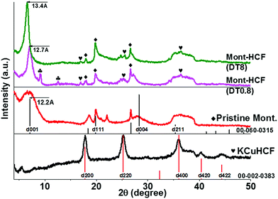
Powder X-ray diffraction (XRD) patterns of the Mont–HCF composites are shown in Fig. 2 and compared to pristine montmorillonite and KCuHCF as references. The pristine montmorillonite has a basal plane spacing (d001) of 1.22 nm, which is in good agreement with previously reported data.25 The d-spacing of the Mont–HCF composites expanded with increasing organic content to 1.27 nm and 1.34 nm for Mont–HCF(DT0.8) and Mont–HCF(DT8), respectively. The interlayer expansion suggests that the surfactant EH and ligand DT molecules are intercalated in the montmorillonite particles. The XRD patterns of the organo-clay–HCF composites, Mont–HCF(DT0.8) and Mont–HCF(DT8), have the characteristic diffraction peaks of montmorillonite, located at 2θ of 19.9° (111), 26.7° (103), 35.1° (211) (JCPDS card no. 60-0315), and additional peaks at 2θ values of 17.9°, 25.3° and 36.1°, which can be assigned to the (200), (220) and (400) planes of the cubic crystal structure of KCuHCF (with a cell constant of 9.99 Å; JCPDS card no. 02-0383). Thus, the XRD data confirms the presence of KCuHCF on the clay matrix. Moreover, the average crystallite size of the KCuHCF particles can be approximated using the Scherrer equation:
 | (2) |
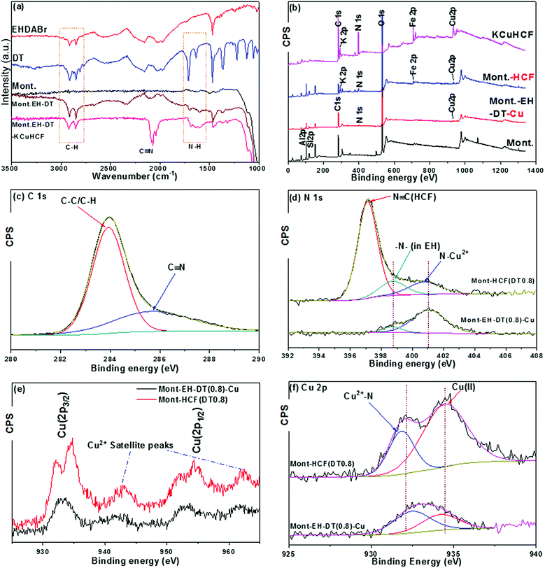
FTIR spectra were collected for the initial reactants EH, DT and pristine montmorillonite; intermediate products of step (i) the organo-clay (Mont–EH–DT); and the final product of step (iii) the Mont–HCF composite, and are shown in Fig. 3a (from top to bottom). For montmorillonite (Mont.) the strong broad adsorption band with a peak at ∼1000 cm−1 corresponds to the Si–O vibration of the tetrahedral silica sheet.27 In the sample of organo-clay (Mont–EH–DT), the C–H stretching vibration peaks between 2750 cm−1 and 3000 cm−1, and the CH2 bending vibration at 1470 cm−1 are assigned to the methylene moiety15,23 of the surfactant EH and the ligand DT, consistent with the reference spectra of EH and DT. In addition, the band in the range of 1620–1640 cm−1 is characteristic of the –NH bending of the amine groups10,15 originating here from DT, therefore confirming the successful preparation of organo-clays (Mont–EH–DT) in step (i). For the Mont–HCF composite (i.e. Mont–EH–DT–KCuHCF), when compared to the intermediate product Mont–EH–DT (step i), new peaks emerge at 2073 cm−1 and 2039 cm−1 and correspond to two closed CN stretching vibrations,16,18,28 thus indicating the formation of the ferrocyanide (HCF) structure, and verifying the completion of steps (ii) and (iii). As previously reported, these two peaks have been attributed to the stretching of the CN ligand bridged between Cu2+ and Fe2+ in two different modes.18 The success of step (ii) which features the copper–amine chelation is also demonstrated in the subsequent XPS analysis (Fig. 3b–f).
To further validate the success of the multi-step synthesis, XPS measurements on the intermediate product (step ii) of copper anchored organo-clay (Mont–EH–DT–Cu), and the final composite (step iii) of Mont–HCF were analysed using the sample Mont–HCF(DT0.8) as shown in Fig. 3b–f. Fig. 3b and d–f clearly show the presence of N 1s from DT/EH, and Cu 2p peaks in the sample of Mont–EH–DT–Cu. Although only weakly visible in Fig. 3b, these peaks are more pronounced in the high-resolution spectra shown in Fig. 3d and e. In particular, the peaks centred at 954 eV and 933 eV (Fig. 3e) were attributed to the Cu 2p1/2 and Cu 2p3/2 orbitals, respectively.29 These peaks, together with the characteristic satellite peaks of Cu2+ at 962 eV and 943 eV, confirm the presence of copper ions in the intermediate and final composites. In addition, the XPS spectrum of Mont–HCF (Fig. 3b) identifies the peaks of Fe (2p) and K (2p), which results from the in situ growth of HCF (as confirmed from the reference spectrum of pure KCuHCF shown in Fig. 3b). From the C 1s deconvolution spectrum in Fig. 3c, two peaks centered at 283.92 eV and 285.69 eV were identifiable, which corresponded to the matrix C–C/C–H peaks and a C![[triple bond, length as m-dash]](https://www.rsc.org/images/entities/char_e002.gif) N group respectively.28 In the N 1s spectra, the peak at 398.71 eV is characteristic of alkylammonium N, and the peak at 401.08 eV was assigned to the protonated amino group due to chelation with Cu2+ ions.30 These peaks were observed in both the Mont–EH–DT–Cu and the Mont–HCF. When compared to the intermediate of step (ii) (Mont–EH–DT–Cu), a new strong peak at 397.11 eV was observed in the Mont–HCF, signifying the existence of N
N group respectively.28 In the N 1s spectra, the peak at 398.71 eV is characteristic of alkylammonium N, and the peak at 401.08 eV was assigned to the protonated amino group due to chelation with Cu2+ ions.30 These peaks were observed in both the Mont–EH–DT–Cu and the Mont–HCF. When compared to the intermediate of step (ii) (Mont–EH–DT–Cu), a new strong peak at 397.11 eV was observed in the Mont–HCF, signifying the existence of N![[triple bond, length as m-dash]](https://www.rsc.org/images/entities/char_e002.gif) C ([Fe(CN)6]4−) in the composites. The XPS observations were consistent with the FTIR data shown in Fig. 3a. Moreover, the amino-copper chelation was confirmed from the Cu 2p3/2 spectrum in Fig. 3f, where peaks centered around 932.0 eV were evident (i.e. 932.46 eV for Mont–EH–DT–Cu and 931.82 eV for Mont–HCF). This response, which is characteristic of Cu+ species (∼932 eV), appears as a result of the redox reaction of the chelated Cu2+ with the amino groups.31 This peak becomes even more pronounced in the case of Mont–HCF when the ferrocyanide ([Fe(CN)6]4−) is immobilized with the C
C ([Fe(CN)6]4−) in the composites. The XPS observations were consistent with the FTIR data shown in Fig. 3a. Moreover, the amino-copper chelation was confirmed from the Cu 2p3/2 spectrum in Fig. 3f, where peaks centered around 932.0 eV were evident (i.e. 932.46 eV for Mont–EH–DT–Cu and 931.82 eV for Mont–HCF). This response, which is characteristic of Cu+ species (∼932 eV), appears as a result of the redox reaction of the chelated Cu2+ with the amino groups.31 This peak becomes even more pronounced in the case of Mont–HCF when the ferrocyanide ([Fe(CN)6]4−) is immobilized with the C![[triple bond, length as m-dash]](https://www.rsc.org/images/entities/char_e002.gif) N coordinating to the copper–DT complex.
N coordinating to the copper–DT complex.
From the FTIR and XPS analysis we can rationally conclude that Mont–HCF composites were successfully synthesized through the proposed copper–amine chelation mechanism. Depending on the amount of copper anchored by DT and subsequently reacted with an equivalent concentration of HCF precursor, the products of metal ferrocyanides prepared with different DT contents can be non-stoichiometric compounds. The relative atomic Cu/Fe ratios (Table S1 in ESI†) calculated from peak areas of the Cu 2p and Fe 2p peaks in the XPS spectra, were used to propose an ‘equivalent’ structure for the complex according to the model structure K2xCu(2−x)[Fe(CN)6].32 Such an approach is reasonable since Fe was not found on the surface of pristine montmorillonite (Table S1†), and can be considered to be a specific element originating from HCF. The measured compositions of the copper ferrocyanide immobilized on to the montmorillonite surface are presented in Table 1.
Fig. 4 shows SEM images of pristine montmorillonite and the as-prepared Mont–HCF composites (DT0.8 and DT8), plus the N to Si atomic ratios of these compounds as determined by EDX spectroscopy. The “plate-like” structure of pristine montmorillonite is clearly depicted in Fig. 4a. For Mont–HCF(DT0.8) (Fig. 4b), the silica basal plane becomes decorated with nano-sized particles, suggesting the presence of the KCuHCF nanoparticles on the montmorillonite surface. For Mont–HCF(DT8) (Fig. 4c), the inhomogeneous particle coverage appears to be replaced by a more uniform layer, forming a thin film and somewhat eliminating the sharp edge features of the pristine montmorillonite. The additional EDX data (Fig. 4d) shows that N, a characteristic element of DT and HCF, is detected in significant levels for both composite particles but not for the pristine montmorillonite. There is an incremental increase in N with nominal DT content (Fig. 4d). Both the SEM and EDX data further confirm the successful synthesis of organo-clay–KCuHCF composites.
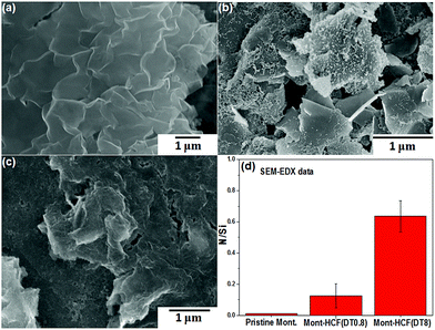 | ||
| Fig. 4 SEM images of (a) pristine montmorillonite, (b) Mont–HCF(DT0.8), (c) Mont–HCF(DT8) composites, and (d) N/Si ratio determined from SEM-EDX analysis. | ||
The structure of the composite adsorbents was further characterized by TEM. Fig. 5a–f show TEM images of Mont–HCF(DT0.8) and Mont–HCF(DT8) particles, respectively. The Mont–HCF(DT0.8) clay particles retain a plate-like structure of nanosheets, with the surface partially covered by nanoparticles (Fig. 5a and b); the nanoparticles were identified to be KCuHCF by the crystal lattice spacings (Fig. 5b). Moreover, by imaging the lattice fringe at the clay edges (Fig. 5c), it was possible to estimate the clay interlayer spacing, which in the current study was measured to be 1.41 nm, consistent with the expansion due to intercalated organics; typical interlayer spacing for pristine montmorillonite was found to be ∼1.0–1.2 nm.14,25
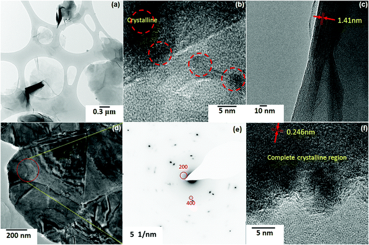 | ||
| Fig. 5 TEM images and electron diffraction pattern of composite adsorbents: (a–c) Mont–HCF(DT0.8); (d–f) Mont–HCF(DT8). | ||
The TEM analysis is qualitatively consistent with the XRD data (Fig. 2). As the DT concentration on the clay particles increased, more Cu was anchored and hence more KCuHCF nanoparticles and/or larger KCuHCF particles were formed. This was confirmed by the crystalline structures on the Mont–HCF(DT8), see Fig. 5d and f. The Si, C, and N mass fractions on the particle surface were measured by XPS (Table S1†), and show a general trend of decreasing Si and increasing C and N with increased DT concentration, thus validating the progressive coating of the clay particle surface by HCF nanoparticles. Fig. 5e shows a selected area electron diffraction (SAED) pattern taken from the highlighted region (red circle) in Fig. 5d. The SAED pattern for Mont–HCF(DT8) shows a strongly scattering clay lattice and weaker spots from the KCuHCF particles. Measurement of the latter leads to the labelled KCuHCF crystal, lattice planes (200) and (400) in Fig. 5e (JCPDS-ICDD no. 02-0383). In addition, lattice fringes of interplanar spacing of 0.246 nm were clearly visible in the high magnification TEM image (Fig. 5f), which corresponds to the (400) lattice plane of KCuHCF particles (JCPDS-ICDD no. 02-0383).
The organic content of the composite particles was determined by TGA, as shown in Fig. S2.† The pure organic components completely decomposed as the temperature increased from 200 to 400 °C. For pristine montmorillonite, a small but gradual weight loss is evident at ∼700 °C, and this can be attributed to the dihydroxylation of the aluminium-silicate layer and the decomposition of any existing carbonate.33,34 For pure KCuHCF, the first significant weight loss occurs in the range of 160 to 350 °C, which can be ascribed to both the elimination of coordinating water, this has been widely reported to exist in Prussian blue (PB)-like molecules (<250 °C),15,28 and also the decomposition of the cyano group which has been shown to occur in the range of 250 to 350 °C.15,35 At higher temperatures it is evident that the intermediate products undergo oxidative decomposition to iron oxides resulting in crystal growth, confirmed by the significant weight loss in the temperature range of 750–800 °C and the corresponding exothermic peak on the DSC curve (Fig. S2b†).36,37
For the organo-clays the thermal stability of the intercalated organics and the immobilized HCF was enhanced, as shown by the higher degradation temperatures across the temperature range 200 to 800 °C, with the two main weight losses observed around 400 °C and 600 °C. Considering the difference in mass loss between the intermediate organo-clay Mont–EH–DT and the final Mont–HCF composite product (Fig. S2c†), the mass fraction of KCuHCF nanoparticles in the composite particle can be estimated and is given in Table 1. Hence, a theoretical ion exchange capacity (TEC) can be calculated based on the potassium content of the immobilized HCF plus the maximum adsorption capacity (qm) of the organo-clay matrix.
3.2 Batch adsorption experiments
 | (3) |
| Sample | Langmuir | Dual-site Langmuir | ||||||
|---|---|---|---|---|---|---|---|---|
| q m mg g−1 | b L mg−1 | R 2 | q m1 mg g−1 | b 1 L mg−1 | q m2 mg g−1 | b 2 L mg−1 | R 2 | |
| Pristine Mont. | 103.00 | 0.005 | 0.91 | |||||
| Mont–HCF(DT0.1) | 206.64 | 0.188 | 0.94 | 70.02 | 0.019 | 144.09 | 0.019 | 0.95 |
| Mont–HCF(DT0.8) | 173.05 | 0.109 | 0.91 | 60.79 | 0.003 | 131.68 | 0.027 | 0.98 |
| Mont–HCF(DT8) | 139.29 | 0.020 | 0.93 | |||||
| Mont–HCF(DT50) | 153.09 | 0.030 | 0.90 | |||||
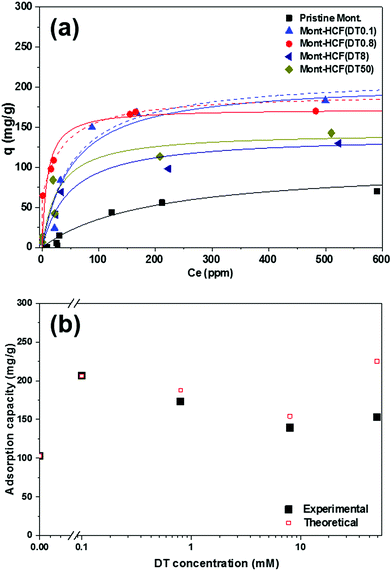
It is worth noting that the apparent poor performance of the Mont–HCF composites with higher DT contents (i.e. DT8, DT50), as shown in Fig. 6b, resulted from a reduction in the adsorption capacity (CEC) of the clay matrix, brought about by the increased intercalation of DT. The reduced CEC with high DT concentration (i.e. DT8, DT50) was confirmed by measuring the Cs+ adsorption capacity of the organo-clay intermediates prior to HCF anchoring, which gave negligible values (qm ∼ 0 mg g−1) as shown in the ESI Fig. S3.† For the Mont–HCF composite adsorbents, a theoretical ion-exchange capacity (TEC) can be calculated based on the potassium content of the immobilized HCF and the experimentally measured qm of the organo-clay matrix.
Since both parameters (HCF content, qm of organo-clay matrix) vary for each composite, the TEC was calculated between 154 and 225 mg g−1 for increasing DT concentration (see Table 1). As shown in Fig. 6b, the TEC is in reasonable agreement with the experimentally determined maximum adsorption capacities (qm). The fluctuating performance of the organo-clay–HCF composites (i.e. maximum qm at DT = 0.1 mM and minimum qm at DT 0.8 mM) can be attributed to the relative ion exchange capacities of both media (organo-clay and HCF content). At low DT concentrations (DT ≤ 0.8 mM) both the clay and bound HCF particles are active ion exchange sites, but with increasing DT concentration the organo-clay ion exchange capacity decreases (Table 1) and the HCF ion exchange capacity increases (directly related to the HCF content). Hence, the overall ion exchange capacity is a function of the relative contributions from both ion exchange sites. At higher DT concentrations the ion-exchange capacity of the organo-clay is effectively zero (Fig. S3†), hence qm becomes a function of the HCF content only.
Such dependence has been validated by EDX mapping of the composite particles (see ESI Fig. S5†), where both the Cs and Fe peak intensities were higher for Mont–HCF(DT50) compared to Mont–HCF(DT8), confirming higher Cs+ adsorption when the HCF concentration was higher. Likewise from XPS analysis, the higher Cs/Si ratio (Fig. S4†) for Mont–HCF(DT50) than Mont–HCF(DT8) and Mont–HCF(DT0.8) further supports this conclusion. Based on the TEC data we should observe a 25% increase in qm between Mont–HCF(DT0.1) and Mont–HCF(DT50). While this enhancement demonstrates the added capacity through incorporation of more HCF, the practicality of using Mont–HCF(DT50) particles is limited by the presence of many unbound HCF nanoparticles which results from HCF saturation of the clay matrix. Any unbound HCF particles remaining in the suspension (even though the particle suspension was washed several times), will result in an overestimation of Cs+ in the supernatant as measured by AAS (equivalent to an underestimation of Cs+ adsorption), thus contributing to the deviation between theory and experiment for Mont–HCF(DT50) particles. Such difficulties associated with the removal of unbound HCF particles has been reported.15
In light of the fact that the Mont–HCF composites with DT0.1 and DT0.8 contain two possible active sites for ion sorption, the montmorillonite particle and the immobilized HCF, the dual-site Langmuir adsorption model was also considered, and describes sorption at two sites of different sorption energies. The dual-site Langmuir equation is given by:
 | (4) |
XPS spectra of the organo-clay–HCF composite particles saturated with Cs+ (C0 = 5 mM) confirmed the significant displacement of K+ by Cs+, see Fig. S4.† Following Cs+ adsorption the XRD data shown in Fig. 7 confirmed a reduction in the KCuHCF(200) peak height at 17.9° and a shift of the (220) and (400) planes to lower 2θ around 24.8° and 34.3°, confirming an effective crystal phase transition from KCuHCF to CsCuHCF (JCPDS card no. 24-0248). The XRD data suggest that the immobilized KCuHCF complex greatly contributes to Cs+ adsorption via an ion-exchange mechanism, with these findings supported by the XPS data. In addition, a decrease in the clay (Mont–HCF(DT0.8)) d-spacing (d001) from 1.27 nm to 1.22 nm implies that Cs+ adsorption also occurred via isomorphic ion-substitution, leading to a slight reduction in the clay interlayer spacing, mainly due to the unfavourable hydration of the Cs+ existing in the interlayer.38
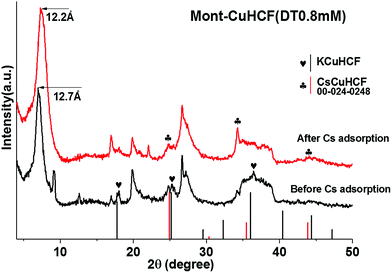 | ||
| Fig. 7 XRD patterns of Mont–HCF(DT0.8) before and after Cs+ adsorption (pattern file 00-024-0248 for CsCuHCF). | ||
When compared to other clay-based adsorbents and KCuHCF adsorbents immobilized onto a range of different supporting materials, the Mont–HCF composites prepared in the current study are shown to be some of the most effective Cs+ adsorbents in terms of qm. Adsorption capacity data from a number of studies has been compared to Mont–HCF(DT0.1) and are shown in Table 3.
| Clay/Co-metal in HCF | Modifier/support | q m (mgCs g−1 composite) | Reference/publication year |
|---|---|---|---|
| a Maximum adsorption capacity determined from Langmuir model. b The relatively wide range depends on the CEC of the specific type of montmorillonite. | |||
| Clay | |||
| Montmorillonite | Pristine | 57–104b | 10–12 and 38/2013, 2011, 2002, 2009 |
| Montmorillonite | Aluminum-pillared | 83 | 39/2007 |
| Montmorillonite | Phosphate | 94 | 11/2011 |
| Montmorillonite | Ethylamine | 80 | 10/2013 |
| Montmorillonite | Manganese oxide | 90 | 40/2012 |
| Montmorillonite | CuHCF(DT0.1) | 206 | Current study |
![[thin space (1/6-em)]](https://www.rsc.org/images/entities/char_2009.gif) |
|||
| Co-Metal in HCF | |||
| Cu | Activated carbon | 6 | 41/2009 |
| Cu | Polyacrylonitrile (PAN) | 26 | 42/2011 |
| Cu | Chitin | 118 | 15/2014 |
| Cu | Mesoporous silica | 177 | 19/2001 |
| Cu | Montmorillonite(DT0.1) | 206 | Current study |
 | (5) |
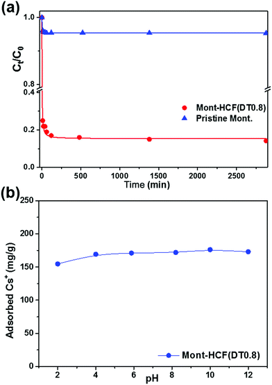 | ||
| Fig. 8 (a) Cs+ uptake kinetics for organo-clay–HCF composites, and pristine montmorillonite (C0 = 1 mM). (b) Cs+ adsorption as a function of the solution pH (C0 = 5 mM). | ||
| Sample | k 2 (g mg−1 min−1) | Q e (mg g−1) | R 2 |
|---|---|---|---|
| Pristine Mont. | 0.09816 | 5.31 | 0.99 |
| Mont–HCF(DT0.8) | 0.00695 | 92.72 | 0.99 |
 | (6) |
Moreover, the effect of DT content on the Cs+ selectivity has been examined and was shown to be insignificant (data not shown), with Kd values within 2% over the DT concentration range studied.
3.3 Flotation selectivity
One of the objectives of this study was to synthesize organo-clays that exhibit high Cs+ removal performance and can be easily recovered from the aqueous environment by flotation. Flotation performance of the Cs-loaded particles was studied using a laboratory flotation cell, as shown in Fig. S1 of the ESI.† The particle (mass) recovery percentage (R%) and the particle contact angle are shown in Fig. 9.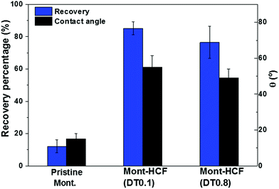 | ||
| Fig. 9 Flotation recovery percentages of Cs-loaded particles (C0 = 5 mM). The associated particle contact angles approximated by the sessile drop technique are shown on the second y-axis. | ||
The flotation experiments were completed in the absence of any collector, i.e. collector-less flotation. As shown in Fig. 9, the recovery performance of the Cs-loaded montmorillonite was very poor, less than 15%, in comparison to the Cs-loaded Mont–HCF composite (Mont–HCF(0.1)), which has a recovery efficiency in the range of 80–90%. This significant difference can be attributed to an increase in the particle hydrophobicity induced via the interlayer intercalation and surface decoration of the clay particles by the organic components of EH and DT. This is also consistent with the measured contact angle data (Fig. 9) and the slight reduction in the particle zeta potential when the DT content increases (Table 5). These modifications to the particle surface properties promote slight aggregation of the composite particles and a broadening of the particle size distribution which may also contribute to the enhanced flotation performance, see Fig. S6 in the ESI.†
Together with the qm data presented in Fig. 6, it is reasonable to conclude that the as-prepared Mont–HCF based composite particles demonstrate both high Cs+ uptake and selectivity, along with excellent recovery by collector-less flotation. This approach provides a cost-effective route to treat large volumes of aqueous wastes, reducing the environmental contamination, and minimizing the volume of waste for further treatment and ultimate disposal.
4. Conclusions
A low cost and facile synthesis route has been demonstrated for organo-clay–HCF composites. The particle synthesis route included (i) organic modification of montmorillonite with cationic surfactant (EH) and alkyldiamine (DT), (ii) copper chelation with the anchored DT, and (iii) growth of Cu2+/[Fe(CN)6]4−/2K+ nanoparticles (KCuHCF) via the coordination between hexacyanoferrate precursors and the immobilized copper ions. XRD analysis confirmed the expansion of the clay interlayer due to adsorption of organics, along with identifying the crystal structure of KCuHCF nanoparticles. FTIR analysis confirmed the formation of CN bonds in the composite adsorbents implying the successful immobilization of HCF on the clay, which was further supported by EDX and XPS analysis. XPS also demonstrated that the KCuHCF immobilization was realized via a copper–amine coordination mechanism. SEM and TEM confirmed the decoration of the clay particles with sub 15 nm KCuHCF particles.The DT concentration was varied between 0.1 mM and 50 mM, with increasing DT concentration resulting in the formation of more KCuHCF nanoparticles. However, at DT concentrations greater than 0.8 mM, a significant excess of KCuHCF nanoparticles were produced that were not well attached to the clay particles. These unbound particles were mostly unrecoverable following a series of sample washes, leading to apparent errors in the Cs+ adsorption experiments when measured by Atomic Adsorption Spectrophotometry. Such production of unbound KCuHCF nanoparticles prohibited the use of Mont–HCF(DT8) and Mont–HCF–(DT50) composite adsorbents. For Mont–HCF(DT0.1) the Cs+ adsorption capacity (qm) was shown to be 206 mg g−1, which was double the qm for pristine montmorillonite particles. The excellent Cs+ adsorption performance of the Mont–HCF composite was demonstrated over a wide pH range, as well as in seawater where the adsorption selectivity for Cs+ in a complex solution of competing cations was shown to be superior compared to pristine montmorillonite, validating the robustness of the composite adsorbent.
The novel synthesis route not only enhanced the Cs+ adsorption capacity of montmorillonite, but also increased the particle hydrophobicity. This effect allowed the Cs-loaded composite particles to be easily recovered by flotation, without the need for addition of flotation collectors. For the composite adsorbent, recovery efficiency was in the range of 80 to 90%, compared to less than 15% for Cs-loaded pristine montmorillonite.
The current study has demonstrated a new concept for Cs+ removal from aqueous environments. Rather than filtration through packed-bed columns, where blockages and chemical incompatibility can hinder performance, the novel approach to clean-up relies on the recovery of Cs-loaded clay particles by flotation, a technique that is suitable for remote deployment on any scale, facilitating the decontamination of environments, and minimizing the volume of waste for ultimate disposal.
Acknowledgements
This work was financially supported by the Engineering and Physical Sciences Research Council (EPSRC) (grant number EP/M026426/1) and the National Research Foundation of Korea (NRF) (grant number NRF-2015M2A7A1000219). X-ray Photoelectron Spectroscopy was conducted at the National EPSRC XPS User's Service (NEXUS) at Newcastle University, an EPSRC mid-range facility. H. Z. acknowledges Mr Thomas Howell and Dr Jabbar Gardy for their kind technical assistance on TGA/FTIR and XRD, respectively.Notes and references
- D. H. Ding, Z. Y. Zhang, Z. F. Lei, Y. N. Yang and T. M. Cai, Environ. Sci. Pollut. Res., 2016, 23, 2249–2263 CrossRef CAS PubMed.
- J. L. Mertz, Z. H. Fard, C. D. Malliakas, M. J. Manos and M. G. Kanatzidis, Chem. Mater., 2013, 25, 2116–2127 CrossRef CAS.
- M. A. Olatunji, M. U. Khandaker, H. N. M. E. Mahmud and Y. M. Amin, RSC Adv., 2015, 5, 71658–71683 RSC.
- S. Komarneni and R. Roy, Science, 1988, 239, 1286–1288 CAS.
- A. J. Celestian, J. D. Kubicki, J. Hanson, A. Clearfield and J. B. Parise, J. Am. Chem. Soc., 2008, 130, 11689–11694 CrossRef CAS PubMed.
- H. M. Liu, A. Yonezawa, K. Kumagai, M. Sano and T. Miyake, J. Mater. Chem. A, 2015, 3, 1562–1568 CAS.
- S. J. Datta, W. K. Moon, D. Y. Choi, I. C. Hwang and K. B. Yoon, Angew. Chem., Int. Ed., 2014, 53, 7203–7208 CrossRef CAS PubMed.
- N. Ding and M. G. Kanatzidis, Nat. Chem., 2010, 2, 187–191 CrossRef CAS PubMed.
- X. H. Qi, K. Z. Du, M. L. Feng, J. R. Li, C. F. Du, B. Zhang and X. Y. Huang, J. Mater. Chem. A, 2015, 3, 5665–5673 CAS.
- H. Long, P. X. Wu and N. W. Zhu, Chem. Eng. J., 2013, 225, 237–244 CrossRef CAS.
- B. Ma, S. Oh, W. S. Shin and S. J. Choi, Desalination, 2011, 276, 336–346 CrossRef CAS.
- B. C. Bostick, M. A. Vairavamurthy, K. G. Karthikeyan and J. Chorover, Environ. Sci. Technol., 2002, 36, 2670–2676 CrossRef CAS PubMed.
- J. Q. Jiang and Z. Q. Zeng, Chemosphere, 2003, 53, 53–62 CrossRef CAS PubMed.
- T. H. Wang, C. J. Hsieh, S. M. Lin, D. C. Wu, M. H. Li and S. P. Teng, Environ. Sci. Technol., 2010, 44, 5142–5147 CrossRef CAS PubMed.
- T. Vincent, C. Vincent, Y. Barre, Y. Guari, G. Le Saout and E. Guibal, J. Mater. Chem. A, 2014, 2, 10007–10021 CAS.
- Y. Kim, Y. K. Kim, S. Kim, D. Harbottle and J. W. Lee, Chem. Eng. J., 2017, 313, 1042–1050 CrossRef CAS.
- C. Loos-Neskovic, S. Ayrault, V. Badillo, B. Jimenez, E. Garnier, M. Fedoroff, D. J. Jones and B. Merinov, J. Solid State Chem., 2004, 177, 1817–1828 CrossRef CAS.
- R. Turgis, G. Arrachart, C. Delchet, C. Rey, Y. Barre, S. Pellet-Rostaing, Y. Guari, J. Larionova and A. Grandjean, Chem. Mater., 2013, 25, 4447–4453 CrossRef CAS.
- Y. H. Lin, G. E. Fryxell, H. Wu and M. Engelhard, Environ. Sci. Technol., 2001, 35, 3962–3966 CrossRef CAS PubMed.
- V. V. Strelko, V. K. Mardanenko, V. V. Yatsenko and N. Patrilyak, Russ. J. Appl. Chem., 1998, 71, 1746–1749 Search PubMed.
- M. Honty, M. De Craen, L. Wang, J. Madejova, A. Czimerova, M. Pentrak, I. Stricek and M. Van Geet, Appl. Geochem., 2010, 25, 825–840 CrossRef CAS.
- D. G. Devivo and B. L. Karger, Sep. Sci., 1970, 5, 145–167 CAS.
- P. Malakul, K. R. Srinivasan and H. Y. Wang, Ind. Eng. Chem. Res., 1998, 37, 4296–4301 CrossRef CAS.
- J. Chorover, S. K. Choi, M. K. Amistadi, K. G. Karthikeyan, G. Crosson and K. T. Mueller, Environ. Sci. Technol., 2003, 37, 2200–2208 CrossRef CAS PubMed.
- C. W. Chiu and J. J. Lin, Prog. Polym. Sci., 2012, 37, 406–444 CrossRef CAS.
- M. S. Cavalcante, S. P. A. Paz, R. S. Angelica, E. N. Ito and R. F. Neves, Clay Miner., 2016, 51, 39–54 CrossRef CAS.
- J. Madejova, Vib. Spectrosc., 2003, 31, 1–10 CrossRef CAS.
- H. J. Yang, L. Sun, J. L. Zhai, H. Y. Li, Y. Zhao and H. W. Yu, J. Mater. Chem. A, 2014, 2, 326–332 CAS.
- Z. Y. Liu, Y. X. Hu, C. F. Liu and Z. Y. Zhou, Chem. Commun., 2016, 52, 12245–12248 RSC.
- M. E. A. Ali, F. M. Hassan and X. S. Feng, J. Mater. Chem. A, 2016, 4, 6620–6629 CAS.
- L. Y. Chai, T. Wang, L. Y. Zhang, H. Y. Wang, W. C. Yang, S. Dai, Y. Meng and X. R. Li, Carbon, 2015, 81, 748–757 CrossRef CAS.
- C. Loosneskovic, M. Fedoroff, E. Garnier and P. Gravereau, Talanta, 1984, 31, 1133–1147 CrossRef CAS.
- L. Cabedo, D. Plackett, E. Gimenez and J. M. Lagaron, J. Appl. Polym. Sci., 2009, 112, 3669–3676 CrossRef CAS.
- D. Eliche-Quesada, C. Martinez-Garcia, M. L. Martinez-Cartas, M. T. Cotes-Palomino, L. Perez-Villarejo, N. Cruz-Perez and F. A. Corpas-Iglesias, Appl. Clay Sci., 2011, 52, 270–276 CrossRef CAS.
- J. H. Her, P. W. Stephens, C. M. Kareis, J. G. Moore, K. S. Min, J. W. Park, G. Bali, B. S. Kennon and J. S. Miller, Inorg. Chem., 2010, 49, 1524–1534 CrossRef CAS PubMed.
- Z. F. Jiang, D. L. Jiang, A. M. S. Hossain, K. Qian and J. M. Xie, Phys. Chem. Chem. Phys., 2015, 17, 2550–2559 RSC.
- Q. F. Wu, G. L. Wu, L. D. Wang, W. L. Hu and H. J. Wu, Mater. Sci. Semicond. Process., 2015, 30, 476–481 CrossRef CAS.
- J. J. Wu, B. Li, J. L. Liao, Y. Feng, D. Zhang, J. Zhao, W. Wen, Y. Y. Yang and N. Liu, J. Environ. Radioact., 2009, 100, 914–920 CrossRef CAS PubMed.
- D. Karamanis and P. A. Assimakopoulos, Water Res., 2007, 41, 1897–1906 CrossRef CAS PubMed.
- Y. Park, W. S. Shin and S. J. Choi, J. Radioanal. Nucl. Chem., 2012, 292, 837–852 CrossRef CAS.
- L. Wang, M. Feng, C. X. Liu, Y. S. Zhao, S. Q. Li, H. Wang, L. Yan, G. Tian and S. J. Li, Sep. Sci. Technol., 2009, 44, 4023–4035 CrossRef CAS.
- A. Nilchi, R. Saberi, M. Moradi, H. Azizpour and R. Zarghami, Chem. Eng. J., 2011, 172, 572–580 CrossRef CAS.
- S. B. Yang, N. Okada and M. Nagatsu, J. Hazard. Mater., 2016, 301, 8–16 CrossRef CAS PubMed.
Footnote |
| † Electronic supplementary information (ESI) available. See DOI: 10.1039/c7ta03873a |
| This journal is © The Royal Society of Chemistry 2017 |

