 Open Access Article
Creative Commons Attribution 3.0 Unported Licence
MgFeSiO4 as a potential cathode material for magnesium batteries: ion diffusion rates and voltage trends†
Jennifer
Heath
,
Hungru
Chen
and
M. Saiful
Islam
 *
*
Department of Chemistry, University of Bath, Bath, BA2 7AY, UK. E-mail: m.s.islam@bath.ac.uk
First published on 31st May 2017
Abstract
Developing rechargeable magnesium batteries has become an area of growing interest as an alternative to lithium-ion batteries largely due to their potential to offer increased energy density from the divalent charge of the Mg ion. Unlike the lithium silicates for Li-ion batteries, MgFeSiO4 can adopt the olivine structure as observed for LiFePO4. Here we combine advanced modelling techniques based on energy minimization, molecular dynamics (MD) and density functional theory to explore the Mg-ion conduction, doping and voltage behaviour of MgFeSiO4. The Mg-ion migration activation energy is relatively low for a Mg-based cathode, and MD simulations predict a diffusion coefficient (DMg) of 10−9 cm2 s−1, which suggest favourable electrode kinetics. Partial substitution of Fe by Co or Mn could increase the cell voltage from 2.3 V vs. Mg/Mg2+ to 2.8–3.0 V. The new fundamental insights presented here should stimulate further work on low-cost silicate cathodes for Mg batteries.
1. Introduction
The Li-ion battery currently dominates the portable energy storage market, powering mobile phones, laptop computers and electric vehicles. But the next generation of electronics will rapidly overtake the limit of what is theoretically possible with traditional Li-ion systems. While there are new approaches, such as the development of Na-ion batteries and solid-state Li-ion batteries, that could potentially offer cost, specific energy and safety advantages, there are few options to improve energy density. One strategy to improve energy density beyond the capability of Li+ systems is to utilise multivalent cations, specifically the Mg2+ ion, owing to its similar size to Li+.1–6 Improvements in energy density originate from the ability to use a metal anode rather than an insertion structure. In addition, dendrite formation, which prevents the use of Li metal anodes for Li-ion batteries, does not occur with Mg metal anodes.2Due to the difficulty of Mg2+ insertion/extraction in host structures, the choice of cathode materials for Mg batteries is limited. This is thought to be due to stronger ionic interactions and harder charge redistribution of Mg2+ ions in comparison to Li+ ions.3 Approaches used to improve the diffusivity of Mg2+ ions in cathode materials have included decreasing the particle size of the cathode,7 charge shielding of the inserted Mg2+ ions8,9 and redistribution of the electrons donated by Mg to transition metal clusters.3,10–12
Various potential cathode materials for Mg batteries have been considered, such as V2O5,13–17 polymorphs of MnO2,18–24 molybdenum chalcogenides,1,3,25 and spinel sulphides and oxides.26–29 Recently, olivine-type Mg silicates have been reported to show promising cathode performance for Mg batteries, with some indication of reversible Mg intercalation.30–36 This follows extensive work on lithium-based silicates, Li2FeSiO4 and Li2MnSiO4, as possible low-cost and stable cathodes due to the high natural abundance of silicon and the strong Si–O bonds.37
It has previously been reported that the olivine phase of MgFeSiO4 exhibits a degree of mixing between octahedral Mg and Fe crystallographic sites.38–40 However, ordered phases of the MgFeSiO4 structure have been synthesised through high temperature methods. A synthesis temperature of up to approximately 900 °C yields a structure where Mg2+ occupies M2 octahedral sites and Fe2+ prefers M1 octahedral sites. However above this temperature, the site preference switches, with Mg2+ and Fe2+ residing in M1 and M2 positions, respectively.38 Therefore, above 900 °C MgFeSiO4 can be synthesised with a structure analogous to LiFePO4, where the Mg2+ ions form one-dimensional channels along the c-axis.
In previous studies, Mg2+ has been inserted into disordered olivine FePO4 with a measured capacity of only ∼13 mA h g−1. This poor performance was found to be linked to surface amorphisation that prevented the electrochemical reaction from penetrating the bulk, rather than poor Mg2+ mobility in the structure.41 A first-principles study on the magnesium silicates reports the redox and thermodynamic behaviour of these compounds,33 revealing a similarity between lithium- and magnesium-insertion processes. However, these calculations did not consider kinetic processes, such as the transport of Mg2+ ions in the host lattice, which are essential to the performance of ion intercalation electrodes.
It is well established that the underlying transport and electronic properties of battery cathode materials are crucial to the greater understanding of their electrochemistry, but are not fully characterised for MgFeSiO4. Here we investigate the solid-state features that influence the electrochemical performance of ordered MgFeSiO4 (with a structure analogous to olivine LiFePO4), by employing advanced modelling methods to probe the Mg-ion transport properties and voltage trends from transition metal doping.
2. Methods
The methods used here are well established and detailed elsewhere.42,43 Previous studies on inorganic solids have successfully applied these potential-based methods, including olivine-structured LiFePO4 and NaFePO4 (ref. 44–46) and Li and Na silicate cathode materials.47–50 Interactions between ions in the silicate framework were described using the Born-model framework, with a long-range coulombic term and a short-range term to model electron–electron repulsions and van der Waals interactions. The inclusion of a three-body term was necessary in order to model the angle-dependent nature of the SiO4 unit.47 The shell model51 was used to account for the ionic polarisability effects. The interatomic potentials used here (listed in Table S1 in ESI†) were taken from previous studies on related oxides and silicates.47,49,52 The Mott–Littleton approach is used to simulate the lattice relaxation around defects and migrating ions, which is incorporated within the GULP code.53Molecular dynamics (MD) calculations, which introduce kinetic energy to the system by solving Newton's equations of motion for an ensemble of ions at finite temperatures, were performed using the LAMMPS code.54 The calculations were carried out on a simulation box, with periodic boundary conditions, made up of 12 × 6 × 10 unit cells, consisting of 20 160 atoms. The initial configuration of the structure contained 10% Mg vacancies (and corresponding Fe3+ species), which were randomly distributed. The Pedone model55 was used for the MD simulations, which was employed successfully in recent studies on Na-ion conducting battery materials.50,56 Three initial configurations were investigated and the results of the three structures were averaged. Simulation runs were carried out using the NVT ensemble and a time step of 2 fs for long runs of 6 ns, at temperatures in the range 300–1500 K. Pre-equilibrium runs of 4 ps with NVE and NPT ensembles were first used for stable configurations. Computer simulations have been used to investigate a range of materials for lithium and sodium batteries.40,42,56–59
Density functional theory (DFT) calculations were performed using a plane wave basis set implemented in the VASP code.60 A cutoff energy of 440 eV and k-point mesh of 2 × 4 × 5 were needed to converge the forces and energies. PAW potentials61,62 and the spin-polarized generalised gradient approximation (GGA) with the PBEsol functional63 were used. DFT+U methodology was used to account for the metal d-orbitals with an effective Hubbard Ueff = U − J = 4.3, 3.9, 3.3 and 6.0 eV (J = 1.0 eV) for Fe, Mn, Co and Ni, respectively.56 A ferromagnetic arrangement of the unpaired 3d electrons was assumed. The Mg2+/Mg cell voltage for the Fe2+/Fe3+ redox couple was calculated using the following equation:
 | (1) |
The chemical potential of magnesium (μ{Mg}) was calculated using Mg metal. Such DFT techniques have been applied to other battery materials29,42,57,59 including Li-ion silicate cathodes.58,64
3. Results and discussion
3.1 Structural modelling
The olivine-type structure of the cation-ordered MgFeSiO4 belongs to the Pmnb space group (Fig. 1),34 and consists of corner sharing FeO6 octahedra along the bc plane. SiO4 tetrahedra share corners and edges with the FeO6 octahedra. Mg ions are located in channels along the c-axis. The starting point of the study was to reproduce the experimentally observed structure of MgFeSiO4. A comparison between the calculated unit cell parameters based on effective potentials and those of the experimental structures is given in Table 1 (and further details on potential models are given in Table S2†).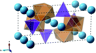 | ||
| Fig. 1 Olivine-type structure of MgFeSiO4 (orange octahedra: FeO6, purple tetrahedra: SiO4, light blue spheres: Mg2+ ions). | ||
| Parameter | Experimental38 (Å) | Calculated (Å) | Δ (Å) |
|---|---|---|---|
| a | 4.807 | 4.854 | 0.047 |
| b | 10.376 | 10.336 | −0.040 |
| c | 6.061 | 6.026 | −0.035 |
| Mg–O | 2.168 | 2.131 | −0.037 |
| Fe–O | 2.125 | 2.140 | 0.015 |
| Si–O | 1.624 | 1.639 | 0.015 |
The lattice parameters were computed to within 1% of the experimental values. Reproduction of the lattice parameters adds validity to the interatomic model used for simulating defects and Mg-ion migration.
3.2 Energetics and pathways for Na-ion migration
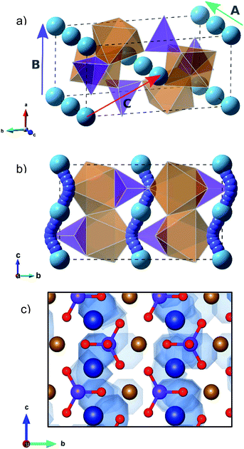
Examination of the intrinsic Mg-ion mobility in MgFeSiO4 is of interest when considering its use as a cathode material for magnesium batteries. In the olivine structure there are three potential pathways for Mg-ion migration, as shown in Fig. 2a. The activation energies of Mg migration along these pathways in MgFeSiO4 are listed in Table 2, along with the Mg–Mg distances. The activation energy is significantly lower for pathway A (parallel to the c-axis) than for pathways B and C. This is similar to the results obtained for olivine LiFePO4,44 where the lowest energy pathway is along open channels that run parallel to the b-axis. The activation energies for pathways B and C are both prohibitively high and so Mg ion migration is not likely in these directions. This can be rationalised by considering the structure of MgFeSiO4; the distance between neighbouring Mg2+ ions in pathways B and C is greater than pathway A. In addition, pathway B has a smaller channel size than pathway A. Pathway C would involve migration directly past both Fe–O and Si–O bonds, both of which would contribute to the high migration energy found.| Pathway | Mg–Mg distance (Å) | E a Mg (eV) |
|---|---|---|
| A | 3.01 | 0.60 |
| B | 4.85 | 5.18 |
| C | 5.71 | 5.43 |
Fig. 2b shows the curved pathways along which Mg-ion migration is predicted to take place in MgFeSiO4. These same migration pathways have also been simulated in olivine LiFePO4,44 and subsequently confirmed by diffraction measurements and maximum entropy studies.65 The calculated migration energy for this pathway was 0.60 eV, just 0.05 eV higher than that calculated for LiFePO4.44
A previous first-principles study carried out by Rong et al.66 reports the migration energies of different multivalent ions in olivine FePO4, layered NiO2 and spinel Mn2O4. Here Mg2+ diffusion in the olivine structure was calculated to require approximately 0.7 eV, lower than multivalent cation diffusion in the layered and spinel structures, calculated at approximately 1.1 and 0.8 eV, respectively. The relativity low migration energies predicted for both olivine FePO4 and MgFeSiO4 suggest favourable Mg2+ ion transport in the olivine structure.
MD techniques, used here at long timescales, are well suited to examine ion motion. The curved pathways predicted using energy minimisation techniques were also generated using MD, as shown in the energy density plot in Fig. 2c.
A small degree of anti-site defects (the exchange of Mg2+/Fe2+ on neighboring sites) is found in the MD calculations; an example can be seen in Fig. 2c, where Mg-ion density is found near the Fe sites. These defects were anticipated given the high levels of Mg/Fe mixing in the thermodynamically stable form of MgFeSiO4.38–40 This type of defect has been reported to cause blocking of the 1D migration pathways in olivine LiFePO4.67 However, major blocking of the Mg channels was not observed in our MD simulations, which is likely to be important for reversible Mg intercalation. Hence, we predict that while anti-site defects may form causing a localised blocking effect, the Fe2+ ions are able to migrate back into their original sites allowing Mg2+ ions to diffuse through uninterrupted channels. Also there was no evidence of inter-channel hopping of the displaced Mg2+ ions.
The mean squared displacement (MSD) of Mg ions, [r(t)]2, for MgFeSiO4 is shown in Fig. 3. The MSD data can be used to derive the Mg-ion diffusion coefficient (DMg) using:
 | (2) |
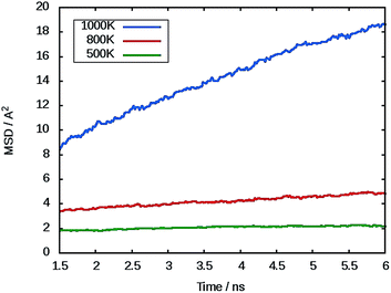 | ||
| Fig. 3 Representative mean squared displacement (MSD) data for magnesium ions in MgFeSiO4 at 500 K (green), 800 K (red) and 1000 K (blue). | ||
At 300 K a DMg value of 1.1 × 10⁻⁹ cm2 s−1 was calculated. To our knowledge there no experimental or calculated diffusion coefficients for ordered MgFeSiO4 for direct comparison. A previous study on tavorite FeSO4F as a potential cathode for Mg batteries, quoted an estimated DMg in the range of 10−9 cm2 s−1, the same order of magnitude as observed for Li diffusion in the same structure.68 Interestingly, Mg batteries may be more suitable for high temperature environments where the diffusion rate (and electrode kinetics) would be higher.
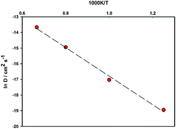
An Arrhenius plot for Mg2+ diffusion in MgFeSiO4 is shown in Fig. 4, which can be used to estimate the activation energy of migration. An activation energy of 0.79 eV was derived. While this value is slightly higher than that predicted using energy minimisation, it is still relatively low for a Mg-based cathode material. This result and the prediction of DMg in the range of Li-ion cathode materials, suggests favourable Mg2+ intercalation kinetics for ordered MgFeSiO4.
3.3 Dopant substitution
Previous dopant studies on lithium-ion battery cathodes have suggested that the incorporation of dopants on certain sites could potentially improve the capacity of the material by increasing the amount of lithium available for extraction through formation of lithium interstitial defects.47 Doping strategies could also be beneficial for magnesium-ion cathode materials. While the divalent nature of the magnesium ion offers increased energy density over monovalent lithium, many structures only allow for the de/intercalation of half of the available magnesium. The incorporation of dopants could create Mg interstitial defects that could consequently improve the capacity of the cathode material.Here we investigate trivalent doping (Al, Ga and V) on the Si site within the MgFeSiO4 structure. The doping process is described using the following equation (where M = Al, Ga or V):
 | (3) |
M3+ doping on the Si site is charge compensated by the formation of an Mg interstitial. We note that the alternative charge-compensation mechanism involving oxygen vacancies is less favourable by more than 4 eV. Trivalent doping on other sites in the structure would yield Fe vacancy as compensation, which would not improve the capacity or Mg diffusion in the material.
The dopant substitution reaction energies were calculated by combining the appropriate defect and lattice energy terms, listed in Table 3. Interatomic potentials used to model the corresponding binary oxides of the dopant cations were used in each case (Table S3†). This systematic approach to dopant incorporation has been applied successfully to other silicate systems.47
| Dopant | Energy (eV) |
|---|---|
| Al3+ | 5.64 |
| Ga3+ | 8.99 |
| V3+ | 8.59 |
The large incorporation energies (in Table 3) for trivalent Al, Ga and V doping in MgFeSiO4 to create Mg interstitials are unfavourable, and suggest a low degree of dopant solubility. Therefore, we conclude such trivalent doping of MgFeSiO4 is not a viable method to improve its capacity or Mg diffusion properties.
3.4 Cell voltage trends
One challenge to overcome when developing new cathode materials for magnesium-ion batteries is to establish an adequate operating voltage (in the range of approximately 2.0–3.0 V) while simultaneously retaining a high reversible capacity.69,70 V2O5 is reported to have a voltage of 2.66 V when paired with Mg/Mg2+, within the appropriate range. However, as a cathode material it suffers from slow magnesium diffusion.71 Other potential cathode materials for Mg batteries have displayed voltages much lower than the optimal window, such as the Chevrel phase Mo6S8 and spinel MgTi2S4 both of which display a cell voltage of 1.2 V (ref. 1 and 26) and the cation-disordered phase of MgFeSiO4 at 1.6 V.72DFT was used to calculate the cell voltage of cation-ordered MgFeSiO4. Similar to the potential-based calculations, the experimental structure was reproduced to a high degree of accuracy (Table S4†). To carry out the calculations relevant Mg2+ ions were removed from the optimised structure; various different vacancy configurations were considered and the voltage was calculated using eqn (1) with the lowest energy configuration.
First, the cell voltage of ordered MgFeSiO4 was calculated to be 2.35 V vs. Mg/Mg2+, within the operating window, and in good accord with electrochemical data showing an average voltage of 2.4 V.34 Transition metal doping can be used to tailor the cell voltage for optimal energy density. Here we investigate how doping on the transition metal site affects the cell voltage of MgFeSiO4. The voltage trends of MgFe1−xMxSiO4 (M = Ni, Co and Mn) vs. Mg/Mg2+ with varied x values are shown in Fig. 5. MgFe1−xMxSiO4 structures, where x = 0.5, follow the trend Mn (2.8 V) < Co (3.0 V) < Ni (3.4 V); we note that olivine-structured LiMPO4 cathode materials follow a similar trend.73,74 The cell voltage values of the Ni doped structures are above the adequate operating voltage for current Mg-ion electrolytes, while the Mn and Co doped structures are within this electrochemical stability window. We note that future work could include examining conversion reactions as a result of transition metal doping, a topic that goes beyond the scope of this current study.
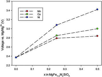 | ||
| Fig. 5 Trends in cell voltage (vs. Mg/Mg2+) as a function of increasing dopant (M = Co, Ni, Mn) on the Fe site in MgFeSiO4. | ||
4. Conclusions
Our fundamental study of olivine-structured MgFeSiO4 as a potential cathode material for Mg batteries shows good reproduction of the experimentally observed structure and reveals key atomic-scale insights into its electrochemical properties. First, we derive an Mg-ion migration energy of 0.6 eV along the 1D channel through a curved pathway (similar to LiFePO4), and a diffusion coefficient (DMg) of 10−9 cm2 s−1 at 300 K from large-scale MD. These ion transport results suggest favourable Mg2+ intercalation kinetics.Secondly, doping of trivalent Al, Ga or V ions on Si sites is unfavourable and suggests low dopant solubility.
Finally, the DFT derived cell voltage for MgFeSiO4 of 2.35 V vs. Mg/Mg2+ agrees well with the available electrochemical data. Mn or Co doping of this structure on the Fe site is predicted to increase the cell voltage to greater than 2.70 V. However, in the case of Ni doping this brings the voltage outside of the useable electrochemical stability range of current electrolytes. Overall, the fundamental insights presented here will inform the future optimisation of silicate electrodes for magnesium batteries.
Acknowledgements
We gratefully acknowledge support from the EPSRC for the Energy Materials Programme grant (EP/K016288) and Archer HPC facilities through the Materials Chemistry Consortium (EP/L000202). J. H acknowledges PhD funding from the University of Bath URS Studentship. We also thank Dr Pieremanuele Canepa (Bath) for useful discussions.References
- D. Aurbach, Z. Lu, A. Schechter, Y. Gofer, H. Gizbar, R. Turgeman, Y. Cohen, M. Moshkovich and E. Levi, Nature, 2000, 407, 724–727 CrossRef CAS PubMed.
- H. D. Yoo, I. Shterenberg, Y. Gofer, G. Gershinsky, N. Pour and D. Aurbach, Energy Environ. Sci., 2013, 6, 2265–2279 CAS.
- E. Levi, Y. Gofer and D. Aurbach, Chem. Mater., 2010, 22, 860–868 CrossRef CAS.
- R. Van Noorden, Nature, 2014, 507(7490), 26–28 CrossRef CAS PubMed.
- P. Canepa, G. Sai Gautam, D. C. Hannah, R. Malik, M. Liu, K. G. Gallagher, K. A. Persson and G. Ceder, Chem. Rev., 2017, 117, 4287–4341 CrossRef CAS PubMed.
- J. Muldoon, C. B. Bucur and T. Gregory, Chem. Rev., 2014, 114, 11683–11720 CrossRef CAS PubMed.
- N. Amir, Y. Vestfrid, O. Chusid, Y. Gofer and D. Aurbach, J. Power Sources, 2007, 174, 1234–1240 CrossRef CAS.
- P. Novak and J. Desilvestro, J. Electrochem. Soc., 1993, 140, 140–144 CrossRef CAS.
- P. Novak, W. Scheifele, F. Joho and O. Haas, J. Electrochem. Soc., 1995, 142, 2544–2550 CrossRef CAS.
- E. Levi, E. Lancry, A. Mitelman, D. Aurbach, O. Isnard and D. Djurado, Chem. Mater., 2006, 18, 3705–3714 CrossRef CAS.
- E. Levi, E. Lancry, A. Mitelman, D. Aurbach, G. Ceder, D. Morgan and O. Isnard, Chem. Mater., 2006, 18, 5492–5503 CrossRef CAS.
- E. Levi, A. Mitelman, O. Isnard, M. Brunelli and D. Aurbach, Inorg. Chem., 2008, 47, 1975–1983 CrossRef CAS PubMed.
- D. B. Le, S. Passerini, F. Coustier, J. Guo, T. Soderstrom, B. B. Owens and W. H. Smyrl, Chem. Mater., 1998, 10, 682–684 CrossRef CAS.
- S. H. Lee, R. A. DiLeo, A. C. Marschilok, K. J. Takeuchi and E. S. Takeuchi, ECS Electrochem. Lett., 2014, 3, 87–90 CrossRef.
- N. Y. Sa, H. Wang, D. L. Proffit, A. L. Lipson, B. Key, M. Liu, Z. X. Feng, T. T. Fister, Y. Ren, C. J. Sun, J. T. Vaughey, P. A. Fenter, K. A. Persson and A. K. Burrell, J. Power Sources, 2016, 323, 44–50 CrossRef CAS.
- Y. W. Cheng, Y. Y. Shao, V. Raju, X. L. Ji, B. L. Mehdi, K. S. Han, M. H. Engelhard, G. S. Li, N. D. Browning, K. T. Mueller and J. Liu, Adv. Funct. Mater., 2016, 26, 3446–3453 CrossRef CAS.
- S. Tepavcevic, Y. Z. Liu, D. H. Zhou, B. Lai, J. Maser, X. B. Zuo, H. Chan, P. Kral, C. S. Johnson, V. Stamenkovic, N. M. Markovic and T. Rajh, ACS Nano, 2015, 9, 8194–8205 CrossRef CAS PubMed.
- R. G. Zhang, X. Q. Yu, K. W. Nam, C. Ling, T. S. Arthur, W. Song, A. M. Knapp, S. N. Ehrlich, X. Q. Yang and M. Matsui, Electrochem. Commun., 2012, 23, 110–113 CrossRef CAS.
- N. Kumagai, S. Komaba and H. Sakai, J. Power Sources, 2001, 97, 515–517 CrossRef.
- X. Q. Sun, V. Duffort, B. L. Mehdi, N. D. Browning and L. F. Nazar, Chem. Mater., 2016, 28, 534–542 CrossRef CAS.
- C. Ling, R. G. Zhang, T. S. Arthur and F. Mizuno, Chem. Mater., 2015, 27, 5799–5807 CrossRef CAS.
- K. W. Nam, S. Kim, S. Lee, M. Salama, I. Shterenberg, Y. Gofer, J. S. Kim, E. Yang, C. S. Park, S. S. Lee, W. S. Chang, S. G. Doo, Y. N. Jo, Y. Jung, D. Aurbach and J. W. Choi, Nano Lett., 2015, 15, 4071–4079 CrossRef CAS PubMed.
- L. Wang, K. Asheim, P. E. Vullum, A. M. Svensson and F. Vullum-Bruer, Chem. Mater., 2016, 28, 6459–6470 CrossRef CAS.
- R. Zhang, T. S. Arthur, C. Ling and F. Mizuno, J. Power Sources, 2015, 282, 630–638 CrossRef CAS.
- L. W. F. Wan, B. R. Perdue, C. A. Apblett and D. Prendergast, Chem. Mater., 2015, 27, 5932–5940 CrossRef CAS.
- X. Q. Sun, P. Bonnick, V. Duffort, M. Liu, Z. Q. Rong, K. A. Persson, G. Ceder and L. F. Nazar, Energy Environ. Sci., 2016, 9, 2273–2277 CAS.
- J. C. Knight, S. Therese and A. Manthiram, ACS Appl. Mater. Interfaces, 2015, 7, 22953–22961 CAS.
- C. Kim, P. J. Phillips, B. Key, T. H. Yi, D. Nordlund, Y. S. Yu, R. D. Bayliss, S. D. Han, M. N. He, Z. C. Zhang, A. K. Burrell, R. F. Klie and J. Cabana, Adv. Mater., 2015, 27, 3377–3384 CrossRef CAS PubMed.
- M. Liu, Z. Q. Rong, R. Malik, P. Canepa, A. Jain, G. Ceder and K. A. Persson, Energy Environ. Sci., 2015, 8, 964–974 CAS.
- Z. Feng, J. Yang, Y. NuLi, J. Wang, X. Wang and Z. Wang, Electrochem. Commun., 2008, 10, 1291–1294 CrossRef CAS.
- Y. NuLi, Y. Zheng, Y. Wang, J. Yang and J. Wang, J. Mater. Chem., 2011, 21, 12437–12443 RSC.
- Y. NuLi, Y. Zheng, F. Wang, J. Yang, A. I. Minett, J. Wang and J. Chen, Electrochem. Commun., 2011, 13, 1143–1146 CrossRef CAS.
- C. Ling, D. Banerjee, W. Song, M. Zhang and M. Matsui, J. Mater. Chem., 2012, 22, 13517–13523 RSC.
- Y. Orikasa, T. Masese, Y. Koyama, T. Mori, M. Hattori, K. Yamamoto, T. Okado, Z. D. Huang, T. Minato, C. Tassel, J. Kim, Y. Kobayashi, T. Abe, H. Kageyama and Y. Uchimoto, Sci. Rep., 2014, 4, 5622 CrossRef CAS PubMed.
- Y. Zheng, Y. NuLi, Q. Chen, Y. Wang, J. Yang and J. Wang, Electrochim. Acta, 2012, 66, 75–81 CrossRef CAS.
- T. Mori, T. Masese, Y. Orikasa, Z. D. Huang, T. Okado, J. Kim and Y. Uchimoto, Phys. Chem. Chem. Phys., 2016, 18, 13524–13529 RSC.
- M. S. Islam, R. Dominko, C. Masquelier, C. Sirisopanaporn, A. R. Armstrong and P. G. Bruce, J. Mater. Chem., 2011, 21, 9811–9818 RSC.
- S. A. T. Redfern, G. Artioli, R. Rinaldi, C. M. B. Henderson, K. S. Knight and B. J. Wood, Phys. Chem. Miner., 2000, 27, 630–637 CrossRef CAS.
- S. Chatterjee, S. Sengupta, T. Saha-Dasgupta, K. Chatterjee and N. Mandal, Phys. Rev. B: Condens. Matter Mater. Phys., 2009, 79, 115103 CrossRef.
- S. Chatterjee, S. Bhattacharyya, S. Sengupta and T. Saha-Dasgupta, Phys. Chem. Miner., 2011, 38, 259–265 CrossRef CAS.
- R. G. Zhang and C. Ling, ACS Appl. Mater. Interfaces, 2016, 8, 18018–18026 CAS.
- M. S. Islam and C. A. J. Fisher, Chem. Soc. Rev., 2013, 43, 185–204 RSC.
- C. R. A. Catlow, Computer Modelling in Inorganic Crystallography, Academic Press, 1997 Search PubMed.
- M. S. Islam, D. J. Driscoll, C. A. J. Fisher and P. R. Slater, Chem. Mater., 2005, 17, 5085–5092 CrossRef CAS.
- C. Tealdi, J. Heath and M. S. Islam, J. Mater. Chem. A, 2016, 4, 6998–7004 CAS.
- R. Tripathi, S. M. Wood, M. S. Islam and L. F. Nazar, Energy Environ. Sci., 2013, 6, 2257–2264 CAS.
- N. Kuganathan and M. S. Islam, Chem. Mater., 2009, 21, 5196–5202 CrossRef CAS.
- C. A. J. Fisher, N. Kuganathan and M. S. Islam, J. Mater. Chem. A, 2013, 1, 4207–4214 CAS.
- A. R. Armstrong, N. Kuganathan, M. S. Islam and P. G. Bruce, J. Am. Chem. Soc., 2011, 133, 13031–13035 CrossRef CAS PubMed.
- J. C. Treacher, S. M. Wood, M. S. Islam and E. Kendrick, Phys. Chem. Chem. Phys., 2016, 18, 32744–32752 RSC.
- B. G. Dick and A. W. Overhauser, Phys. Rev., 1958, 112, 90–103 CrossRef.
- G. V. Lewis and C. R. A. Catlow, J. Phys. C: Solid State Phys., 1985, 18, 1149–1161 CrossRef CAS.
- J. D. Gale and A. L. Rohl, Mol. Simul., 2003, 29, 291–341 CrossRef CAS.
- S. Plimpton, J. Comput. Phys., 1995, 117, 1–19 CrossRef CAS.
- A. Pedone, G. Malavasi, M. C. Menziani, A. N. Cormack and U. Segre, J. Phys. Chem. B, 2006, 110, 11780–11795 CrossRef CAS PubMed.
- S. M. Wood, C. Eames, E. Kendrick and M. S. Islam, J. Phys. Chem. C, 2015, 119, 15935–15941 CAS.
- A. R. Armstrong, C. Lyness, P. M. Panchmatia, M. S. Islam and P. G. Bruce, Nat. Mater., 2011, 10, 223–229 CrossRef CAS PubMed.
- C. Eames, A. R. Armstrong, P. G. Bruce and M. S. Islam, Chem. Mater., 2012, 24, 2155–2161 CrossRef CAS.
- Y. Yuan, C. Zhan, K. He, H. Chen, W. Yao, S. Sharifi-Asl, B. Song, Z. Yang, A. Nie, X. Luo, H. Wang, S. M. Wood, K. Amine, M. S. Islam, J. Lu and R. Shahbazian-Yassar, Nat. Commun., 2016, 7, 13374 CrossRef CAS PubMed.
- G. Kresse and J. Furthmuller, Phys. Rev. B: Condens. Matter Mater. Phys., 1996, 54, 11169–11186 CrossRef CAS.
- G. Kresse and D. Joubert, Phys. Rev. B: Condens. Matter Mater. Phys., 1999, 59, 1758–1775 CrossRef CAS.
- P. E. Blochl, Phys. Rev. B: Condens. Matter Mater. Phys., 1994, 50, 17953–17979 CrossRef.
- J. P. Perdew, K. Burke and M. Ernzerhof, Phys. Rev. Lett., 1996, 77, 3865–3868 CrossRef CAS PubMed.
- M. E. Arroyo-de Dompablo, M. Armand, J. M. Tarascon and U. Amador, Electrochem. Commun., 2006, 8, 1292–1298 CrossRef CAS.
- S.-I. Nishimura, G. Kobayashi, K. Ohoyama, R. Kanno, M. Yashima and A. Yamada, Nat. Mater., 2008, 7, 707–711 CrossRef CAS PubMed.
- Z. Q. Rong, R. Malik, P. Canepa, G. S. Gautam, M. Liu, A. Jain, K. Persson and G. Ceder, Chem. Mater., 2015, 27, 6016–6021 CrossRef CAS.
- C. Tealdi, C. Spreafico and P. Mustarelli, J. Mater. Chem., 2012, 22, 24870–24876 RSC.
- J. D. Wu, G. H. Gao, G. M. Wu, B. Liu, H. Y. Yang, X. W. Zhou and J. C. Wang, Phys. Chem. Chem. Phys., 2014, 16, 22974–22978 RSC.
- M. M. Huie, D. C. Bock, E. S. Takeuchi, A. C. Marschilok and K. J. Takeuchi, Coord. Chem. Rev., 2015, 287, 15–27 CrossRef CAS.
- P. Saha, M. K. Datta, O. I. Velikokhatnyi, A. Manivannan, D. Alman and P. N. Kumta, Prog. Mater. Sci., 2014, 66, 1–86 CrossRef CAS.
- G. Gershinsky, H. D. Yoo, Y. Gofer and D. Aurbach, Langmuir, 2013, 29, 10964–10972 CrossRef CAS PubMed.
- Z. Z. Feng, J. Yang, Y. N. NuLi and J. L. Wang, J. Power Sources, 2008, 184, 604–609 CrossRef CAS.
- A. Yamada, M. Hosoya, S. C. Chung, Y. Kudo, K. Hinokuma, K. Y. Liu and Y. Nishi, J. Power Sources, 2003, 119, 232–238 CrossRef.
- C. Masquelier and L. Croguennec, Chem. Rev., 2013, 113, 6552–6591 CrossRef CAS PubMed.
Footnote |
| † Electronic supplementary information (ESI) available. See DOI: 10.1039/c7ta03201c |
| This journal is © The Royal Society of Chemistry 2017 |

