 Open Access Article
Creative Commons Attribution 3.0 Unported Licence
One-step radiation synthesis of gel polymer electrolytes with high ionic conductivity for lithium-ion batteries†
Yimeng
Wang
 a,
Jingyi
Qiu
b,
Jing
Peng
a,
Jiuqiang
Li
a and
Maolin
Zhai
a,
Jingyi
Qiu
b,
Jing
Peng
a,
Jiuqiang
Li
a and
Maolin
Zhai
 *a
*a
aBeijing National Laboratory for Molecular Sciences, Radiochemistry and Radiation Chemistry Key Laboratory of Fundamental Science, The Key Laboratory of Polymer Chemistry and Physics of the Ministry of Education, College of Chemistry and Molecular Engineering, Peking University, Beijing 100871, China. E-mail: mlzhai@pku.edu.cn
bInstitute of Chemical Defense, Beijing 100191, China
First published on 16th May 2017
Abstract
We demonstrated a one-step synthesis method for a novel gel polymer electrolyte (named PDMP-Li GPE) based on 3-(dimethylamino) propyl methacrylate, poly(ethylene glycol) diacrylate and 1 M LiPF6 liquid electrolyte solution by a γ-radiation technique for lithium-ion batteries. The resultant PDMP-Li GPE exhibited good thermal stability, excellent mechanical strength and high ionic conductivity, and the highest ionic conductivity reached 8.88 × 10⁻³ S cm−1 at 25 °C. The LiFePO4/PDMP-Li GPE/graphite pouch-type cell exhibited more than 97% columbic efficiency and the capacity retention was about 86% after 50 cycles at 0.1C. With these outstanding characteristics, it is expected to be a promising candidate for the application in polymer lithium-ion batteries.
Introduction
Lithium-ion batteries have gained an unprecedented importance in the last several decades as an energy storage component of portable devices such as cell phones, laptop computers and so on.1–4 However, some serious problems including leakage, flames and explosions have been reported to happen in the application of lithium-ion batteries with liquid electrolytes, because of the existence of highly flammable organic liquid electrolytes.5 The use of solvent-free solid electrolytes is the ideal way to solve the current safety problem of liquid electrolytes, but this advantage comes with a considerably reduced conductivity.6 To combine the positive properties of liquid and solid polymer electrolytes, gel polymer electrolytes (GPEs) have been introduced, which have higher ionic conductivity and more stability than solid polymer electrolytes and liquid electrolytes, respectively, and consequently they could provide an alternative solution to the safety problem of lithium-ion batteries.7,8 Furthermore, compared with the commercial liquid electrolytes, the main advantages of GPEs in lithium-ion batteries are their non-leakage nature and higher thermal stability, and they can be used to prepare flexible, thinner and smaller electrochemical devices.Recently, various polymers such as poly(acrylonitrile) (PAN),9,10 poly(vinylidene fluoride) (PVDF)11,12 and poly(methyl methacrylate) (PMMA)13–15 have been widely used as polymer matrices for the preparation of GPEs in the lithium-ion batteries. The ionic conductivity of these systems was around 10−5 to 10−3 S cm−1 at room temperature, which was influenced by the amount of the liquid electrolyte uptake within polymer matrices.16 However, the increase of liquid electrolyte uptake results in the low mechanical properties of GPEs, that is, the conductivity and mechanical stability of GPEs are mutually exclusive. Notably, PMMA has received considerable attention due to its similar structure to carbonate-based solvents applied in the conventional liquid electrolytes, which suggests that it may have good compatibility with the lithium salts and offer a good interfacial contact with commonly used electrodes. Meanwhile, its amorphous structure is beneficial to the ionic conductivity (1 × 10⁻³ S cm−1 at ambient temperature), but still cannot meet the needs of practical applications.
Besides, the GPEs can be prepared by the ultraviolet (UV)-curing,17,18 solvent-casting technique,19,20 thermal method16,21 and electrospinning technique.22–25 Compared with traditional methods, γ-radiation is a simpler, cleaner and more effective technique which is suitable for large-scale industrial production. It can be carried out at room temperature without initiators and catalysts. In the case of the in situ polymerization technique, the preparation of the gel electrolyte and the assembly of the batteries could be achieved in one step, thereby improving the production efficiency and reducing the costs.
Depending on the method of packaging, batteries can have a coin, cylindrical, prismatic, or pouch shape. According to Li's work,26 the large format pouch-type cells are widely used for high power applications. Compared with the coin-type half cells whose anode electrode is lithium metal, the pouch-type full cells are cheaper, safer, more practical and relevant to Li-ion battery devices.27 Besides, the Al-plastic pouch has advantages of light weight, hermetic shielding, and flexibility for use in various device designs.28
In this work, a novel GPE based on 3-(dimethylamino) propyl methacrylate (DMAPMA), poly(ethylene glycol) diacrylate (PEGDMA) and 1 M LiPF6 liquid electrolyte solution was prepared by the γ-radiation technique through a one-step synthesis method, called the PDMP-Li GPE. The thermal stability and the mechanical properties of the resultant gels have been tested. And the ionic conductivity of the gel samples was studied by impedance spectroscopy. Finally, in order to confirm the possibility of the PDMP-Li GPE usage in lithium-ion batteries, we tested its electrochemical properties in the pouch-type full cells.
Experimental
Materials
2-Dimethylaminomethacrylate (98%), methacryloyl chloride (98%), lithium hexafluorophosphate (LiPF6, 98%) and poly(ethylene glycol) diacrylate (PEGDMA, average Mn = 400) were purchased from J&K and used without further purification. The liquid electrolyte (1 M LiPF6 in EC/DEC 1![[thin space (1/6-em)]](https://www.rsc.org/images/entities/char_2009.gif) :
:![[thin space (1/6-em)]](https://www.rsc.org/images/entities/char_2009.gif) 1 v/v) without any other additives (such as safety agents or fire retardant additives) was purchased from Tinci Company and used as supplied. Other chemicals were analytical-grade reagents obtained from Beijing Chemical Company and used as received.
1 v/v) without any other additives (such as safety agents or fire retardant additives) was purchased from Tinci Company and used as supplied. Other chemicals were analytical-grade reagents obtained from Beijing Chemical Company and used as received.
Synthesis of 3-(dimethylamino) propyl methacrylate (DMAPMA)
3-(Dimethylamino) propyl methacrylate (DMAPMA) was prepared and purified according to the procedure published earlier by P. van de Wetering (Scheme 1).29 Briefly, to an ice-cooled solution of DMAP-OH (3.60 mL, 30 mmol) in CH2Cl2 (300 mL) triethylamine (8.32 mL, 60 mmol) was added under magnetic stirring, followed by the addition of methacryloyl chloride (5.38 mL, 54 mmol) dropwise after 30 minutes. After being stirred for 5 h at ambient temperature, the orange liquid was washed with saturated NaHCO3 solution, and then the organic layer was dried on Na2SO4 and filtered. The product was isolated by evaporation under reduced pressure, giving a 80% yield. 1H NMR (400 MHz, CDCl3, TMS standard, r.t.): δ (ppm) 6.10 (s, 1H, C![[double bond, length as m-dash]](https://www.rsc.org/images/entities/char_e001.gif) CH), 5.55 (s, 1H, C
CH), 5.55 (s, 1H, C![[double bond, length as m-dash]](https://www.rsc.org/images/entities/char_e001.gif) CH), 4.20 (t, 2H, OCH2), 2.37 (t, 2H, NCH2), 2.24 (s, 6H, N(CH3)2), 1.95 (s, 3H, C
CH), 4.20 (t, 2H, OCH2), 2.37 (t, 2H, NCH2), 2.24 (s, 6H, N(CH3)2), 1.95 (s, 3H, C![[double bond, length as m-dash]](https://www.rsc.org/images/entities/char_e001.gif) CCH3), and 1.85 (m, 2H, OCH2CH2CH2N).
CCH3), and 1.85 (m, 2H, OCH2CH2CH2N).
Synthesis of the PDMP-Li GPE
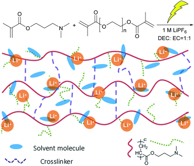
The synthesis route of the PDMP-Li GPE is shown in Scheme 2. The concentrations of DMAPMA (monomer) and PEGDMA (cross-linker) were 0.75 mol L−1 and 0.05 mol L−1, respectively. DMAPMA/PEGDMA was placed in a glass tube of 10 mm diameter and dissolved in the liquid electrolyte. The mixture was bubbled with nitrogen for 15 min. Finally, the tube was sealed and irradiated to form the gel with 10 kGy dose at a dose rate of 80 Gy min−1 at room temperature. The resulting gels were cut into cylindrical pieces and dried in air at 25 °C for one day. For comparison, PDMAPMA gels (short for PDMP) were prepared under the same gelation conditions but without the addition of LiPF6.Characterization of the PDMP-Li GPE
Micro-FTIR and thermogravimetric analysis (TGA) were used to characterize the composition and thermal stability of the resultant gels. Micro-FTIR analysis was performed using a Nicolet (Magna-IR 750) spectrometer in the range of 5000–600 cm−1. TGA was carried out using a TA Q600 thermal analyzer under a nitrogen atmosphere, over a temperature range of 25–600 °C with a heating rate of 5 °C min. The gel fraction (GF) is defined as:| Gel fraction (%) = Wg/Wo × 100 | (1) |
The mechanical properties were measured using the as-synthesized gel which was cut into cylindrical pieces (d = 10 mm), and then the compression strength test was performed by using an Instron 3365 material test system at room temperature.
The electrochemical measurements were recorded using an electrochemical instrument (CHI-660D, Shanghai). The ionic conductivity of the GPE was measured with a symmetrical cell SS/GPE/SS by EIS. The GPE was sandwiched between two SS discs (diameter Ø = 16 mm). The ionic conductivity of the GPE was calculated from the bulk electrolyte resistance (R) according to:
 | (2) |
In situ synthesis and characterization of the PDMP-Li GPE in pouch-type Li-ion cells
In situ synthesis and characterization of the PDMP-Li GPE were carried out in LiFePO4/graphite pouch-type cells. The production process of the pouch-type cells was similar to the commercial ones. The positive electrodes were obtained by coating the mixed slurry containing 92 wt% commercial-grade LiFePO4 active material, 3 wt% Super P, 1 wt% conductive graphite KS6 and 4 wt% poly(vinylidene fluoride) (PVDF) onto an aluminium foil collector. The negative electrodes were prepared by coating the mixed slurry of 93 wt% commercial-grade man-made graphite, 3 wt% Super P and 4 wt% poly(vinylidene fluoride) (PVDF) onto a copper foil. The chosen separator was commercial grade. The negative electrode, positive electrode, and separators (Celgard 2325, USA, 25 μm in thickness) were subsequently rolled together to make a cell core. The cell core was placed into cell shells made from aluminium films and dried at 85 °C overnight. The structure of pouch-type Li-ion cells and the preparation process of the PDMP-Li GPE are shown in Scheme S1.† Injection of the excessive mixture liquid electrolyte (1 M LiPF6 in EC/DEC 1![[thin space (1/6-em)]](https://www.rsc.org/images/entities/char_2009.gif) :
:![[thin space (1/6-em)]](https://www.rsc.org/images/entities/char_2009.gif) 1 v/v) containing DMAPMA/PEGDMA (0.75 mol L−1 and 0.05 mol L−1, respectively) was carried out in an Ar-filled glovebox, after resting for 30 min, and then the excess electrolyte and the formed gas were removed with a vacuum degassing machine to facilitate diffusion of the electrolyte into the cell core, the final remainder being the electrolyte of about 5 g A−1 h−1. Subsequently, the cells were sealed with a sealing machine and the assembled cells were placed in an oven (40 °C) for 24 h, ensuring that the electrolyte was fully absorbed.
1 v/v) containing DMAPMA/PEGDMA (0.75 mol L−1 and 0.05 mol L−1, respectively) was carried out in an Ar-filled glovebox, after resting for 30 min, and then the excess electrolyte and the formed gas were removed with a vacuum degassing machine to facilitate diffusion of the electrolyte into the cell core, the final remainder being the electrolyte of about 5 g A−1 h−1. Subsequently, the cells were sealed with a sealing machine and the assembled cells were placed in an oven (40 °C) for 24 h, ensuring that the electrolyte was fully absorbed.
Then the cells were irradiated with 10 kGy dose at a dose rate of 80 Gy min−1 at room temperature. In this process, the radiation-induced polymerization and crosslinking of DMAPMA and PEGDMA in the liquid electrolyte took place. Since the absorbed dose was only 10 kGy, during the irradiation, there was no significant change in the separators, which are mainly composed of polypropylene and polyethylene.30,31 Meanwhile, the PDMP-Li GPE was prepared in situ inside the cells by the one-step method.
The cell performances including charge–discharge curve and cyclic property were examined by using the charge–discharge testing device (NEWARE CT-3008-5V500 mA, Shenzhen, China). The cycling performance of the cells was evaluated at 0.1C and 25 °C between 2.3 V and 3.6 V. All the cells were charged at room temperature by the constant-current/constant-voltage (CC–CV) protocol. That is, the cells were charged at a certain current rate until the voltage reached to a limited voltage, followed by holding the voltage until the current dropped to 10 mA.
Electrochemical impedance spectroscopy (EIS) was performed using a frequency response analyser (CHI-660D, Shanghai) with an electrochemical interface in the frequency range from 100 kHz to 0.1 Hz at an amplitude of 5 mV and 25 °C.
The morphology of the electrode was observed using a scanning electron microscope (SEM, Hitachi S-4800, Japan), and the electrodes here were dried under vacuum at 60 °C for three days.
Results and discussion
Preparation and characterization of PDMP-Li GPE
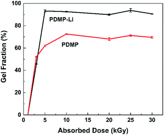
It is widely known that radiation-induced polymerization and crosslinking is an efficient and clean method, which needs no initiators and can be done at room temperature. In this process, the polymerization and crosslinking of the monomer is initiated by the radicals generated from the radiation. As shown in Scheme 2, a certain percentage of DMAPMA and PEGDMA were dissolved in the liquid electrolyte, and after the system was irradiated, the DMAPMA monomer and the PEGDMA crosslinker formed an orange gel with the liquid electrolyte involved. The crosslinking network ensured that the organic solvents won't leak, which improved the safety of the lithium-ion batteries with the gel electrolyte.Gel fractions (GF) of PDMP-Li GPE and PDMP gels as a function of absorbed dose are shown in Fig. 1. Similar to other gels, the formation of gels starts at a critical absorbed dose (gelation dose), and the gel fraction increases sharply with the increasing absorbed dose in a narrow range and then levels off.32 It was found that the PDMP-Li GPEs were synthesized at a lower absorbed dose and the gel fractions were much higher than those of PDMP gel without LiPF6. It is worth noting that high GF could be gained with a relatively low absorbed dose, which brings in the advantage of avoiding radiation side effects. And the radiation-induced polymerization and crosslinking was much more efficient for the PDMP-Li GPE system, obtaining GF of ca. 93% at only 5 kGy, maybe the LiPF6 inside the system as an additive improved the formation of the crosslinking network.33
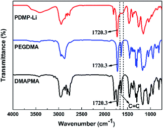
FTIR and TGA were carried out to characterize the chemical structure and thermal stability of the resultant gels, respectively. Herein, the FTIR spectra of the PDMP-Li GPE, PEGDMA crosslinker and DMAPMA monomer are shown in Fig. 2. For the PEGDMA crosslinker and DMAPMA monomer, the peaks of 1637.3 cm−1 and 1720.3 cm−1 are ascribed to the functional groups of C![[double bond, length as m-dash]](https://www.rsc.org/images/entities/char_e001.gif) C and C
C and C![[double bond, length as m-dash]](https://www.rsc.org/images/entities/char_e001.gif) O, respectively. Compared with the FTIR spectra of PEGDMA and DMAPMA, it can be found that the PDMP-Li GPE showed the absorption peak at 1720.3 cm−1 for C
O, respectively. Compared with the FTIR spectra of PEGDMA and DMAPMA, it can be found that the PDMP-Li GPE showed the absorption peak at 1720.3 cm−1 for C![[double bond, length as m-dash]](https://www.rsc.org/images/entities/char_e001.gif) O, while the absorption peak of the C
O, while the absorption peak of the C![[double bond, length as m-dash]](https://www.rsc.org/images/entities/char_e001.gif) C group disappeared. The FTIR results suggest that the crosslinking network is obtained through opening the C
C group disappeared. The FTIR results suggest that the crosslinking network is obtained through opening the C![[double bond, length as m-dash]](https://www.rsc.org/images/entities/char_e001.gif) C double bonds in the monomer and crosslinker, while the main functional groups remained.
C double bonds in the monomer and crosslinker, while the main functional groups remained.
Fig. 3 shows the TGA curves of LiPF6, liquid electrolyte (1 M LiPF6 in EC![[thin space (1/6-em)]](https://www.rsc.org/images/entities/char_2009.gif) :
:![[thin space (1/6-em)]](https://www.rsc.org/images/entities/char_2009.gif) DEC 1
DEC 1![[thin space (1/6-em)]](https://www.rsc.org/images/entities/char_2009.gif) :
:![[thin space (1/6-em)]](https://www.rsc.org/images/entities/char_2009.gif) 1 v/v), PDMAPMA gel and PDMP-Li GPE. By comparing the weight loss as a function of temperature, the order of thermal stability is liquid electrolyte < LiPF6 < PDMP-Li GPE < PDMAPMA gel. It is well known that the commercial LiPF6 is very unstable at elevated temperature as shown in curve 3. LiPF6 decomposes in two steps, the first decomposition step is attributed to the traces of water and its decomposition occurs according to reaction (3).34
1 v/v), PDMAPMA gel and PDMP-Li GPE. By comparing the weight loss as a function of temperature, the order of thermal stability is liquid electrolyte < LiPF6 < PDMP-Li GPE < PDMAPMA gel. It is well known that the commercial LiPF6 is very unstable at elevated temperature as shown in curve 3. LiPF6 decomposes in two steps, the first decomposition step is attributed to the traces of water and its decomposition occurs according to reaction (3).34
| LiPF6 + H2O → LiF + POF3 + 2HF | (3) |
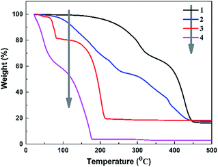 | ||
| Fig. 3 The TGA graph of the samples; curve 1: PDMAPMA gel; curve 2: PDMP-Li GPE; curve 3: LiPF6; and curve 4: liquid electrolyte. | ||
The main decomposition starts at 85 °C, and its decomposition path is a simple dissociation producing lithium fluoride (LiF) as solid and PF5 as gaseous products according to reaction (4).34
| LiPF6 → LiF + PF5 | (4) |
In curve 4, the liquid electrolyte shows the worst thermal stability: the organic solvents start to volatilize at the beginning, and when the temperature reaches 80 °C, the liquid electrolyte retains 80% of its initial weight. Decomposition at temperatures above 80 °C may occur according to reaction (4). As shown in curve 1, pure PDMAPMA gel is thermally stable up to 250 °C; the first decomposition is related to the dimethylamino in the structure of PDMAPMA. Another decomposition is observed at 350 °C to 400 °C, probably due to the carbonization loss of the backbone segments.35 Compared with curve 3 and curve 4, it is obvious that the PDMP-Li GPE expresses more excellent thermal stability (curve 2), i.e., before 100 °C, the PDMP-Li GPE does not lose any weight, indicating the LiPF6 and organic solvents in the gelled network are more stable; for the temperature range of complete thermal decomposition, all the systems are similar. Although the PDMP-Li GPE starts to decompose at 120 °C, which is at the same level as other studies,17,19 and this degradation temperature is still high enough for the practical use.
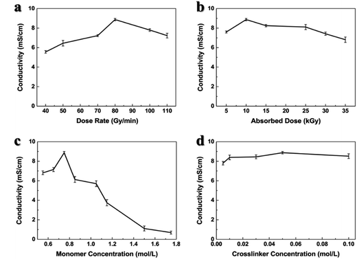
Ionic conductivity of the GPEs plays an important role in the electrochemical performance. In Fig. 4, we studied the factors influencing the ionic conductivity of the PDMP-Li GPE, and determined the optimal synthesis conditions. When the absorbed dose and dose rate are 10 kGy and 80 Gy min−1, the concentration of DMAPMA and PEGDMA are 0.75 mol L−1 and 0.05 mol L−1, respectively; the highest ionic conductivity of the resultant PDMP-Li GPE reaches 8.88 × 10⁻³ S cm−1 at room temperature, which is higher than most results that have been reported in the literature and competitive to the liquid electrolyte that has been widely used in lithium-ion batteries. As the ion transport in the LiPF6 EC/DEC solution is mainly achieved by Li+ ions, the high conductivity in the PDMP-Li GPE is caused by the higher lithium-ion concentration per repeating unit. Huang36 reported that the Li+ ions within the GPEs were mainly solvated by the C![[double bond, length as m-dash]](https://www.rsc.org/images/entities/char_e001.gif) O because of their high electronegativity which dissociated lithium salt and hindered the movement of large PF6− anions. Therefore, because of the strong interaction, the carbonyl oxygen can separate the Li+ and PF6− ions in the PDMP-Li GPE which may prevent the reunion of Li+ and PF6− ions concurrently and create more free Li+ ions. Fig. 4a and b indicated that when the samples were irradiated for a long time, the high ionic conductivity may be decreased, but the order of magnitude of the ionic conductivity was about 10−3 S cm−1 which is still higher than in most reports, as shown in Table 1.
O because of their high electronegativity which dissociated lithium salt and hindered the movement of large PF6− anions. Therefore, because of the strong interaction, the carbonyl oxygen can separate the Li+ and PF6− ions in the PDMP-Li GPE which may prevent the reunion of Li+ and PF6− ions concurrently and create more free Li+ ions. Fig. 4a and b indicated that when the samples were irradiated for a long time, the high ionic conductivity may be decreased, but the order of magnitude of the ionic conductivity was about 10−3 S cm−1 which is still higher than in most reports, as shown in Table 1.
| Gel composition (polymer/electrolyte)a | Ionic conductivity [mS cm−1] | Ref. |
|---|---|---|
| a LiPF6, lithium hexafluorophosphate; LiTFSI, lithium bis(trifluoromethane sulfonimide); EC, ethylene carbonate; EMC, ethyl methyl carbonate; DEC, diethyl carbonate; DMC, dimethyl carbonate; PVDF, poly(vinylidene fluoride); LiPAAOB, lithium polyacrylic acid oxalate borate; OEGMA, oligo(ethylene glycol) methyl ether methacrylate; CCMA, cyclic carbonate methacrylate; BC, boron-containing crosslinker; P(AN-VAc), poly(acrylonitrile-co-vinyl acetate); CA, cellulose acetate; PLLA, poly-L-lactic acid; HNT, halloysite nanotube; PPC, poly(propylene carbonate); P(MMA-AN-VAc), poly(methyl methacrylate-co-acrylonitrile-co-vinyl acetate). | ||
| PVDF–LiPAAOB/LiPF6–EC–DMC–EMC | 0.35 (25 °C) | 11 |
| OEGMA–CCMA/LiPF6–EC–DMC | 2.30 (25 °C) | 17 |
| BC–PVDF/LiTFSI–EC–DEC | 4.20 (30 °C) | 18 |
| P(AN-VAc)–PMMA/LiPF6–EC–DMC–DEC | 3.50 (30 °C) | 22 |
| CA–PLLA–HNT/LiPF6–EC–DMC | 1.52 (25 °C) | 25 |
| PVDF–PPC/LiPF6–EC–DMC | 4.05 (30 °C) | 36 |
| P(MMA-AN-VAc)/LiPF6–EC–DMC–DEC | 3.48 (25 °C) | 37 |
| PDMAPMA/LiPF6–EC–DEC | 8.88 (25 °C) | This work |
Fig. 4c shows the ionic conductivity of the PDMP-Li GPE as a function of DMAPMA concentration. The ionic conductivity first increased with increasing concentration of DMAPMA due to the denser gel network and high degree of gelation which kept the liquid electrolyte inside the gel network, and the maximum ionic conductivity was observed at the DMAPMA concentration of 0.75 mol L−1. Then, the ionic conductivity began to decrease with a further increase of the DMAPMA concentration, because the much denser network caused less liquid electrolyte inside the gel, leading to the decrease.38
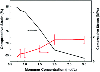
According to Fig. 4, the monomer concentration influences the ionic conductivity most. So in Fig. 5, we observed the stress–strain curves of the resultant PDMP-Li GPE against the monomer concentration at room temperature. Usually, for solid state materials, after being soaked in liquid, the mechanical property becomes worse.39 The compressive stress and the elastic modulus increased with DMAPMA concentration, while compressive strain decreased. The order of magnitude of compressive stress was about 1 MPa, among the monomer concentration from 0.6 mol L−1 to 3.0 mol L−1. The reasonable explanation for this phenomenon is that the higher the monomer concentration, the denser the gel network, which means less liquid electrolyte was absorbed in the network. This makes the gel tougher and hard to compressed. As we can see, when the ionic conductivity reaches 8.88 × 10⁻³ S cm−1, the compressive stress is about 0.4 MPa which is high enough to meet the needs of flexible batteries.
In situ synthesis and properties of the PDMP-Li GPE in pouch-type Li-ion cells
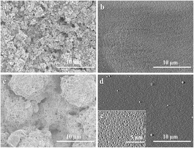
From the above discussion, it can be notified that the PDMP-Li GPE exhibited good thermal stability, excellent mechanical strength and especially presented high ionic conductivity around 8.88 × 10⁻³ S cm−1. To examine the actual application effort of the PDMP-Li GPE on the lithium-ion batteries, the LiFePO4 electrode was chosen as the cathode and the LiFePO4/PDMP-Li GPE/graphite pouch-type cells were assembled. For comparison, the liquid-state LiFePO4/graphite cells were also assembled by using the Celgard 2325 porous membrane as the separator.In order to prove that the PDMP-Li GPE was truly generated inside the pouch-type full cells, we removed the cell's shell and observed that there was some orange gel on the aluminium film. The thickness of the PDMP-Li GPE was ca. 25 μm. We compared the SEM of the electrodes before and after radiation in Fig. 6. It can be seen from Fig. 6a and c that the surface of untreated electrodes was rough and the morphology of the electrodes could be seen clearly. However, the surface of the irradiated electrodes in Fig. 6b and d became extremely flat and seemed like the surface was covered evenly by the gelled layer which confirmed that the PDMP-Li GPE truly existed.
It was found that there were some white spots on the surface of the electrode in Fig. 6d. We speculate that LiPF6 may be precipitated on the surface of GPE. In order to confirm our thought, the obtained cathode in Fig. 6d was further washed with DEC several times and dried under vacuum. As shown in Fig. 6e, it can be seen that there were some small holes on the surface uniformly which confirmed that the holes were produced in situ after the dissolution of LiPF6. Therefore, the liquid electrolyte with DMAPMA and PEGDMA additives was totally gelled uniformly to form the PDMP-Li GPE after radiation in the pouch-type full cells and the high ionic conductivity may be attributed to the evenly distributed LiPF6 within the GPE.
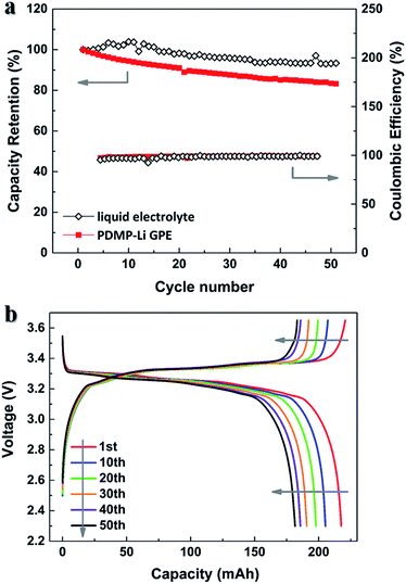
Fig. 7a presents the cycling performances of the LiFePO4/graphite pouch-type cells. The cells were cycled with a constant current of 0.1C rate between 3.6 and 2.3 V. After 50 cycles, the capacity retention of the pouch-type cell with the PDMP-Li GPE achieved a value of 86%, slightly lower than that of the pouch-type cell with the liquid electrolyte, which retained 93% of its initial discharge capacity. These results are in line with the EIS spectra as shown in Fig. S1.† The decrease in discharge capacities of the pouch-type cell with the PDMP-Li GPE may occur due to the formation of passive layers over the electrode surface during cycling. Taking the pouch-type cell with the PDMP-Li GPE for example, the detailed charge and discharge curves are shown in Fig. 7b. The characteristic voltage plateau of LiFePO4 at about 3.3 V was quiet stable. Therefore, the application of the PDMP-Li GPE in pouch-type full cells will not sacrifice the cycling stability of the LiFePO4 cathode, resulted from its high ionic conductivity.
Conclusions
A PDMP-Li GPE consisted of 1 M LiPF6 EC/DEC (1![[thin space (1/6-em)]](https://www.rsc.org/images/entities/char_2009.gif) :
:![[thin space (1/6-em)]](https://www.rsc.org/images/entities/char_2009.gif) 1 in volume) and PDMAPMA gel was synthesized successfully by a one-step method with γ-radiation induced polymerization and crosslinking. The resultant PDMP-Li GPE exhibited high ionic conductivity around 8.88 × 10⁻³ S cm−1, good thermal stability, excellent mechanical integrity and strength to allow the safe operation in lithium-ion batteries. After 50 cycles, the assembled LiFePO4/PDMP-Li GPE/graphite pouch-type cell showed a very stable discharge behavior and little capacity loss under current constant voltage conditions, at a rate of 0.1C and 25 °C. Considering these results, the cell with the PDMP-Li GPE appears to be a promising candidate for lithium-ion batteries.
1 in volume) and PDMAPMA gel was synthesized successfully by a one-step method with γ-radiation induced polymerization and crosslinking. The resultant PDMP-Li GPE exhibited high ionic conductivity around 8.88 × 10⁻³ S cm−1, good thermal stability, excellent mechanical integrity and strength to allow the safe operation in lithium-ion batteries. After 50 cycles, the assembled LiFePO4/PDMP-Li GPE/graphite pouch-type cell showed a very stable discharge behavior and little capacity loss under current constant voltage conditions, at a rate of 0.1C and 25 °C. Considering these results, the cell with the PDMP-Li GPE appears to be a promising candidate for lithium-ion batteries.
Acknowledgements
We thank Wei Wei and Yue Wang from the Institute of Chemical Defense for providing pouch-type cells for testing. The National Natural Science Foundation of China (Project No. 11375019) is acknowledged for supporting this research.Notes and references
- J.-M. Tarascon and M. Armand, Nature, 2001, 414, 359–367 CrossRef CAS PubMed.
- M. Armand and J.-M. Tarascon, Nature, 2008, 451, 652–657 CrossRef CAS PubMed.
- A. Yella, H.-W. Lee, H. N. Tsao, C. Yi, A. K. Chandiran, M. K. Nazeeruddin, E. W.-G. Diau, C.-Y. Yeh, S. M. Zakeeruddin and M. Grätzel, Science, 2011, 334, 629–634 CrossRef CAS PubMed.
- Y. S. Choi and D. M. Kang, J. Power Sources, 2014, 270, 273–280 CrossRef CAS.
- J. B. Goodenough and Y. Kim, Chem. Mater., 2010, 22, 587–603 CrossRef CAS.
- A. M. Christie, S. J. Lilley, E. Staunton, Y. G. Andreev and P. G. Bruce, Nature, 2005, 433, 50–53 CrossRef CAS PubMed.
- D.-W. Kim, J. Power Sources, 1998, 76, 175–179 CrossRef CAS.
- Q. Lu, J. Fang, J. Yang, R. Miao, J. Wang and Y. Nuli, J. Membr. Sci., 2014, 449, 176–183 CrossRef CAS.
- P.-L. Kuo, C.-A. Wu, C.-Y. Lu, C.-H. Tsao, C.-H. Hsu and S.-S. Hou, ACS Appl. Mater. Interfaces, 2014, 6, 3156–3162 CAS.
- P. Raghavan, J. Manuel, X. Zhao, D.-S. Kim, J.-H. Ahn and C. Nah, J. Power Sources, 2011, 196, 6742–6749 CrossRef CAS.
- Y. Zhu, S. Xiao, Y. Shi, Y. Yang and Y. Wu, J. Mater. Chem. A, 2013, 1, 7790–7797 CAS.
- Y. Zhu, S. Xiao, Y. Shi, Y. Yang, Y. Hou and Y. Wu, Adv. Energy Mater., 2014, 4, 1300647–1300656 CrossRef.
- D. Kumar and S. A. Hashmi, J. Power Sources, 2010, 195, 5101–5108 CrossRef CAS.
- H.-R. Jung and W.-J. Lee, Electrochim. Acta, 2011, 58, 674–680 CrossRef CAS.
- T. Chen, Y. Liao, X. Wang, X. Luo, X. Li and W. Li, Electrochim. Acta, 2016, 191, 923–932 CrossRef CAS.
- J. Zheng, X. Li, Y. Yu, X. Zhen, Y. Song, X. Feng and Y. Zhao, J. Solid State Electrochem., 2014, 18, 2013–2018 CrossRef CAS.
- S. D. Tillmann, P. Isken and A. Lex-Balducci, J. Power Sources, 2014, 271, 239–244 CrossRef CAS.
- J. Shim, J. S. Lee, J. H. Lee, H. J. Kim and J. C. Lee, ACS Appl. Mater. Interfaces, 2016, 8, 27740–27752 CAS.
- S. Jankowsky, M. M. Hiller, O. Fromm, M. Winter and H. D. Wiemhöfer, Electrochim. Acta, 2015, 155, 364–371 CrossRef CAS.
- P.-L. Kuo, C.-H. Tsao, C.-H. Hsu, S.-T. Chen and H.-M. Hsu, J. Membr. Sci., 2016, 499, 462–469 CrossRef CAS.
- D. Zhou, Y.-B. He, Q. Cai, X. Qin, B. Li, H. Du, Q.-H. Yang and F. Kang, J. Mater. Chem. A, 2014, 2, 20059–20066 CAS.
- S.-H. Wang, P.-L. Kuo, C.-T. Hsieh and H. Teng, ACS Appl. Mater. Interfaces, 2014, 6, 19360–19370 CAS.
- W. Li, Z. Li, C. Yang, Q. Xiao, G. Lei and Y. Ding, RSC Adv., 2016, 6, 47833–47839 RSC.
- S.-H. Wang, Y.-Y. Lin, C.-Y. Teng, Y.-M. Chen, P.-L. Kuo, Y.-L. Lee, C.-T. Hsieh and H. Teng, ACS Appl. Mater. Interfaces, 2016, 8, 14776–14787 CAS.
- M. Zhu, J. Lan, C. Tan, G. Sui and X. Yang, J. Mater. Chem. A, 2016, 4, 12136–12143 CAS.
- X. Li, S.-Y. Choe and W. T. Joe, J. Power Sources, 2015, 294, 545–555 CrossRef CAS.
- E. C. Self, E. C. McRen, R. Wycisk and P. N. Pintauro, Electrochim. Acta, 2016, 214, 139–146 CrossRef CAS.
- K.-Y. Kang, Y.-G. Lee, D. O. Shin, J.-C. Kim and K. M. Kim, Electrochim. Acta, 2014, 138, 294–301 CrossRef CAS.
- P. van de Wetering, N. J. Zuidam, M. J. van Steenbergen, O. A. G. J. van der Houwen, W. J. M. Underberg and W. E. Hennink, Macromolecules, 1998, 31, 8063–8068 CrossRef CAS.
- H. A. Khonakdar, S. H. Jafari, U. Wagenknecht and D. Jehnichen, Radiat. Phys. Chem., 2006, 75, 78–86 CrossRef CAS.
- A. Ventura, Y. Ngono-Ravache, H. Marie, D. Levavasseur-Marie, R. Legay, V. Dauvois, T. Chenal, M. Visseaux and E. Balanzat, J. Phys. Chem. B, 2016, 120, 10367–10380 CrossRef CAS PubMed.
- C. Li, L. Xu, M. Zhai, J. Peng, C. Yang, J. Li and G. Wei, Polymer, 2009, 50, 4888–4894 CrossRef CAS.
- C. Li, G. Wang, H. Gao, M. Zhai and J. Li, J. Appl. Polym. Sci., 2014, 131 DOI:10.1002/app.39998.
- H. Yang, G. V. Zhuang and P. N. Ross Jr, J. Power Sources, 2006, 161, 573–579 CrossRef CAS.
- D. P. Nava, G. Guzmán, J. Vazquez-Arenas, J. Cardoso, B. Gomez and I. Gonzalez, Solid State Ionics, 2016, 290, 98–107 CrossRef CAS.
- X. Huang, S. Zeng, J. Liu, T. He, L. Sun, D. Xu, X. Yu, Y. Luo, W. Zhou and J. Wu, J. Phys. Chem. C, 2015, 119, 27882–27891 CAS.
- Y. Liao, M. Rao, W. Li, C. Tan, J. Yi and L. Chen, Electrochim. Acta, 2009, 54, 6396–6402 CrossRef CAS.
- W. Kang, N. Deng, X. Ma, J. Ju, L. Li, X. Liu and B. Cheng, Electrochim. Acta, 2016, 216, 276–286 CrossRef CAS.
- T. Hamada, H. Fukasawa, S. Hasegawa, A. Miyashita and Y. Maekawa, Int. J. Hydrogen Energy, 2016, 41, 18621–18630 CrossRef CAS.
Footnote |
| † Electronic supplementary information (ESI) available. See DOI: 10.1039/c7ta02291c |
| This journal is © The Royal Society of Chemistry 2017 |


