 Open Access Article
Creative Commons Attribution 3.0 Unported Licence
Energy efficient synthesis of highly ordered mesoporous carbon nitrides with uniform rods and their superior CO2 adsorption capacity†
Kripal S.
Lakhi
a,
Dae-Hwan
Park
*a,
Gurwinder
Singh
a,
Siddulu N.
Talapaneni
a,
Ugo
Ravon
b,
Khalid
Al-Bahily
b and
Ajayan
Vinu
 *a
*a
aFuture Industries Institute, Division of Information Technology, Engineering and Environment, University of South Australia, Mawson Lakes Campus, Adelaide 5095, Australia. E-mail: Ajayan.Vinu@unisa.edu.au; Daehwan.Park@unisa.edu.au; Fax: +61-8-830-25639; Tel: +61-8-830-25384
bSABIC Corporate Research and Development Center at KAUST, Saudi Basic Industries Corporation, Thuwal 23955, Saudi Arabia
First published on 11th January 2017
Abstract
An energy efficient route for the synthesis of mesoporous carbon nitride (MCN) materials with highly ordered mesopores and a rod shaped morphology from uncalcined mesoporous SBA-15 (SEW-SBA-15) templates with a controlled morphology through a nanocasting technique using ethylenediamine and carbon tetrachloride as carbon and nitrogen sources is introduced. Porosity in the SBA-15 templates is created by washing with ethanol whereas the controlled rod shaped morphology in the nanotemplates is obtained by modifying the synthesis conditions from stirring to static conditions. The prepared MCN from the SEW-SBA-15 templates retains the morphological and structural order of the template. By tuning the pore diameter of SEW-SBA-15, it is possible to prepare MCN with tuneable pore diameters, which exhibits a specific BET surface area of 596–655 m2 g−1, pore diameter of 2.8–5.7 nm, and specific pore volume of 0.49–0.89 cm3 g−1. These values are similar to those of MCN-1 prepared from the calcined SBA-15 template with an irregular morphology. The SEW-MCN-1-T samples are used as CO2 adsorbents at 0, 10 and 25 °C and pressures from 1 up to 30 bar. Among the samples, the SEW-MCN-1-130 sample with the highest specific surface area, uniform particle size and morphology, and the largest pore volume exhibits the highest CO2 uptake capacity of 15.4 mmol g−1 at 0 °C and 30 bar, which is similar to the sample prepared by the calcination route but higher than that of activated carbon and multiwalled carbon nanotubes. This is the first report of the MCN prepared from uncalcined SBA-15 which helps to avoid the required energy intensive calcination step of the template and offers a promising system for CO2 capture.
1. Introduction
Carbon dioxide (CO2) has been unequivocally identified as one of the most harmful elements that causes a drastic change in the global climate and environment including global warming. Although other greenhouse gases such as CH4, water vapour (H2O), nitrous oxide (N2O) also contribute to global warming, CO2, which is mainly produced from the combustion of fossil fuels, constitutes about 72% of the total greenhouse gases and stays unaltered in the atmosphere for thousands of years.1,2 Consequently, CO2 has a much serious and long term impact on the global climate change as manifested by rapidly melting glaciers and rising sea levels.3–7 In the past decade, there has been a substantial surge in research activities and governmental and industrial funding for developing a cost effective approach for the capture, storage, and utilization of CO2 with the aim of addressing the climate change problems associated with the consumption of fossil fuels.A number of different methods such as amine absorption, cryogenic distillation, membrane purification and inorganic solid adsorbents have been employed for controlling the emission of CO2 to the atmosphere from large scale sources such as fossil fuel based power plants.3,4 Among these methods, absorption using liquid amines such as monoethanolamine, diethanolamine and methyldiethanolamine is the most common method; however it suffers from serious drawbacks such as a high regeneration cost, equipment failure due to amine corrosion, loss of amines during operation. On the other hand, cryogenic distillation and membrane separation are economically unviable and therefore unattractive for large scale CO2 capture.
In the light of the above shortcomings, adsorption based CO2 capture processes have aroused considerable interest among the researchers because of their low cost, non-corrosive nature and higher selectivity for CO2 in a gas mixture. It has been found that porous materials have enormous potential as excellent inorganic solid adsorbents for CO2 uptake because of their high surface area and large pore volume.3–7 Among the porous materials, mesoporous materials due to their large surface areas, regular porosity, large pore diameter are particularly suitable for adsorption based applications such as CO2 capture7 and catalysis.8–10 A number of different porous materials such as mesoporous silica MCM-41, SBA-15, porous carbons, zeolites and metal organic frameworks (MOFs) and their amine functionalized versions have been investigated as solid adsorbents.3–7,10–25,28
Sayari and co-workers have extensively studied the adsorption of CO2 over pure mesoporous silica with an ordered porous structure at different temperatures and pressures. They realised that the surface functional groups on the mesoporous materials are the key to enhance the adsorption of CO2.12–14 A large number of amine-functionalized mesoporous silica materials with large pores, high surface and pore volume have also been tried as adsorbents for CO2. It has been found that the functionalization of porous materials, especially, with basic functional moieties helps to enhance the adsorption of CO2 through a simple acid-base interaction because of the acidic nature of the CO2 molecule. For example, Sayari et al. reported the enhanced CO2 adsorption capacity of various amine functionalized mesoporous silica such as MCM-41 and pore expanded MCM-41. Ahn et al. also reported the immobilization of polyethylenimine on various mesoporous silicas such as SBA-15, SBA-16, KIT-6, MCM-41, and MCM-48 for enhancing the CO2 adsorption capacity.15 Researches from these groups independently confirmed that the overall CO2 capacity of amine functionalized porous materials is a result of a combination of chemical interaction with basic amine groups and the physical adsorption on the surface of the support materials. Not only the surface functional groups but also the morphology of the mesoporous silica adsorbents plays a significant role in controlling the adsorption of CO2. Recently, Kripal et al. reported that the morphology of materials also significantly influences the adsorption capacity of CO2 as it has a direct relation with the textural properties of the materials.3,4 From these reports, it is clear that the surface functional groups and morphology of the materials are key elements that has a critical role in controlling the final adsorption capacity of the adsorbents. However, the stability of these porous silica materials is always a worry as it slowly disintegrates upon exposure with atmospheric moisture or water vapours.
In order to address the above issues, porous carbon materials which are considered to be most suitable for adsorption applications because of their extraordinary chemical and thermal stability, high surface area, low cost and ease of preparation and lower regeneration cost, have been tried as adsorbents. Although chemical and mechanical stability of porous carbons are high, the adsorption capacity of the highly ordered porous carbons is low. This may be due to the weaker interaction between the CO2 adsorbate and adsorbent as the surface of carbon is highly hydrophobic in nature and the surface charge is neutral. Therefore, much attention has been given to the surface functionalization of porous carbon materials with organic or inorganic bases for the incorporation of basic sites. There are generally two approaches for preparing N doped carbons. In the post-treatment approach, carbon materials are heated with urea or NH3 at high temperature to incorporate N in the carbon matrix.16,17 In the other approach, porous carbons are treated with suitable amines.18 A further activation procedure for N doped carbons is often attempted to increase the surface area using different acids such as H3PO4, HNO3 or alkalis such as KOH.19 It has been found that the incorporation of N atom in the carbon matrix results in a significant improvement in the adsorption of CO2.20–24 For example, Fujiki reported the enhanced CO2 adsorption of chitosan derived activated carbon with nitrogen doping and found the CO2 adsorption to be 4.9 mmol g−1 at 1 bar and 25 °C.18 Similarly, Jaroniec and co-workers reported the CO2 adsorption capacity of nitrogen enriched porous carbon spheres to be 4.1 mmol g−1 at 25 °C and 1 bar.16 These results are highly impressive however, the preparation of N doped carbon by functionalization and an activation method requires expensive, hazardous chemicals in a complex process and damages the structure and properties of the parent porous carbon materials. It may be mentioned that there are a few contradicting reports about the role of N doping on CO2 adsorption.25 But in our previous work as also in an overwhelmingly large number of reports, it was found that N doping does enhances CO2 adsorption and works synergistically with surface area.3,4,20–24
These results prompted us to explore a fascinating and highly versatile non-siliceous class of material called mesoporous carbon nitride (MCN) as an adsorbent for CO2 uptake. The MCN is a unique material with remarkable electrical and electronic properties besides being thermally, chemically and mechanically stable.26–28 It has been proposed that carbon and nitrogen based porous materials can solve the challenges associated with the future energy needs of the coming generation and carbon nitrides with inbuilt N functionality has excellent characteristics.9 One of the salient features of MCN is the presence of inbuilt –NH and –NH2 groups which act as strong basic centres and can assist in anchoring the acidic CO2 molecule in an acid–base neutralization reaction. The inherent basicity of MCN coupled with the high surface area and large pore volume makes MCN an ideal adsorbent for CO2 capture. Vinu and co-workers recently reported the CO2 adsorption capacity of large cage type MCN-7 with different pore diameters prepared from FDU-12 as the silica template.4 MCN-7 showed the highest adsorption capacity of 13.5 mmol g−1 at 273 K and 30 bar. Vinu et al. also reported an enhanced CO2 adsorption capacity of MCN hybrid materials with a rod shaped morphology and different pore diameters prepared from SBA-15 as silica material and carbon tetrachloride (CTC) and ethylenediamine (EDA) as carbon and nitrogen sources, respectively.3 These materials showed a very higher overall adsorption capacity of 16.5 mmol g−1 at 273 K and 30 bar which is much higher than that reported for cage type MCN-7.
Although these materials exhibit remarkable CO2 adsorption capacities, these processes are highly energy intensive and time consuming because of the key high temperature calcination step involved in the synthesis of the silica template such as FDU-12 and SBA-15. Many methods including ethanol extraction, UV or H2O2 oxidation are currently available for the removal of organic structure-directing surfactants from the mesoporous silica templates.30–34 However, based on the ease of execution, simplicity and economics, ethanol extraction at room temperature is the most energy efficient, environmentally friendly, and economically viable alternative to the high temperature calcination process. Moreover, the spent ethanol can be recovered and reused several times thereby minimizing the waste generation.
In this work we report for the first time on the synthesis of MCN with a rod shaped morphology through a calcination-free route using ethanol washed mesoporous silica SBA-15 as templates. In the conventional method, the silica template, SBA-15, is prepared using non-ionic, triblock copolymer surfactant P-123. The polymeric surfactant is decomposed and removed by calcination at a very high temperature of 540 °C for 48 h under an air atmosphere. This calcination step is crucial for the generation of pores, however, it involves massive energy consumption and takes about 48 h. In order to minimize energy and time, we removed the surfactant by simply washing the silica templates with ethanol at room temperature. The highly ordered and uniform rod shaped morphology in the MCN is achieved by using morphologically controlled SAB-15 prepared by a static approach without the addition of any size/shape controlling agent. The textural properties of the MCN have also been compared with those of MCN from calcined SBA-15, which shows a striking similarity of these materials. These findings reinforce our claim that it is possible to prepare MCN without compromising its chemical and physical properties by completely eliminating the energy intensive calcination step altogether. The MCN materials with a controlled morphology and tuneable pore diameters have also been employed as adsorbents for CO2 capture which shows a much better performance than activated carbon and carbon nanotubes but a strong resemblance of CO2 uptake behaviour for MCN materials prepared by the ethanol route and calcination route at temperatures from 0 °C to 25 °C and pressures from 1 up to 30 bar.
2. Experimental
2.1 Synthesis and characterization
The silica template material SEW-SBA-15-T (SEW is abbreviated as static ethanol wash and T denotes the synthesis temperature) with different pore diameters was synthesized under static conditions, as previously reported.3 In our energy-efficient calcination-free route, the polymeric surfactant, P-123, was removed by ethanol extraction at room temperature, resulting in chemically well-defined mesoporous silica, SBA-15. The detailed synthesis procedure is provided in the ESI.† MCN was prepared from uncalcined SEW-SBA-15-T with different pore diameters using ethylenediamine and carbon tetrachloride as carbon and nitrogen sources. A previously reported procedure for making MCN was used except for the template.26,27 The prepared samples were denoted as SEW-MCN-1-T where T denotes the synthesis temperature of the template. Details of the characterization and the adsorption of CO2 are given in the ESI.†3. Results and discussion
3.1 X-ray diffraction
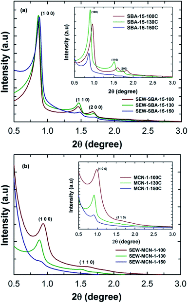
SBA-15 materials are generally synthesised under highly acidic conditions with a continuous stirring mode. However, this procedure offers SBA-15 with an irregular rod shaped morphology. In order to obtain SBA-15 with a highly regular rod shaped morphology with uniform size in length and width, the materials were synthesized under static mode. In addition, the synthesis temperature was increased to tune the pore diameter of the SBA-15 materials. The as-synthesized samples were washed with ethanol in order to remove the polymeric surfactant or structure directing agents from the pore channels. The structural order of these materials (SEW-SBA-15 templates) with different pore diameters was compared with that of mesoporous silica SBA-15 templates prepared by the calcination route under static conditions and with different pore diameters prepared are given in Fig. 1a and the inset. Fig. 1a shows the low angle powder XRD patterns of SEW-SBA-15-T (T = 100, 130 and 150 °C) in comparison to the calcined SBA-15-TC (T = 100, 130 and 150 °C, C denotes calcination) shown in the inset. All the three silica templates SEW-SBA-15-T exhibit several low angle peaks which are indexed as (100), (110) and (200) reflection planes on a 2D hexagonal lattice with a p6mm symmetry. These peaks are characteristics of the SBA-15 silica template and in agreement with previous reports in the literature.35,36Further, as the synthesis temperature is increased from 100 to 150 °C, the peaks are shifted towards higher angles after the ethanol washing. More precisely, the d-spacing and cell constant values show a decreasing trend with increasing hydrothermal synthesis temperature. This observation is quite contrary to what we have seen in previous reports for pore expanded SBA-15 silica templates prepared via the typical calcination route (inset, Fig. 1a).26,27,36 The difference in the XRD patterns of the ethanol washed SEW-SBA-15-T and calcined SBA-15-TC could be attributed to the incomplete removal of the organic surfactant or a slight disintegration of the primary mesochannels due to ethanol washing.
It is known that calcination of as-synthesized mesoporous silica prepared via the templating approach causes a complete removal of the surfactant whereas ethanol extraction can remove the surfactant anywhere between 90–92 percent.36 It was also reported that increasing the hydrothermal treatment temperature results in a partial loss of the mesostructure which is manifested in the form of reduced and different diffraction peak intensities. However, the well-shaped primary and higher order reflections and the high intensity of the peaks of ethanol washed samples reveal that they are highly ordered and the structure of the materials was not affected. It is also interesting to note that the intensities of the diffraction peaks and peak positions are nearly the same for the samples prepared at different temperatures, suggesting that all the three materials have similar structural order and increasing the synthesis temperature has a little impact on the overall structural order of the samples after washing with ethanol. These results suggest that the removal of the surfactant by the ethanol washing procedure is quite effective without affecting the structural order and found to be an efficient and alternative method for the synthesis of SBA-15 materials without calcination.36,37
MCN materials with different pore diameters and a controlled rod shaped morphology were prepared by using these ethanol washed mesoporous silica templates as templates. The structural order of the materials was analysed by powder X-ray diffraction. Fig. 1b shows the XRD patterns of SEW-MCN-1-T samples prepared from SEW-SBA-15-T silica templates as a template via a nanocasting technique. As can be seen, SEW-MCN-100 and SEW-MCN-130 show a sharp peak and a few higher order reflections which are similar to those present in the silicate template. This result firmly confirms that these samples have an ordered structure and the replication process from the silica template to the carbon nitride is successful.
Similar results were obtained when SBA-15 prepared under static synthesis conditions via the calcination route was used as a template for the synthesis of MCN-1-TC.3 However, SEW-MCN-1-150 exhibits a broad main peak without any higher order reflections, indicating a significant loss in the structural order of this sample. It should also be noted that the main peak shifts towards a higher angle, revealing a low d-spacing and unit cell constant of the material. This might be due to either partial disorientation of the primary mesochannels of the template used or the incomplete filling of the large mesopores and micropores with the C and N precursors. Similarly, SEW-MCN-1-130 has a lower intensity compared to SEW-MCN-1-100. Interestingly, a comparison of the SEW-MCN-1-T samples with MCN-1 prepared by the conventional calcination route (MCN-1-TC samples in the inset of Fig. 1b) shows a striking similarity in the XRD patterns which indicates that the ethanol washed samples are proved to be the best templates even without any calcination process for the preparation of MCN materials.
3.2 Nitrogen adsorption–desorption
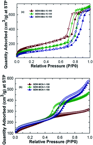
Fig. 2a shows the nitrogen adsorption isotherms for SEW-SBA-15-T samples. All the three samples show a type IV isotherm which as per the IUPAC convention suggests the mesoporous nature of the materials. The isotherms also exhibit H1 hysteresis loop typically associated with the SBA-15 kind of silica template with uniform and cylindrical pores. The amount of nitrogen adsorbed and the shape of the capillary condensation steps in the isotherms of the SEW-SBA-15-T samples clearly reveal that the pores are formed after washing with ethanol and available for the effective pore filling of C and N precursors of the templated synthesis of MCN. Further, a shift in the capillary condensation step towards higher relative pressure is clearly observed when the synthesis temperature is increased from 100 °C to 150 °C, suggesting an increase in pore diameter with increasing hydrothermal treatment temperature. This observation is also supported by the value of the pore diameter (9.12 to 11.2 nm) obtained from BJH pore size distribution (ESI, Fig. 1Sa†). On the other hand, the BET specific surface area of the SEW-SBA-15-T samples shows a decreasing trend. SEW-SBA-15-100 shows the highest surface area among the silica templates whereas SEW-SBA-15-150 exhibits the lowest surface area as shown in Table 1. A similar trend in variation of the BET surface area with increasing hydrothermal temperature was also observed for calcined SBA-15-TC samples.3| Sample | a 0 (nm) | d (nm) | Micro SA (m2 g−1) | Meso SA (m2 g−1) | BET SA (m2 g−1) | PVmicro (cm3 g−1) | PVtotal (cm3 g−1) | PD (nm) | CO2 adsorbed (mmol g−1) |
|---|---|---|---|---|---|---|---|---|---|
| a a 0 = unit cell parameter; d = d spacing; SA = surface area; PV = pore volume; PD = pore diameter; micro = microporous; meso = mesoporous. | |||||||||
| SEW-SBA-15-100 | 12.0 | 10.4 | 15 | 582 | 597 | — | 1.03 | 9.12 | 13.2 |
| SEW-SBA-15-130 | 11.7 | 10.2 | 14 | 421 | 435 | — | 1.10 | 10.5 | 10.2 |
| SEW-SBA-15-150 | 11.5 | 10.0 | 12 | 315 | 327 | — | 1.04 | 11.2 | 9.7 |
| SEW-MCN-1-100 | 10.9 | 9.46 | 39 | 557 | 596 | 0.013 | 0.49 | 2.8 | 11.6 |
| SEW-MCN-1-130 | 10.6 | 9.20 | 195 | 460 | 655 | 0.085 | 0.72 | 4.4 | 15.4 |
| SEW-MCN-1-150 | 11.8 | 10.3 | 178 | 460 | 638 | 0.077 | 0.89 | 5.7 | 13.0 |
As expected, the calcined SBA-15-TC samples have registered a larger BET surface area as compared to that of SEW-SBA-15-T. This is attributed to the fact that the high temperature calcination process supports a complete removal of the organic structure-directing agent whereas with ethanol extraction it is possible to remove only about 90% of the organic surfactant.3,36 These organic impurities partially cover the surface of the silica walls that significantly decrease the specific surface area of the samples. It is also surmised that the incomplete condensation of the silanol groups on the walls of the ethanol washed samples increases both the wall thickness and the bulk density of the samples which are also expected to affect the specific surface area of the samples as shown in the ESI, Table 1S.† This is also reflected in the specific pore volume of the ethanol washed silica templates that show the same trend as that for the calcined SBA-15-TC samples.3 It is also interesting to note that the micropore area of the samples decreases as well when the synthesis temperature is increased. This could be one of the reasons for the loss of the structural order of the SEW-MCN-1-150 sample as the presence of the micropores are key to cross-link the formed CN rods along the mesochannels of the template.
The nitrogen adsorption–desorption isotherms for the SEW-MCN-1-T samples are shown in Fig. 2b. It can be easily inferred that the MCN samples SEW-MCN-1-T also exhibit a type IV isotherm and the capillary condensation step occurs at different and higher relative pressure indicating that these materials have large and different pore diameters. The textural parameters of SEW-MCN-1-T samples are shown in Table 1. As expected, the pore diameter increases from 2.8 nm to 5.7 nm with the increase in the pore diameter of the silica template SEW-SBA-15-T (ESI, Fig. 1Sb†). A huge shift in the condensation step in the isotherm of SEW-MCN-1-150 is observed. This reveals that the pore diameter of the templates dictates the pore diameter of the final MCN materials. The reason for the expansion of the pore diameter of the MCN samples prepared with SEW-SBA-15-150 could be due to incomplete filling of the C and N precursors in the mesopore channels of the template. The BET surface area shows an increasing-decreasing trend and a similar trend is seen for the micropore volume. The total pore volume however increases progressively with increasing hydrothermal synthesis temperature of the templates.
Among the samples prepared, SEW-MCN-1-130 shows the highest surface area and micropore volume and a reasonable pore diameter and total pore volume. The highest specific surface area of SEW-MCN-1-130 could be due to the presence of large number of micropores that are formed possibly due to the incomplete condensation of the C and N precursors inside the mesochannels. On the other hand, the lowest surface area of SEW-MCN-1-150 could be attributed to the partial loss of structural order in the sample due to the disorder in the primary mesochannels in the corresponding silica template and poor interconnection between the primary mesochannles through micropores. However, all the materials show reasonable specific surface area and large pore volumes but the properties of these materials are clearly related with the structural features and the textural properties of the templates. All these results suggest a successful replication of the mesoporous structure of the template SEW-SBA-15-T to the corresponding carbon nitride SEW-MCN-1-T and a clear demonstration of using uncalcined SBA-15 for the preparation of MCN nanostructures with tuneable pore diameters, specific surface area and pore volumes.
3.3 SEM and TEM microscopy
The morphology and surface topology of the SEW-MCN-1-T samples were investigated using HR-SEM and HR-TEM microscopy. As noted earlier, morphology has a direct bearing on the textural properties of the materials which in turn determines the CO2 adsorption properties of the materials. For controlling the morphology of the MCN materials, it is essential to control the morphology of the templates which is then replicated to the carbon nitride. Vinu et al. recently demonstrated the synthesis of rod shaped MCN hybrid materials by employing static conditions. In this work, we employed the same technique but with uncalcined mesoporous silica templates.3Fig. 3d–f show the HR-SEM images of the SEW-MCN-T samples in comparison to SEW-SBA-15-T (Fig. 3a–c).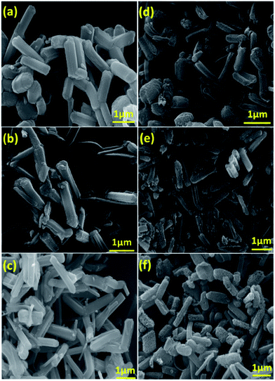 | ||
| Fig. 3 SEM images of (a) SEW-SBA-15-100; (b) SEW-SBA-15-130; (c) SEW-SBA-15-150; (d) SEW-MCN-1-100; (e) SEW-MCN-1-130; (f) SEW-MCN-1-150. | ||
From the SEM images, it is clear that the silica templates SEW-SBA-15-T have distinct and uniform rod shaped particles. The rod shaped morphology results because of the static conditions employed during the synthesis of the templates. However, the size of the single particles depends on the synthesis temperature of the template and consequently the SEW-SBA-15-T samples have rod shaped particles but of different sizes. From Fig. 3d–f, it can be easily inferred that the rod shaped morphology of the silica template is successfully replicated into the corresponding rod shaped morphology of the carbon nitride particles. Since the templates have particles of different sizes, the same is replicated to the corresponding carbon nitride. Among the three samples, the SEW-MCN-1-130 sample has particles of uniform length which are neatly dispersed without any cross-linking. These results are also consistent with the data obtained from the nitrogen adsorption and XRD analysis.
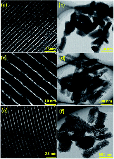
The well-ordered morphology is also one of the reasons for the highest specific surface area of the sample. The structural order and the morphology of both the templates and SEW-MCN-T samples were also analysed by HRTEM. Fig. 4a–f show the low and high resolution TEM images of the SEW-MCN-1-T samples. All the three samples have well defined mesochannels running parallel to each other clearly showing the presence of long range order which is further supported by the XRD and N2 adsorption–desorption results. The TEM images further confirm the rod shaped morphology of the particles.
3.4 X-ray photoelectron spectroscopy (XPS)
The nature and co-ordination of C and N atoms in the SEW-MCN-1-T samples were investigated with XPS spectroscopy. The surface atomic composition of the samples was estimated with the survey scan. As shown in the ESI, Fig. 2Sa,† all three samples primarily contain C and N with a trace amount of O as shown in the ESI, Table 2S.† The C and N composition of SEW-MCN-1-100 and SEW-MCN-1-130 is almost similar but a higher N content is observed for SEW-MCN-1-150. The average C, N and O atomic percentage in the samples closely resembles our very recent work.3 The absence of the Si peak in the survey spectrum suggests that the prepared samples are free from the porous silica template and the structure mainly comes from the CN framework, not from the porous silica template. This further confirms that the replication process was successful. The survey spectrum of all the three samples shows the peaks of C, N and O at almost identical BE values, indicating that these samples are chemically identical in terms of the surface distribution of C and N atoms. The trace quantity of O in the sample is ascribed to the ethanol wash step after the removal of silica with HF or it could also have come from the adsorption of atmospheric water vapour or CO2.The bonding and chemical environment was further investigated with high resolution C1s and N1s scans and the results are shown in the ESI, Fig. 2Sb and c.† The C1s high resolution scan for the SEW-MCN-1-100 sample was deconvoluted into 4 peaks with BE values 284.4 eV, 285.1 eV, 287.3 eV and 289.3 eV as shown in the ESI, Fig. 2Sb.† These values are in close agreement with previously reported results.3,4 The lowest energy contribution of the C1s peak is attributed to the sp2 hybridised carbon which mainly comes from the graphitic sites of the CN framework whereas the highest energy contribution can be ascribed to the aromatic carbon that is linked with the nitrogen functional groups outside the ring. On the other hand, the peaks at 285.1 and 287.3 eV are attributed to graphitic carbon bonded with the N inside the aromatic ring and with multiple nitrogen atoms, respectively. It is interesting to note that C from the surfactant of the uncalcined template does not make any changes in the bonding and coordination with the N in the CN framework. It is assumed that the trace amount of the surfactant which was still present in the template during the preparation of MCN was completely decomposed during the carbonization process. These results clearly reveal that the ethanol washed samples do not make any difference in the nature of the bonding characteristics of MCN nanostructures. The N1s spectra were also deconvoluted into three peaks with BE values, 398.2 eV, 399.6 eV and 400.6 eV, as shown in Fig. 2Sc.† The lowest and the highest energy contributions are attributed to the bonding of N with one and three sp2 hybridised carbons of graphitic carbons respectively whereas the peak at 399.6 eV is ascribed to the bonding of N and C inside the aromatic framework. The content of carbon and nitrogen in the samples was also investigated using the CNS analyser and the values are indicated in the ESI, Table 2S.† The composition of the samples is similar to that obtained from XPS survey spectra. As noted earlier, the SEW-MCN-1-150 sample has the highest nitrogen content among the samples studied. This might be due to the higher degree of polymerization between the C and N precursors inside the template with the largest pore size.
3.5 Near edge X-ray absorption fine structure (NEXAFS)
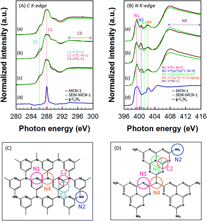
A synchrotron based NEXAFS technique was used to further investigate the chemical bonding in SEW-MCN-1-T samples. For the purpose of comparison, NEXAFS data were also recorded for MCN-1-T-C (calcined) samples and g-C3N4 prepared from dicyandiamide. The carbon K-edge spectra of SEW-MCN-1-T and MCN-1-T-C samples show the presence of characteristic resonances of carbon nitride: π*C![[double bond, length as m-dash]](https://www.rsc.org/images/entities/char_e001.gif) C (C1) at 286.0 eV, π*C–N–C (C2) at 288.0 eV, and long range σ*C–C (C3) resonance which occurs over the range 292–300 eV (Fig. 5A(a–c)). The nitrogen K-edge spectra show four typical π* resonances occurring at photon energies of 399.3, 400.5, 401.3 and 402.3 eV, which correspond to aromatic C–N–C coordination in one tri-s-triazine heteroring (N1), terminal C–N–H (N2) bond, graphitic three-fold nitrogen atom N–3C (N3), and sp3 N–3C bridging among the three tri-s-triazine moieties (N4) respectively.37,38 The long range σ*N–C (N5) resonance occurs over the range 405–416 eV (Fig. 5B(a–c)). Fig. 5C and D show the possible theoretical structure of MCN-1-T/SEW-MCN-1 and g-C3N4 respectively with different C and N atoms present in different bonding environments. It is interesting to note that MCN-1 materials do not contain any triazine moieties. Apart from this, the results for MCN-1/SEW-MCN-1 are almost similar to those of g-C3N4.
C (C1) at 286.0 eV, π*C–N–C (C2) at 288.0 eV, and long range σ*C–C (C3) resonance which occurs over the range 292–300 eV (Fig. 5A(a–c)). The nitrogen K-edge spectra show four typical π* resonances occurring at photon energies of 399.3, 400.5, 401.3 and 402.3 eV, which correspond to aromatic C–N–C coordination in one tri-s-triazine heteroring (N1), terminal C–N–H (N2) bond, graphitic three-fold nitrogen atom N–3C (N3), and sp3 N–3C bridging among the three tri-s-triazine moieties (N4) respectively.37,38 The long range σ*N–C (N5) resonance occurs over the range 405–416 eV (Fig. 5B(a–c)). Fig. 5C and D show the possible theoretical structure of MCN-1-T/SEW-MCN-1 and g-C3N4 respectively with different C and N atoms present in different bonding environments. It is interesting to note that MCN-1 materials do not contain any triazine moieties. Apart from this, the results for MCN-1/SEW-MCN-1 are almost similar to those of g-C3N4.
3.6 CO2 adsorption
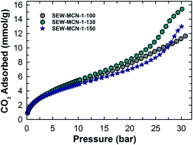
We recently reported the CO2 adsorption capacity of pore tuned and morphology controlled MCN hybrid materials.3 These materials showed a very high and promising adsorption capacity under a different pressure range of 0 to 30 bar and temperature conditions from 0 to 25 °C and excellent recycling properties, all of which indicated its suitability as an adsorbent for CO2 on a commercial scale. However, from energy economics point of view, the overall process is extremely energy and time intensive and hence unappealing. The focus of this work was to make the high-temperature calcination process less demanding on a time-saving and energy-efficient scale and still have nearly the same or better CO2 adsorption capacity thereby rendering MCN materials a suitable and attractive adsorbent for CO2.The materials prepared in this work were used as adsorbents at a very high pressure of upto 30 bar and different temperatures 0, 10 and 25 °C. Fig. 6 shows the CO2 adsorption isotherms for SEW-MCN-1-T samples recorded at 0 °C. Among the samples studied, SEW-MCN-1-130 registered the highest CO2 adsorption capacity of 15.4 mmol g−1 at 0 °C and 30 bar whereas SEW-MCN-1-100 and SEW-MCN-1-150 show capacities of 11.6 and 13 mmol g−1 respectively under identical temperature and pressure conditions as summarized in Table 1.
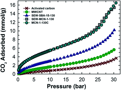
The higher adsorption capacity of SEW-MCN-1-130 is mainly attributed to the higher specific surface area together with the micropore area of this sample. It is interesting to note that the adsorption capacity of the prepared MCN is almost similar to that of MCN prepared from calcined SBA-15 under the same adsorption conditions, revealing the perfect templating properties of ethanol washed and uncalcined SAB-15 (Fig. 7).3 However, if we compare the CO2 adsorption capacity of these two samples taking into consideration of heat energy and time duration involved, there is no doubt that from the commercial point of view, the SEW-MCN-1-130 sample has an edge over MCN prepared from the calcined counterpart.
It is also important to emphasize here that SEW-MCN-1-T and MCN-1-TC materials are quite similar from structural, compositional and chemistry point of view with the exception of textural properties of the two materials since the method for removal of an organic structure-directing agent does have a strong effect on the final textural properties of the materials. As discussed earlier, calcined MCN-1-TC samples have slightly better textural parameters as compared to ethanol washed materials, and this difference essentially explains the slightly reduced CO2 adsorption capacity registered by SEW-MCN-1-T samples.3
The effect of temperature on the adsorption capacity is clearly evident from Fig. 3S(a–c) and ESI, Table 3S.† From the data in Table 3S,† it follows that lower analysis temperature is favourable for higher CO2 uptake and as the analysis temperature is increased, the CO2 uptake behaviour of materials plummets significantly suggesting a strong temperature dependence of adsorption capacity of these materials. The strength of interaction between the CO2 adsorbate and MCN adsorbent is quantified in terms of the isosteric heat of adsorption.
Fig. 8 shows the variation of isosteric heat of adsorption of SEW-MCN-1-T samples and their comparison with MCN-1-TC and MCN-7-130 samples. From Fig. 8, it is clear that among SEW-MCN-1-T samples, although SEW-MCN-1-130 shows a higher CO2 adsorption owing to its highest surface area, well defined structural order and uniform rod shaped morphology together with well-defined mesostructure, it is the SEW-MCN-1-150 samples which show a higher isosteric heat of adsorption (ESI, Table 4S†).
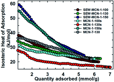 | ||
| Fig. 8 Variation of isosteric heat of adsorption of SEW-MCN-1-T samples with the quantity of CO2 adsorbed and its comparison with other materials. | ||
Interestingly, we found a similar trend for the case of MCN-1-Ts samples as well in our previous work. The reason for the stronger adsorbent–adsorbate interaction and hence higher isosteric heat for SEW-MCN-1-150 could be attributed to the availability of large pores in the SEW-MCN-1-150 sample which provide an easy access to CO2 molecules. Further, N% per unit surface area is also the highest for SEW-MCN-1-150 samples (ca. 3.2%) which facilitates multilayer CO2 adsorption resulting in a stronger adsorbate–adsorbent interaction.
As well documented in the literature, it is clear that textural parameters together with inbuilt basic functional groups, structural and morphological properties are some of the controlling factors that dictate the CO2 adsorption of a material. It has been observed that materials with a higher BET surface area and pore volume tend to exhibit a higher CO2 adsorption capacity when the analysis temperature and adsorption pressure are kept the same as shown in Fig. 9. Table 5S (ESI†) shows the surface area normalized CO2 adsorption capacity of the three samples including the % nitrogen content. Among the samples, SEW-MCN-1-130 has the highest surface area and the % N content is midway between SEW-MCN-1-100 and SEW-MCN-1-150 but the CO2 adsorption capacity per unit surface area is still the highest for SEW-MCN-1-130 samples. The above normalized values indicate that the N content also influences the overall CO2 adsorption however, between the surface area and N content, the surface area has an overwhelming influence on the CO2 adsorption capacity. As noted earlier, a well-ordered and uniform morphology results in a higher surface area for the SEW-MCN-1-130 sample which in turn is responsible for the higher CO2 adsorption capacity of the SEW-MCN-1-130 sample in comparison to the other two samples. Thus an indirect co-relation exists between the well-ordered morphology, surface area and CO2 adsorption capacity. Further it is confirmed that a combination of the surface area and nitrogen content dictates the overall CO2 adsorption capacity of SEW-MCN-1-T samples with the major contribution related to the surface area and minor contribution attributed to nitrogen containing basic functional groups –NH and –NH2. The ethanol washed SEW-MCN-1-T samples also exhibit excellent recycling properties and do not give in to the enormous compressive forces resulting from high gas pressure used for adsorption applications. Besides, SEW-MCN-1-T samples could be easily regenerated by applying controlled heating at 200–250 °C under vacuum for 6–10 h. The above presentation and the accompanying discussion strongly suggests that MCN with a definite morphology and excellent textural and structural properties could be easily synthesized without expending a lot of energy and time and improving the prospects of MCN as a suitable adsorbent for CO2 capture.
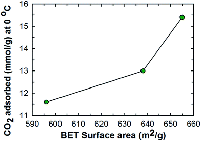 | ||
| Fig. 9 Relation between the specific surface area and the CO2 adsorption capacity of SEW-MCN-1-T samples. | ||
4. Conclusions
In this work, we reported for the first time a calcination-free energy- and time-saving synthesis of ordered MCN materials with a rod shaped morphology and evaluated their CO2 uptake behaviours. These MCN materials exhibited excellent textural parameters, highly ordered structure and a uniform particle morphology and their textural parameters are at par with MCN materials prepared by the conventional calcination route. We also demonstrated that it is possible to synthesize silica templates with different pore diameters without taking recourse to an extremely expensive and energy intensive high temperature calcination step. Moreover, the morphology of these materials was controlled by adopting a static synthesis protocol for the mesoporous silica templates. The pore size of the replicated MCN materials could be also varied easily from 2.8 nm to 5.7 nm without requiring any additional steps but by varying the synthesis temperature of the templates. The MCN materials prepared via the ethanol extraction route were employed as CO2 adsorbents under different temperature and pressure conditions. Interestingly, the CO2 uptake capacity of MCN materials prepared by ethanol extraction (ca. 15.4 mmol g−1 at 30 bar and 0 °C) did not show much aberration from those prepared by the calcined SBA-15 templates. Interestingly, the CO2 adsorption capacity of the MCN prepared in this work was found to be higher than the cage type 3D MCN (ca. 13.5 mmol g−1 at 30 bar and 0 °C). This could be attributed to a number of factors such as a higher surface area, pore volume, highly ordered structure and long range mesoporosity besides the inherent basic functional sites such as –NH and –NH2 groups which contribute in anchoring the acidic CO2 gas molecules to the surface of the MCN materials. We also demonstrated that MCN materials possess a very high structural integrity and can withstand high pressure without causing any structural damage. Further, these MCN materials could be regenerated easily and reused without any significant change in their CO2 uptake behaviour. The successful synthesis and excellent CO2 uptake capacity of these MCN materials would provide a strong impetus for environmental-friendly and low-cost large scale production of MCN as adsorbents for CO2 capture and storage. From an industrial application point of view, the selectivity of an adsorbent for a mixture of gases for example flue gases mainly contain CO2 and N2 and sometimes CH4 is an important criteria that must be fulfilled. In a vast majority of reports in the literature, pure component adsorption isotherms are used to calculate the selectivity assuming the molecules CO2, N2 and CH4 have negligible interaction.24,39,40 However, in a more realistic situation, adsorption of a gaseous mixture containing two or more molecules would involve a significant interaction between molecules of different gases and the nature of interaction between molecules of same gas will also be affected. These factors must be accounted for when employing an adsorbent for commercial applications involving a mixture of two or more gases.Acknowledgements
One of the authors A. Vinu acknowledges the Australian Research Council for the Future Fellowship and SABIC for the research grants. The authors also acknowledge the support of Australian Synchrotron for the soft X-ray beam time.References
- K. S. Lakhi, D. H. Park, K. Al-Bahily, W. Cha, B. Viswanathan, J. H. Choy and A. Vinu, Chem. Soc. Rev., 2017, 46, 72–101 RSC.
- R. Sanz, G. Calleja, A. Arencibia and E. S. Sanz-Perez, Microporous Mesoporous Mater., 2012, 158, 309–317 CrossRef CAS.
- K. S. Lakhi, A. V. Bhaskar, J. S. M. Zaidi, S. S. Al-Deyab, M. El-Newehy, J.-H. Choy and A. Vinu, RSC Adv., 2015, 5, 40183–40192 RSC.
- K. S. Lakhi, W. S. Cha, S. Joseph, B. J. Wood, S. S. Aldeyab, G. Lawrence, J. H. Choy and A. Vinu, Catal. Today, 2015, 243, 209–217 CrossRef CAS.
- X. Yan, L. Zhang, Y. Zhang, K. Qiao, Z. Yan and S. Komarneni, Chem. Eng. J., 2011, 168, 918–924 CrossRef CAS.
- X. Zhu, P. C. Hillesheim, S. M. Mahurin, C. Wang, C. Tian, S. Brown, H. Luo, G. M. Veith, K. S. Han, E. W. Hagaman, H. Liu and S. Dai, ChemSusChem, 2012, 5, 1912–1917 CrossRef CAS PubMed.
- S. Choi, J. H. Drese and C. W. Jones, ChemSusChem, 2009, 2, 796–854 CrossRef CAS PubMed.
- M. A. Chari, D. Shoba, E. R. Kenawy, S. S. Al-Deyab, B. V. S. Reddy and A. Vinu, Tetrahedron Lett., 2010, 51, 5195–5199 CrossRef CAS.
- P. Srinivasu, S. Alam, V. V. Balasubramanian, S. Velmathi, D. P. Sawant, W. Bohlmann, S. P. Mirajkar, K. Ariga, S. B. Halligudi and A. Vinu, Adv. Funct. Mater., 2008, 18, 640–651 CrossRef CAS.
- Z. Huang and S. Che, Bull. Chem. Soc. Jpn., 2015, 88, 617–632 CrossRef CAS.
- Y. Zhao, K. X. Yao, B. Teng, T. Zhang and Y. Han, Energy Environ. Sci., 2013, 6, 3684–3692 CAS.
- R. Serna-Guerrero, Y. Belmabkhout and A. Sayari, Chem. Eng. J., 2010, 158, 513–519 CrossRef CAS.
- Y. Belmabkhout, R. Serna-Guerrero and A. Sayari, Chem. Eng. Sci., 2010, 65, 3695–3698 CrossRef CAS.
- P. J. E. Harlick and A. Sayari, Ind. Eng. Chem. Res., 2006, 45, 3248–3255 CrossRef CAS.
- W. J. Son, J. S. Choi and W. S. Ahn, Microporous Mesoporous Mater., 2008, 113, 31–40 CrossRef CAS.
- N. P. Wickramaratne, J. Xu, M. Wang, L. Zhu, L. Dai and M. Jaroniec, Chem. Mater., 2014, 26, 2820–2828 CrossRef CAS.
- D. Li, W. B. Li, J. S. Shi and F. W. Xin, RSC Adv., 2016, 6, 50138–50143 RSC.
- J. Fujiki and K. Yogo, Chem. Commun., 2016, 52, 186–189 RSC.
- J. Gong, H. Lin, M. Antonietti and J. Yuan, J. Mater. Chem. A, 2016, 4, 7313–7321 CAS.
- M. Nandi, K. Okada, A. Dutta, A. Bhaumik, J. Maruyama, D. Derks and H. Uyama, Chem. Commun., 2012, 48, 10283–10285 RSC.
- S. Feng, W. Li, Q. Shi, Y. Li, J. Chen, Y. Ling, A. M. Asiri and D. Zhao, Chem. Commun., 2014, 50, 329–331 RSC.
- X. Bing, Y. Wei, M. Wang, S. Xu, D. Long, J. Wang, W. Qiao and L. Ling, J. Colloid Interface Sci., 2017, 488, 207–217 CrossRef CAS PubMed.
- G. Sethia and A. Sayari, Energy Fuel, 2014, 28, 2727–2731 CrossRef CAS.
- V. Chandra, S. U. Yu, S. H. Kim, Y. S. Yoon, D. Y. Kim, A. H. Kwon, M. Meyyappan and K. S. Kim, Chem. Commun., 2012, 48, 735–737 RSC.
- M. Sevilla, J. B. Parra and A. B. Fuertes, ACS Appl. Mater. Interfaces, 2013, 5, 6360–6368 CAS.
- A. Vinu, K. Ariga, T. Mori, T. Nakanishi, S. Hishita, D. Golberg and Y. Bando, Adv. Mater., 2005, 17, 1648–1652 CrossRef CAS.
- A. Vinu, Adv. Funct. Mater., 2008, 18, 816–827 CrossRef CAS.
- S. S. Talapaneni, S. Anandan, G. P. Mane, C. Anand, D. S. Dhawale, S. Varghese, A. Mano, T. Mori and A. Vinu, J. Mater. Chem. A, 2012, 22, 9831–9840 RSC.
- K. Sakaushi and M. Antonietti, Bull. Chem. Soc. Jpn., 2015, 88, 386–398 CrossRef CAS.
- L. Xiao, J. Li, H. Jin and R. Xu, Microporous Mesoporous Mater., 2006, 96, 413–418 CrossRef CAS.
- M. H. Yuan, L. Wang and R. T. Yang, Langmuir, 2014, 30, 8124–8130 CrossRef CAS PubMed.
- R. V. Grieken, G. Calleja, G. D. Stucky, J. A. Melero, R. A. Garcia and J. Iglesias, Langmuir, 2003, 19, 3966–3973 CrossRef.
- C. Pirez, K. Wilson and A. F. Lee, Green Chem., 2014, 16, 197–202 RSC.
- L. M. Yang, Y. J. Wang, G. S. Luo and Y. Y. Dai, Microporous Mesoporous Mater., 2005, 81, 107–114 CrossRef CAS.
- D. Zhao, J. Feng, Q. Huo, N. Melosh, G. H. Fredrickson, B. F. Chmelka and G. D. Stucky, Science, 1998, 279, 548–552 CrossRef CAS PubMed.
- A. Olea, E. S. Sanz-Perez, A. Arencibia, R. Sanz and G. Calleja, Adsorption, 2013, 29, 589–600 CrossRef.
- Y. Zheng, Y. Jiao, Y. Zhu, L. H. Li, Y. Han, Y. Chen, A. Du, M. Jaroniec and S. Z. Qiao, Nat. Commun., 2014, 5, 3783 Search PubMed.
- R. Arrigo, M. E. Schuster, S. Abate, G. Giorgianni, G. Centi, S. Perathoner, S. Wrabetz, V. Pfeifer, M. Antonietti and R. Schlögl, ACS Catal., 2016, 6, 6959–6966 CrossRef CAS.
- K. V. Kumar, K. Preuss, L. Lu, Z. X. Guo and M. M. Titirici, J. Phys. Chem. C, 2015, 119, 22310–22321 CAS.
- A. A. Niya, T. E. Rufford and Z. Zhu, Energy Fuel, 2016, 30, 7298–7309 CrossRef.
Footnote |
| † Electronic supplementary information (ESI) available. See DOI: 10.1039/c6ta10716h |
| This journal is © The Royal Society of Chemistry 2017 |

