 Open Access Article
Creative Commons Attribution 3.0 Unported Licence
Switchable bumps of a bead-embedded elastomer surface with variable adhesion†
T.
Ohzono
 and
K.
Teraoka
Research Institute for Sustainable Chemistry, AIST, 1-1-1 Higashi, Tsukuba, 305-8565, Japan. E-mail: ohzono-takuya@aist.go.jp; ok-teraoka@aist.go.jp
First published on 14th November 2017
Abstract
An extremely simple structural design of a composite material composed of an elastomer sheet and hard beads embedded at the surface is proposed to realize a shape-tunable surface; it reversibly forms bumps/undulations in response to in-plane tensile strain applied to the surface. Tribological properties such as adhesion therefore become switchable.
The surface structures of soft materials, such as rubber and plastics, are critical for their tribological properties. A variety of surface structures of elastomeric materials have been proposed to control both adhesion and friction1–3 in many applications, including grips on tools, robot hands, and sports equipment. Some functional surfaces for such applications show a fundamental need for on-demand tuning of friction and adhesion forces.4–6 Such tunability may be realized by systems in which some external “triggers” cause a variation in the adhesion and friction forces associated with a material. Since adhesion and friction largely depend on the surface structure and the chemistry of the surface material, introducing their topological/chemical switchability may satisfy the need for tribological tunability. In previous studies, we and other groups have made developments via the former strategy; creating shape-tuneable surfaces, using wrinkles7–11 with a wavy topography, which spontaneously appear because of the strain-induced buckling of a hard skin layer formed on a soft elastic substrate. The use of shape-tuneable wrinkles12–21 has demonstrated that friction22–24 and adhesion25 can be switched depending on the strain applied to the wrinkle substrate. Although various structural designs that realize nonlinear shape-tunability26,27 exist, designs that target the tribological requirements have not been proposed, other than the wrinkle system.
Herein, we present a new and extremely simple design of a shape-tuneable surface, in which the surface forms bumps in response to tensile strain. The structure is composed of spherical glass beads that are embedded near the surface of a silicone elastomeric substrate. The relationship between the structure and the applied strain is evaluated and discussed. Moreover, the variable adhesion properties of the shape-tuneable surface are also demonstrated.
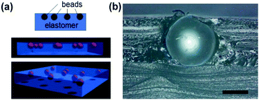
Fig. 1a shows a schematic of the bead-embedded poly(dimethyl siloxane) (PDMS, Sylgard 184, Toray-Dow) elastomer. To fabricate the structure, the glass beads (diameter D = 0.1–1.6 mm) were placed on the uncured PDMS sol with a thickness (t0) of ∼3 mm on a flat glass substrate (used only as a template) and cured at 303 K for 48 h. Due to the higher density of the glass beads than that of PDMS sol, the beads sediment and reach the flat glass surface in tens of minutes. After curing, the PDMS sheet was peeled off the glass substrate and the bead-embedded elastomer sheet was obtained. The side that had contacted the flat glass template is the surface of interest.
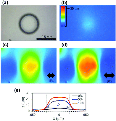
The cross section of the composite elastomer is shown in Fig. 1b, and it indicates that the bead is placed in the proximity of the interface. Fig. 2a shows a top view of the composite elastomer, where the embedded bead is visible through the transparent PDMS. Without tensile strain (ε = 0%), the surface is almost flat (Fig. 2b and e). Under tensile strain, a bump forms over the bead. The height, δ, which is defined as the height at the top of the bump with reference to the point distant from the center as shown in the inset of Fig. 3a, increases with ε (Fig. 2c–e).
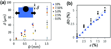
To clarify the effect of D on this phenomenon, samples embedded with beads of different D ranging from 0.1 to 1.5 mm were evaluated at different ε. Fig. 3a shows the plots of δ vs. D at different ε, indicating their linear relationship. In Fig. 3b, the same data set was used to plot the non-dimensional bump height normalized by the bead diameter, δ/D, vs. ε. Although the data slightly scatter, δ/D is almost independent of the size of the beads and linearly depends only on ε, i.e., δ is proportional to both D and ε; δ ∝ Dε.
The bump formation can be explained as follows. Under the uniaxial tensile strain ε (positive value for tensile strain), the base sheet is primarily expanded in the strain direction and simultaneously contracts in the perpendicular directions to conserve total volume, thinning the sheet as a result. The thickness of the base sheet, t, should decrease to t = t0(1 − νε), where ν is the Poisson's ratio of the elastic base, ∼0.5. Since the Young's modulus of the embedded glass beads (∼100 GPa) is much higher than that of the elastomeric base sheet (∼1 MPa), the glass beads behave as a rigid body under the tensile strain applied to the base sheet. Therefore, the rigid beads resist the expansion and associated perpendicular contraction. Thus, base sheet thickness around beads decreases such that the bumps form at the beads.
Since the bead ranges D in the sheet thickness direction, the thickness at the bead tb becomes tb = D + (t0 − D)(1 − νε) = t0(1 − νε) + νDε = t + νDε. Then, the ideal height difference, δ, between the peak of a bump and the position far from the bead should roughly obey the equation δ = tb − t = νDε, and thus, δ/D = νε; δ ∝ Dε. Although this discussion cannot predict the exact surface profiles, this very simple theoretical relation governing the height of the bumps corresponds well to the experimental results shown in Fig. 3. The small bump at ε = 0% may appear because of a slight shrinkage of the PDMS volume during curing.28 A similar phenomenon is known to roughen (unintentionally) the surface of thermoplastic resins reinforced with hard materials such as fiber-reinforced plastics, due to the mismatch of the thermal expansion coefficients. In our system, mechanical strain is purposely applied to induce and control the bump formation.
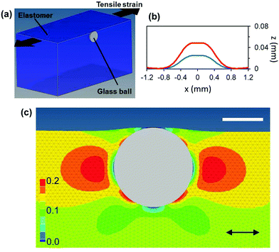
To further investigate the deformation of the elastic sheet around a bead under uniaxial strain, conventional three-dimensional (3D) finite element (FE) analysis was conducted using ABAQUAS® Standard 6.13-5. A single bead (modelled as a rigid body) with D = 1 mm was embedded in an elastomer sheet 10 × 10 × 5 mm with the Young's modulus of 1 MPa and Poisson's ratio of 0.495, as shown in Fig. 4a. The bead and the elastomer are strongly bonded. The total number of 3D elements was 578![[thin space (1/6-em)]](https://www.rsc.org/images/entities/char_2009.gif) 236 and the smaller size of the elements (0.01–0.05 mm) around the beads was used.
236 and the smaller size of the elements (0.01–0.05 mm) around the beads was used.
Fig. 4 summarizes the results obtained by the FE simulation. The simulated surface profile under strain reproduced the experimentally observed trapezoid-like bump and the height increases with ε almost linearly as expected. The values of δ/D obtained by FE simulations are also plotted in Fig. 3b, showing a good agreement with the experiments. The map of the local simple strain in the applied tensile strain in the rubber is shown in Fig. 4c. The strain is localized at both sides of the bead in the strain direction. This suggests that in the case of the weak bonding between these materials, the delamination of the elastomer from the beads may start at these locations. Indeed, at applied strain higher than 10%, we sometimes observe an air gap between a bead and the elastomer. In terms of the bump formation, the delamination has no adverse effect because it relaxes the strain in the applied strain direction and the shrinkage in the perpendicular direction increases on the side of the bead, accentuating the bump.
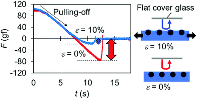
To demonstrate the ability of the present shape-tunability for controlling tribological properties, we measured the adhesion between the flat/bumped surface and a flat glass surface. For this evaluation, the beads (D = 1 mm) are randomly embedded at the elastomer surface with the area number density of ∼0.6 mm−2. Fig. 5 shows typical force curves obtained during the removal of the glass at a speed of ∼0.25 mm s−1 from the elastomer surface, at different applied strains (ε = 0 and 10%). It is clear that the adhesion on the surface with bumps is much lower than the flat state. This is simply attributed to the smaller contact area for the surface with bumps. Thus, if the area number density and/or the diameter of beads are adjusted, the change in the adhesion force would be tuned. The present system has potential as a tuneable/switchable adhesion pad.
Finally, a simple system is shown to demonstrate the switchable adhesion pad using the present bead-embedded elastomer. Fig. 6a shows a schematic of the switchable adhesion pad, which is made of a polymeric bottle that is easily-deformable by hand. The circular top of the bottle was replaced by the bead-embedded PDMS elastomer sheet. The bottle is sealed so that the elastomer sheet curves outward under the manually-squeezing-induced increased inner pressure. When the bottle is squeezed manually, an isotropic tensile strain of 3–5% can be applied to the elastomer sheet to induce the small bumps. Thus, we can control the adhesion force manually. In Fig. 6b, a series of snapshots demonstrate switchable adhesion, showing lifting and detaching a slide glass (5 g) (see also Movie 1, ESI†). Unlike the system shown in Fig. 5, in which the bead-embedded elastomer sheet is uniaxially stretched, the present system shows a non-negligible spherical curvature when the bottle is squeezed. This outward bulge with the larger radius of curvature than the bumps may also decrease the adhesion because it can also reduce the effective contact area. To show effectiveness of the small bumps on the reduction of adhesion for this system, a reference system without beads was also investigated (Fig. 6c). In this case, the glass slide was adhered even when the bottle was squeezed, proving the effective role of the small bumps on reduction of adhesion.
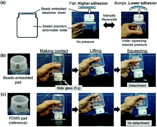 | ||
| Fig. 6 Demonstration of a switchable adhesion pad. (a) A schematic of the pad, which is made of a polymeric deformable bottle (∼250 mL). The circular top (diameter of 32 mm) of the bottle is replaced by the bead (D = 1.5 mm)-embedded PDMS elastomer sheet. The area number density of the beads is 0.35 mm−2. The bottle is sealed so that the elastomer sheet curves outward under the increased inner pressure induced by manual squeezing. The isotropic tensile strain of 3–5% can be manually applied to the elastomer sheet to induce the small bumps/undulations. (b) A series of snapshots showing switchable adhesion, showing lifting and detaching a slide glass (5 g). (c) A series of snapshots in the case of the reference PDMS pad without beads, showing that adhesion is still high enough even at the squeezed state because of the absence of small bumps. (See also Movie S1 (ESI†).). | ||
Conclusions
We have reported a very simple design of a shape-tunable elastomer surface, in which spherical beads are embedded at the surface. When the elastomeric substrate is stretched, a bump with the diameter comparable to the embedded bead size appears. The bump height scales proportionally to the applied tensile strain, which is also confirmed by FE simulation and understood by the simple model presented. Since the bump height is also linearly related to the bead diameter, the smaller bump would form by using the smaller bead, to the point that the inherent roughness matters. On such a system with smaller beads, the thickness of the skin PDMS layer on the beads, which is neglected in the present study, would become non-negligible in comparison with the bead diameter. In this case, the bump profile is expected to be dulled, and thus, the thickness parameter should be controlled for fine tuning of the bump shape. When a number of beads are embedded, the tensile strain induces undulation over the surface. Since this change in the surface topography alters the state of contact with other solid objects, this surface has potential as a new elastomer surface that can tune tribological properties on demand. For this example system, it has been shown that the adhesion is switchable depending on the applied strain. Moreover, by further exploiting the switchable property, a manually-operable switchable adhesion pad was fabricated. For more practical applications, the bead shape, number density, and patterns of beads/arrangement should be optimized to tune the adhesion properties of the bumped surface. Since both the mechanism of the present topographical change and the composite structure are extremely simple, the present system is broadly applicable toward designing tribological soft-matter interfaces with tunability, such as robot hands, grips, rubber belts, and adhesive tapes.Conflicts of interest
There are no conflicts to declare.Acknowledgements
This work was partially supported by JSPS KAKENHI Grant Number JP17K18862.Notes and references
- B. Bhushan, Philos. Trans. R. Soc., A, 2009, 367, 1445 CrossRef CAS PubMed.
- A. Jagota and C.-Y. Hui, Mater. Sci. Eng., R, 2011, 72, 253 Search PubMed.
- K. Brörmann, I. Barel, M. Urbakh and R. Bennewitz, Tribol. Lett., 2013, 50, 3 CrossRef.
- F. P. Bowden and D. Tabor, The Friction and Lubrication of Solids, Oxford University Press, New York, 1950 Search PubMed.
- E. Rabinowicz, Friction and Wear of Materials, John Wiley & Sons, New York, 2nd edn, 1995 Search PubMed.
- V. L. Popov, Contact Mechanics and Friction: Physical Principles and Applications, Springer–Verlag and Heidelberg GmbH Co. KG, Berlin, 2010 Search PubMed.
- N. Bowden, S. Brittain, A. G. Evans, J. W. Hutchinson and G. M. Whitesides, Nature, 1998, 393, 146 CrossRef CAS.
- N. Bowden, W. T. S. Huck, K. E. Paul and G. M. Whitesides, Appl. Phys. Lett., 1999, 75, 2557 CrossRef CAS.
- J. Genzer and J. Groenewold, Soft Matter, 2006, 2, 310 RSC.
- D. Y. Khang, H. Jiang, Y. Huang and J. A. Rogers, Science, 2006, 311, 208 CrossRef CAS PubMed.
- C. S. Davis and A. J. Crosby, Soft Matter, 2011, 7, 5373 RSC.
- T. Ohzono and M. Shimomura, Phys. Rev. B: Condens. Matter Mater. Phys., 2004, 69, 132202 CrossRef.
- T. Ohzono and M. Shimomura, Langmuir, 2005, 21, 7230 CrossRef CAS PubMed.
- T. Ohzono, H. Watanabe, R. Vendamme, C. Kamaga, T. Ishihara, T. Kunitake and M. Shimomura, Adv. Mater., 2007, 19, 3229 CrossRef CAS.
- T. Ohzono, H. Monobe, K. Shiokawa, M. Fujiwara and Y. Shimizu, Soft Matter, 2009, 5, 4658 RSC.
- T. Ohzono, H. Monobe, R. Yamaguchi, Y. Shimizu and H. Yokoyama, Appl. Phys. Lett., 2009, 95, 014101 CrossRef.
- T. Ohzono and H. Monobe, J. Colloid Interface Sci., 2012, 369, 1 CrossRef PubMed.
- T. Ohzono, K. Suzuki, T. Yamaguchi and N. Fukuda, Adv. Opt. Mater., 2013, 1, 374 CrossRef.
- S. Yang, K. Khare and P.-C. Lin, Adv. Funct. Mater., 2010, 20, 2550 CrossRef CAS.
- C. Cao, H. F. Chan, J. Zang, K. W. Leong and X. Zhao, Adv. Funct. Mater., 2014, 26, 1763 CrossRef CAS PubMed.
- K. Suzuki, Y. Hirai and T. Ohzono, ACS Appl. Mater. Interfaces, 2014, 6, 10121 CAS.
- K. Suzuki, Y. Hirai, M. Shimomura and T. Ohzono, Tribol. Lett., 2015, 60, 1 CrossRef CAS.
- K. Suzuki and T. Ohzono, Soft Matter, 2016, 12, 6176 RSC.
- T. Ohzono and K. Teraoka, AIP Adv., 2017, 7, 055309 CrossRef.
- Y. Rahmawan, C. M. Chena and S. Yang, Soft Matter, 2014, 10, 5028 RSC.
- T. Tallinen, J. S. Biggins and L. Mahadevan, Phys. Rev. Lett., 2013, 110, 024302 CrossRef CAS PubMed.
- G. Wu, Y. Xia and S. Yang, Soft Matter, 2014, 10, 1392 RSC.
- M. H. Madsen, N. A. Feidenhans’l, P.-E. Hansen, J. Garnæs and K. Dirscherl, J. Micromech. Microeng., 2014, 24, 127002 CrossRef CAS.
Footnote |
| † Electronic supplementary information (ESI) available: Movie 1. See DOI: 10.1039/c7sm02048a |
| This journal is © The Royal Society of Chemistry 2017 |

