 Open Access Article
Self-spreading of the wetting ridge during stick-slip on a viscoelastic surface†
S. J.
Park‡
 ab,
J. B.
Bostwick
 c,
V.
De Andrade
d and
J. H.
Je
 *a
*a
aX-ray Imaging Center, Department of Materials Science and Engineering, Pohang University of Science and Technology, 77 Cheongam-Ro, Nam-Gu, Pohang 37673, South Korea. E-mail: jhje@postech.ac.kr
bNeutron Science Division, Research Reactor Utilization Department, Korea Atomic Energy Research Institute, 111 Daedeok-Daero 989 Beon-Gil, Yuseong-Gu, Daejeon, 34057, South Korea
cDepartment of Mechanical Engineering, Clemson University, Clemson, SC 29634, USA
dX-ray Science Division, Advanced Photon Source, Argonne National Laboratory, 9700 South Cass Avenue, Argonne, IL 60439, USA
First published on 23rd October 2017
Abstract
Dynamic wetting behaviors on soft solids are important to interpret complex biological processes from cell–substrate interactions. Despite intensive research studies over the past half-century, the underlying mechanisms of spreading behaviors are not clearly understood. The most interesting feature of wetting on soft matter is the formation of a “wetting ridge”, a surface deformation by a competition between elasticity and capillarity. Dynamics of the wetting ridge formed at the three-phase contact line underlies the dynamic wetting behaviors, but remains largely unexplored mostly due to limitations in indirect observation. Here, we directly visualize wetting ridge dynamics during continuous- and stick-slip motions on a viscoelastic surface using X-ray microscopy. Strikingly, we discover that the ridge spreads spontaneously during stick and triggers contact line depinning (stick-to-slip transition) by changing the ridge geometry which weakens the contact line pinning. Finally, we clarify ‘viscoelastic-braking’, ‘stick-slipping’, and ‘stick-breaking’ spreading behaviors through the ridge dynamics. In stick-breaking, no ridge-spreading occurs and contact line pinning (hysteresis) is enhanced by cusp-bending while preserving a microscopic equilibrium at the ridge tip. We have furthered the understanding of spreading behaviors on soft solids and demonstrated the value of X-ray microscopy in elucidating various dynamic wetting behaviors on soft solids as well as puzzling biological issues.
1 Introduction
Most biological tissues are soft viscoelastic materials that interact with liquids in processes where the surface tension forces (capillarity) dominate.1 Cells, for example, can sense their mechanical microenvironment, such as substrate stiffness, through the small strain (3–4%) caused by cellular traction forces2,3 and use this information to control biological processes, e.g. morphogenesis,3 differentiation,4 and proliferation.5 Here, to elucidate the physics behind the complex processes, it is prerequisite to understand wetting behaviors in the canonical ‘droplet on soft substrate’ system as a model for the ‘cell on soft tissue’.6–9Wetting behaviors on soft viscoelastic surfaces are complex compared to those on hard solids, owing to the microscopic deformation at the three-phase contact line, i.e. “wetting ridge” formation.10–24 It is challenging to accurately visualize wetting ridges, primarily because of the limited spatial and temporal resolutions in optical imaging methods.13–22 Recently, Park and coworkers successfully achieved accurate visualization of static wetting ridges using X-ray microscopy12 and showed that static wetting follows two force balance laws on different length scales; Young's law and Neumann's law in macroscopic and microscopic scales, respectively. Interpretation of the dual-scale mechanics clearly explained the unique ‘asymmetric ridge’ geometry with a bent cusp and rotated tip.12
Wetting ridges are intrinsically dynamic on viscoelastic solids10–12 and underlie complex spreading behaviors such as inertial spreading,16,17 viscoelastic braking,14,18 and stick-slipping18–20 (or stick-breaking18,21,22), and depend upon interfacial tensions,22 substrate thickness,18 spreading rate,19,20 and surface softness.19,20 However, the wetting ridge dynamics remains largely unexplored despite concentrated efforts in the last few decades.
In this paper, we report the first direct observation of wetting ridge dynamics, focusing on the migration and the geometric change of the wetting ridge during drop-spreading, using transmission X-ray microscopy (TXM).25,26 The most significant finding is that the ridge spreads spontaneously during the stick in the stick-slip regime, changing its geometry in a manner that weakens the pinning force of the contact line. Our observations shed light on the role the wetting ridge plays in various drop-spreading motions.
2 Experiment and methods
2.1 Materials and sample fabrication
We used drops of water (Millipore) generated by a syringe pump, whose surface tension is γW = 72 mN m−1. The drops were gently placed on a viscoelastic silicone gel (the elastic modulus, E = 3 kPa and γsilicone(l) = 21 mN m−1) spin-coated on a Si wafer. The detailed protocols and mechanical properties have been reported in Style et al.27 Here, we used large droplets (the drop radius R ≈ 1 mm) to remove size effects.32–34 Note that we controlled R < λc (∼2 mm) to remove gravitational effects, where λc = (γLV/ρg)1/2 is the capillary length of liquid, γLV is the liquid surface tension, ρ is the liquid density, and g is the gravitational acceleration.2.2 Dynamic wetting experiment using transmission X-ray microscopy
We performed X-ray experiments using TXM with high spatial and temporal resolutions at the 32-ID-C beamline at the Advanced Photon Source of the Argonne National Laboratory.25,26 We used two imaging conditions for different spatial (∼50 (∼30) nm pixel−1) and temporal (∼50 (∼500) ms frame−1) resolutions in different fields-of-view (∼25 (∼81) μm × ∼25 (∼81) μm). Detailed imaging principles and image processing sequences have been reported in our previous paper.12 To investigate wetting ridge behaviors during drop-spreading, we tracked a wetting ridge after inducing contact line depinning by injecting water into a sessile droplet; to observe natural drop-spreading, we stopped injecting water once the contact line is depinned, while to induce repeated stick-slip motions, we supplied water continuously at a rate of 0.1–0.5 μl min−1 depending on the radius of the inflating droplet (R < ∼2 mm (= λc for water)). The experiments were conducted under controlled temperature (22.5 °C) and humidity (19.5%).3 Results
3.1 Direct observation of wetting ridge migration
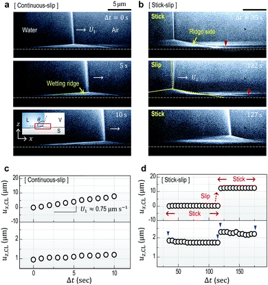
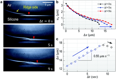
Fig. 1a and b show high-resolution real-time side-view (Fig. 1a, inset) images that display a wetting ridge, the three-phase (solid (S), liquid (L), and vapor (V)) contact line (or the triple point), and the LV-interface. Remarkably, we observe that the wetting ridge migrates with the contact line during drop-spreading; the ridge continuously slips in the early stage (Fig. 1a) and repeatedly shows stick-slip, as demonstrated in Fig. 1b (Movie S1, ESI†) at Δt (elapsed time) = 35–122 s and at Δt = 122–127 s, respectively. Fig. 1c and d show the displacements of the triple point (i.e. the contact line) in the x- (ux,CL) and the z- (uz,CL, i.e. the height of the ridge, H) directions in the continuous – and the stick-slip stages, respectively, measured from the real-time images of Movie S1 (ESI†). In this continuous-slip stage (Fig. 1a), the ridge migrates with a constant velocity (U1 ≈ 0.75 μm s−1; Fig. 1c, top) and a constant macroscopic contact angle (θ) (Fig. 1a) while its height (H ≈ 1 μm) slightly increases (Fig. 1c, bottom). As the height reaches a critical value (H ≈ 1.5 μm at Δt = 16 s in this case, see Movie S1, ESI†), the contact line becomes pinned with a slight increase of θ (Δθ ∼ 3°; compare the LV-interfaces at Δt = 35 s (yellow dashed line) and at Δt = 122 s in Fig. 1b, middle), marking the crossover to the stick-slip stage (Fig. 1b). Interestingly, the ridge height (uz,CL) slightly lowers in sticking (blue arrow heads in Fig. 1d bottom), opposite to the slight heightening during continuous-slip (Fig. 1c, bottom).In addition to ridge lowering, we unexpectedly observe that the base of the ridge side in the dry (air) region broadens, as marked by the red arrow heads (the right endpoints defined by uz = 0 μm) at Δt = 35 s and at Δt = 122 s in Fig. 1b. Fig. 2 shows details of the broadening, taken at a lower part of the ridge side during sticking (Movie S2, ESI†); gradual broadening can be clearly seen from the advancement of the endpoint (red arrow head) in Fig. 2a. Surface profiles (Fig. 2b) extracted from Fig. 2a show the broadening occurs mostly in the base region (blue arrow). The broadening speed ∼0.55 μm s−1 (Fig. 2c) is measured from the real-time images of Movie S2 (ESI†).
3.2 Geometrical change of wetting ridges in sticking
To investigate the geometrical change of wetting ridges observed in sticking, we investigate large-sized ridges (uz,CL > 5 μm) in stick-slip motions, by using thick silicone gel substrates (h ≈ 250 μm).19 Here water is continuously injected into a sessile droplet with a rate of 0.1–0.5 μl min−1 to induce stick-slip motions of the wetting ridge that are recorded in real-time by TXM in a field of view (∼81 μm × ∼81 μm).Fig. 3a shows representative overlapped images of two snapshots of the wetting ridge in sticking, captured at Δt1 = 48.5 s and Δt2 = 188.5 s, respectively, after the ridge sticks at Δt0 = 0 s (see a real-time movie (Movie S3, ESI†)). This clearly demonstrates that the ridge height lowers (red box in Fig. 3a) and the ridge side broadens (see the blue box); the ridge ‘spreads’ during sticking. We will refer this spontaneous behavior of the ridge as ‘the self-spreading of wetting ridges’ or ‘ridge-spreading’. The height ūz,CL (red in Fig. 3b) lowers with increased θ (green in Fig. 3b), measured and averaged for nine sticking events. We note that the stick-to-slip transition occurs mostly during ridge height lowering, as seen by the transition points (star symbols) in Fig. S1 (ESI†), implying a possible contribution of the ridge-spreading behavior to the stick-to-slip transition.
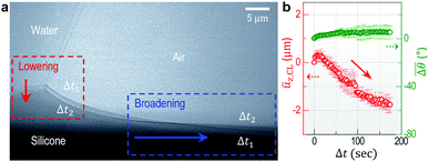 | ||
Fig. 3 Self-spreading of the wetting ridge in sticking. (a) An overlapped image of two snapshots for the spreading ridge taken at Δt1 = 48.5 s and Δt2 = 188.5 s, after sticking at Δt0 = 0 s. The scale bar, 5 μm. (b) The time evolution of the average ridge height, ūz,CL (red circle for the left axis) and the average macroscopic angle,  (green circle for the right axis), measured and averaged for nine events (Fig. S1, ESI†). The ridge height decreases under a little increase of (green circle for the right axis), measured and averaged for nine events (Fig. S1, ESI†). The ridge height decreases under a little increase of  ( ( and and  ). The error bar is standard deviation at each Δt. ). The error bar is standard deviation at each Δt. | ||
Ridge height dynamics can be complex; without a stick-to-slip transition, the ridge eventually stops lowering and the height starts to increase due to creep deformation until the transition takes place (orange arrow in Fig. S1 and Movie S3, ESI†). Note that the heightening rate (∼28.5 nm s−1) is similar to the lowering rate (∼31.5 nm s−1) (black circles in Fig. S1, ESI†). Furthermore, the shape of the ridge cusp is invariant during the entire process (inset images of Fig. S1, ESI†). We can infer from these results that the lowering/heightening is possibly due to viscous flows inside the silicone gel ridge.10,12 In fact, the height lowering in sticking (red in Fig. 3b) is quite noticeable, compared to possible lowering by a little decrease in the vertical tension (γLV![[thin space (1/6-em)]](https://www.rsc.org/images/entities/char_2009.gif) sin
sin![[thin space (1/6-em)]](https://www.rsc.org/images/entities/char_2009.gif) θ) by the small increase in θ (
θ) by the small increase in θ ( in Fig. 3b (green) and θ0 = 105°). This is attributed to the viscoelastic properties of the silicone gel and details will be discussed later.
3.3 Depinning dynamics
To understand the stick-to-slip transition, i.e. the dynamics of the contact line depinning, we track the cusp region in real-time using TXM for a sharp wetting ridge with a large height (uz,CL ≈ 8 μm), prepared on a thin (h ≈ 50 μm) gel substrate12 (Fig. 4a, Δt = 0 s). Depinning is induced by water injection into a sessile droplet. We observe the macroscopic contact angle increases stepwise (Δθ ≈ 3°) by the timely injection of water, as marked by the red arrow heads in Fig. 4c top (Movie S4, ESI†). Notably, the angle significantly increases from θpin (pinning angle) ≈ 108° (Δt = 0 s) up to θdepin (depinning angle) ≈ 123° (Δt = 130 s) (Fig. 4a–c (top)) demonstrating that the large ridge displays a strong pinning enhancement in sticking as quantified by a large hysteresis Δθ (≈16°). In contrast, small ridges induce weaker pinning (small Δθ (≈3°)), as in Fig. 1b.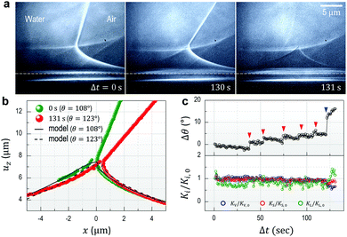 | ||
| Fig. 4 Enhanced contact line pinning by cusp bending. (a) A contact line is strongly pinned by the large ridge with sharp cusp. The wetting ridge remains after depinning (Δt = 131 s). The scale bars, 5 μm. (b) Surface profiles of the wetting ridge extracted from (a). Green and red circles show the initial (Δt = 0 s, θ = 108°) and the final (Δt = 130 s, θ = 123°) state immediately before depinning, respectively. The solid (θ = 108°) and dashed (θ = 123°) lines are calculated from a pinning model adapted from the static wetting model of Bostwick et al.24 by introducing a pinning force proportional to the change in the macroscopic contact angle (Δθ). The agreement between the model and the extracted profiles indicates that additional cusp bending is due to the pinning force. (c) The change in macroscopic angle (Δθ) (upper panel) and the normalized equilibrium constant (Ki/Ki,0, where i = L (blue circles), S (red circles), and V (green circles)), calculated from Neumann's law, as a function of the observing time (Δt). | ||
The mechanism of the pinning enhancement can be deduced from the stepwise bending of the ridge cusp that occurs coincidentally with stepwise increase in θ (Movie S4, ESI† and Fig. 4c, top), which suggests the existence of a horizontal ‘pinning force’ linked to contact-angle hysteresis. We compare our experimental data to a model proposed by Bostwick et al.,24 who computed the deformations of a linear elastic substrate due to a partially-wetting droplet. Here we consider a fully-grown, static sessile ridge, rather than a moving ridge described in a recent linear viscoelastic model.10 In addition to the vertical wetting force Fz(r) = γLV![[thin space (1/6-em)]](https://www.rsc.org/images/entities/char_2009.gif) sin
sin![[thin space (1/6-em)]](https://www.rsc.org/images/entities/char_2009.gif) θ0(δ(r − R) − (2/R)H(R − r)) for the unbalanced component of the liquid/gas surface tension (δ-point force) and the capillary pressure (H-distributed force), we introduce a horizontal pinning force Fr(r) = γLVΔδ(r − R) with Δ = cos
θ0(δ(r − R) − (2/R)H(R − r)) for the unbalanced component of the liquid/gas surface tension (δ-point force) and the capillary pressure (H-distributed force), we introduce a horizontal pinning force Fr(r) = γLVΔδ(r − R) with Δ = cos![[thin space (1/6-em)]](https://www.rsc.org/images/entities/char_2009.gif) θ − cos
θ − cos![[thin space (1/6-em)]](https://www.rsc.org/images/entities/char_2009.gif) θ0 proportional to the deviation in geometric angle θ from its static value θ0 calculated from Young's law (θ0 = 105°, here). This horizontal force is related to contact-angle hysteresis. The calculated ridge profiles in Fig. 4b show that the model (dashed and solid lines are for θ = 108° and 123°, respectively) matches well with the experimental data, which suggests the imbalance of horizontal forces, i.e. break-up of the Young-Dupre equation, may induce additional bending of the cusp with increasing |Δ|. Alternatively, one can view cusp bending as a mechanism for contact-angle hysteresis in soft wetting phenomena. Note that the bent cusp in static wetting (θ0 = 105°) occurs because of asymmetric surface stresses.12
θ0 proportional to the deviation in geometric angle θ from its static value θ0 calculated from Young's law (θ0 = 105°, here). This horizontal force is related to contact-angle hysteresis. The calculated ridge profiles in Fig. 4b show that the model (dashed and solid lines are for θ = 108° and 123°, respectively) matches well with the experimental data, which suggests the imbalance of horizontal forces, i.e. break-up of the Young-Dupre equation, may induce additional bending of the cusp with increasing |Δ|. Alternatively, one can view cusp bending as a mechanism for contact-angle hysteresis in soft wetting phenomena. Note that the bent cusp in static wetting (θ0 = 105°) occurs because of asymmetric surface stresses.12
The microscopic contact angles (θi) are accurately measured at the ridge tip, from which we compute the normalized equilibrium constants Ki/Ki,0, where Ki is an equilibrium constant calculated from Neumann's equation (Ki = sin![[thin space (1/6-em)]](https://www.rsc.org/images/entities/char_2009.gif) θi/γjk for all cyclic permutations of the L, S, and V phases) and Ki,0 is Ki at Δt = 0, as shown in Fig. 4c bottom. Ki/Ki,0 = 1 for i = L, S, and V means that the microscopic contact angles (θi), or the microscopic force balance (i.e. Neumann triangle) at the contact line, is preserved. Fig. 4c top shows that for small increases in θ (Δθ ∼ 3°; red arrow heads), Ki/Ki,0 is around unity by the cusp bending with Δθ (Movie S4, ESI†). This suggests that the microscopic equilibrium is maintained throughout ‘cusp bending’. However, Neumann's triangle suddenly becomes unstable after a large increase in θ (Δθ ∼ 10°; blue arrow head in Fig. 4c, top) at Δt = 121 s resulting in contact-line depinnning (i.e. macroscopic fluid flow or ‘slip’ occurs) at Δt = 131 s (Fig. 4a), which leaves the ridge trace behind.
θi/γjk for all cyclic permutations of the L, S, and V phases) and Ki,0 is Ki at Δt = 0, as shown in Fig. 4c bottom. Ki/Ki,0 = 1 for i = L, S, and V means that the microscopic contact angles (θi), or the microscopic force balance (i.e. Neumann triangle) at the contact line, is preserved. Fig. 4c top shows that for small increases in θ (Δθ ∼ 3°; red arrow heads), Ki/Ki,0 is around unity by the cusp bending with Δθ (Movie S4, ESI†). This suggests that the microscopic equilibrium is maintained throughout ‘cusp bending’. However, Neumann's triangle suddenly becomes unstable after a large increase in θ (Δθ ∼ 10°; blue arrow head in Fig. 4c, top) at Δt = 121 s resulting in contact-line depinnning (i.e. macroscopic fluid flow or ‘slip’ occurs) at Δt = 131 s (Fig. 4a), which leaves the ridge trace behind.
This observation suggests the depinning dynamics underscores the dual-scale nature of the soft wetting phenomena observed in static wetting;12 pinning is maintained as long as the microscopic equilibrium is conserved by the cusp bending, which also mediates the macroscopic non-equilibrium, i.e. the deviation of the geometrical angle θ from θ0. This indicates that the initial pinning originating from viscoelastic energy dissipation by the continuous migration (or continuous formation) of a wetting ridge14 is later enhanced by cusp ‘bending’. In other words, the cusp bending by the horizontal pinning force causes additional energy dissipation, reducing the mobility of the contact line preventing fluid slip (motion).
3.4 Ridge-spreading and depinning dynamics
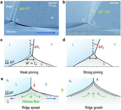
Enhanced contact line pinning by cusp bending highlights the dual-scale nature inherent in soft wetting.12 From this, we infer that microscopic ridge geometry significantly affects macroscopic pinning enhancement. Indeed, as seen in Fig. S1 (ESI†), much weaker pinning is observed in the ridge-spreading stage (as represented by Δθ ≈ 2° in Fig. 5a) than in the ridge-growing stage (Δθ ≈ 16° in Fig. 5b).Now, we address the specific role of ridge-spreading in depinning dynamics, especially accounting for the geometrical effect on the pinning enhancement, schematically illustrated in Fig. 5c and d. From a geometric view, ridge-spreading facilitates depinning (slipping) by making a dull ridge (as in Fig. 5c) that is more unfavorable to cusp bending, i.e. weaker pinning enhancement than a sharp one (as in Fig. 5d). As illustrated in Fig. 5e, when a ridge sliding on a viscoelastic surface suddenly sticks, its momentum diffuses mostly to the sliding direction. Here the momentum flux is proportional to the negative velocity gradient and the viscosity of the viscoelastic gel. This momentum transfer causes ‘broadening’ of the base region (see blue arrow in Fig. 2b, 5a and e), and subsequently, the ridge height decreases due to downward viscous flows (see green arrows in Fig. 5e at t = t1) and mass conservation. At this moment, possible broadening of the left base (left blue arrow) arising from the viscous flows may be suppressed by the Laplace pressure ΔP inside the droplet.28 If no stick-to-slip transition occurs, the ridge-spreading eventually stops and overall growth of the ridge (red arrow in Fig. 5e at t = t2) takes place with upward flows (green arrows) through creep deformation.12 Here, the temporary shrinkage of the ridge base (black arrow of Fig. 2c) is most likely due to the reversal of viscous flows (compare the directions of the green arrows at t = t1 and t2 in Fig. 5e).
4 Discussion
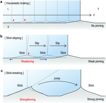
As described above, the ridge migration is directly affected by the ridge development processes and ridge-spreading plays a key role in stick-slip motions. Now, based upon our understanding on the wetting ridge dynamics and the depinning mechanism, we revisit the dynamic wetting behaviors in Fig. 1a, b and 4a.‘Continuous slipping’ (or ‘viscoelastic braking’)14 occurs for sufficiently small ridges (as seen in Fig. 1a and 6a) which require a relatively low energy for migration.14 In this regime, the ridge size H depends on the dwell time of the contact line, i.e. the contact line velocity U, due to viscoelastic properties of the gel,10,12 as demonstrated in Fig. S2a (ESI†) by the opposite tendency of H with respect to changes in U. Here, the continuous ridge migration can be described by the simultaneous processes of (i) the advancement of a contact line along the dry side (uz ≠ 0 μm) of the ridge frozen and (ii) the growth of a new ridge beginning from the side (Fig. S2b, ESI†).23 This also explains the slight increase of ridge height during continuous slipping (Fig. 1c, bottom) for a given U, which will be continued until the ridge reaches its steady state,10 as illustrated in Fig. S3 (ESI†).
For ‘stick-slipping’ and ‘stick-breaking’, the primary differences originate from the wetting ridge dynamics although the transition mechanism based on the failure of Neumann's law at the ridge tip is applicable to both regimes. First, stick-slip occurs for moderately grown ridges, which begin to stick and pin the contact line (Fig. 6b). The sudden sticking of the moving ridge induces ridge-spreading and induces weak pinning or triggers early depinning (Fig. 6b and Fig. S1, ESI†). Here no observed ridge traces after depinning (see Δt = 127 s in Fig. 1b) indicate rapid relaxation of the deformed region.18–20 On the other hand, stick-breaking occurs for the fully grown ridge, which causes strong pinning enhancement via significant cusp bending (as in Fig. 4a). When Neumann's law fails after a large increase in θ, the contact line suddenly ‘jumps’ (Fig. 6c), making a new ridge and leaving a trace of the old ridge (see Δt = 131 s in Fig. 4a), as reported.18,21,22
5 Conclusion
We present direct visualization of wetting ridge dynamics during drop-spreading using TXM with high spatio-temporal resolution and report three key results that highlight the viscoelastic features in ridge formation and the dual-scale nature of the elasto-capillary dynamics. (i) The most striking finding herein is that wetting ridges spread in a stick-slip motion, specifically in sticking which triggers the stick-to-slip transition by enhancing the mobility of the contact line. (ii) We observe that macroscopic contact line pinning is enhanced (or fluid motion inhibited) by cusp bending while preserving the microscopic equilibrium. (iii) Finally, we clarify the mechanics of ‘viscoelastic braking’, ‘stick-slipping’ and ‘stick-breaking’, accounting for the ridge development and the depinning dynamics underlying each behavior.We believe our results on soft wetting dynamics can give substantial inspiration to elucidate dynamic wetting on soft solids, particularly those involving contact line pinning, such as evaporation,28 contact angle hysteresis,29,30 drop impact,30 and condensation.31 In particular, more systematic investigation about the ridge-spreading behavior originating from properties of the soft surface will provide further understanding on surface rheology, in particular, related with many complex biological issues caused by cell–substrate interactions.
Conflicts of interest
There are no conflicts to declare.Acknowledgements
We thank Eric R. Dufresne and Robert W. Style for helpful comments on this work. We also thank Guy K. German and Hojae Gwak for preparing the soft substrates. This work was supported by the Ministry of Trade, Industry and Energy (MOTIE) and the Korea Institute for Advancement of Technology (KIAT) through the International Cooperative R&D Program and also by Brain Korea 21 PLUS Project for the Center for Creative Industrial Materials. Use of the Advanced Photon Source, an Office of Science User Facility operated for the U.S. Department of Energy (DOE) Office of Science by the Argonne National Laboratory, was supported by the U.S. DOE under Contract No. DE-AC02-06CH11357.References
- I. Levental, P. C. Georges and P. A. Janmey, Soft Matter, 2007, 3, 299–306 RSC.
- D. E. Discher, P. Janmey and Y. L. Wang, Science, 2005, 310, 1139–1143 CrossRef CAS PubMed.
- M. J. Paszek, N. Zahir, K. R. Johnson, J. N. Lakins, G. I. Rozenberg, A. Gefen, C. A. Reinhart-King, S. S. Margulies, M. Dembo, D. Boettiger, D. A. Hammer and V. M. Weaver, Cancer Cell, 2005, 8, 241–254 CrossRef CAS PubMed.
- A. J. Engler, M. A. Griffin, S. Sen, C. G. Bönnemann, H. L. Sweeney and D. E. Discher, J. Cell Biol., 2004, 166, 877–887 CrossRef CAS PubMed.
- A. Subramanian and H. Y. Lin, J. Biomed. Mater. Res., Part A, 2005, 75, 742–753 CrossRef PubMed.
- S. Douezan, K. Guevorkiana, R. Naouara, S. Dufourb, D. Cuveliera and F. Brochard-Wyarta, Proc. Natl. Acad. Sci. U. S. A., 2011, 108, 7315–7321 CrossRef CAS PubMed.
- S. Douezan, J. Dumond and F. Brochard-Wyart, Soft Matter, 2012, 8, 4578–4583 RSC.
- A. F. Mertz, S. Banerjee, Y. Che, G. K. German, Y. Xu, C. Hyland, M. C. Marchetti, V. Horsley and E. R. Dufresne, Phys. Rev. Lett., 2012, 108, 198101 CrossRef PubMed.
- R. W. Style, Y. Che, S. J. Park, B. M. Weon, J. H. Je, C. Hylande, G. K. Germanb, M. P. Power, L. A. Wilen, J. S. Wettlaufer and E. R. Dufresne, Proc. Natl. Acad. Sci. U. S. A., 2013, 379, 432–434 Search PubMed.
- S. Karpitschka, S. Das, M. van Gorcum, H. Perrin, B. Andreotti and J. H. Snoeijer, Nat. Commun., 2015, 6, 7891 CrossRef CAS PubMed.
- D. Long, A. Ajdari and L. Leibler, Langmuir, 1996, 12, 5221–5230 CrossRef CAS.
- S. J. Park, B. M. Weon, J. S. Lee, J. Lee, J. Kim and J. H. Je, Nat. Commun., 2014, 5, 4369 CAS.
- E. R. Jerison, Y. Xu, L. A. Wilen and E. R. Dufresne, Phys. Rev. Lett., 2011, 106, 186103 CrossRef PubMed.
- A. Carré, J.-C. Gastel and M. E. R. Shanahan, Nature, 1996, 379, 432–434 CrossRef.
- R. Pericet-Camara, G. K. Auernhammer, K. Koynov, S. Lorenzoni, R. Raiteric and E. Bonaccurso, Soft Matter, 2009, 5, 3611–3617 RSC.
- L. Chen, G. K. Auernhammer and E. Bonaccurso, Soft Matter, 2011, 7, 9084 RSC.
- L. Chen, E. Bonaccurso and M. E. Shanahan, Langmuir, 2013, 29, 1893–1898 CrossRef CAS PubMed.
- G. Pu and S. J. Severtson, J. Phys. Chem. C, 2011, 115, 18729–18735 CAS.
- T. Kajiya, A. Daerr, T. Narita, L. Royon, F. Lequeux and L. Limat, Soft Matter, 2013, 9, 454–461 RSC.
- T. Kajiya, P. Brunet, L. Royon, A. Daerr, M. Receveur and L. Limat, Soft Matter, 2014, 10, 8888–8895 RSC.
- G. Pu, J. Guo, L. E. Gwin and S. J. Severtson, Langmuir, 2007, 23, 12142–12146 CrossRef CAS PubMed.
- G. Pu and S. J. Severtson, Langmuir, 2008, 24, 4685–4692 CrossRef CAS PubMed.
- L. Limat, Eur. Phys. J. E: Soft Matter Biol. Phys., 2012, 35, 134 CrossRef CAS PubMed.
- J. B. Bostwick, M. Shearer and K. E. Daniels, Soft Matter, 2014, 10, 7361–7369 RSC.
- Y.-T. Chen, et al. , Opt. Lett., 2011, 36, 1269–1271 CrossRef PubMed.
- V. de Andrade, A. Deriy, M. J. Wojcik, D. Gürsoy, D. Shu, K. Fezzaa and F. De Carlo, SPIE Newsroom., 2016, DOI: 10.1117/2.1201604.006461.
- R. W. Style, R. Boltyanskiy, G. K. German, C. Hyland, C. W. MacMinn, A. F. Mertz, L. A. Wilen, Y. Xuc and E. R. Dufresne, Soft Matter, 2014, 10, 4047–4055 RSC.
- G. Pu and S. J. Severtson, Langmuir, 2012, 28, 10007–10014 CrossRef CAS PubMed.
- C. W. Extrand and Y. Kumagai, J. Colloid Interface Sci., 1996, 184, 191–200 CrossRef CAS PubMed.
- R. Rioboo, M. Voué, H. Adão, J. Conti, A. Vaillant, D. Seveno and J. de Coninck, Langmuir, 2010, 26, 4873–4879 CrossRef CAS PubMed.
- M. Sokuler, G. K. Auernhammer, M. Roth, C. Liu, E. Bonacurrso and H.-J. Butt, Langmuir, 2010, 26, 1544–1547 CrossRef CAS PubMed.
- R. W. Style, R. Boltyanskiy, G. K. German, C. Hyland, C. W. MacMinn, A. F. Mertz, L. A. Wilen, T. Xuc and E. R. Dufresne, Phys. Rev. Lett., 2013, 110, 066103 CrossRef PubMed.
- L. A. Lubbers, J. H. Weijs, L. Botto, S. Das, B. Andreotti and J. H. Snoeijer, J. Fluid Mech., 2014, 747, R1 CrossRef CAS.
- L. R. White, J. Colloid Interface Sci., 2003, 258, 82–96 CrossRef CAS.
Footnotes |
| † Electronic supplementary information (ESI) available. See DOI: 10.1039/c7sm01408b |
| ‡ Present address: Chemical Engineering, Stanford University, Stanford, CA 94305, USA. |
| This journal is © The Royal Society of Chemistry 2017 |

