Multi-shell tin phosphide nanospheres as high performance anode material for a sodium ion battery†
Sheng
Huang‡
a,
Chao
Meng‡
a,
Min
Xiao
a,
Shan
Ren
a,
Shuanjin
Wang
a,
Dongmei
Han
*b,
Yuning
Li
 c and
Yuezhong
Meng
 *a
*a
aThe Key Laboratory of Low-carbon Chemistry & Energy Conservation of Guangdong Province, State Key Laboratory of Optoelectronic Materials and Technologies, School of Materials Science and Engineering, Sun Yat-Sen University, Guangzhou 510275, PR China. E-mail: mengyzh@mail.sysu.edu.cn
bSino-French Institute of Nuclear Engineering and Technology, Sun Yat-Sen University, Zhuhai 519082, PR China. E-mail: handongm@mail.sysu.edu.cn
cDepartment of Chemical Engineering, Waterloo Institute for Nanotechnology (WIN), 200 University Ave W, Waterloo, Ontario N2L 3G1, Canada
First published on 1st September 2017
Abstract
Tin phosphide (Sn4P3) combined with the good conductivity of tin (Sn) and high capacity of phosphorus has been reported to be a potential anode material for the sodium ion battery (SIB). However, the preparation of Sn4P3 is limited to ball-milling and compositing with carbon materials. The novel and detailed structure of Sn4P3 itself has so far not been revealed. In this research, the multi-shell Sn4P3 nano-structure was obtained, for the first time, using a simple and general low temperature solvothermal method. The multi-shell structure with a larger specific surface area and interlayer space endows this new anode material with a short cut pathway for sodium ion diffusion and a buffer space for volume expansion during sodiation, thus avoiding electrode pulverization and improving the cycling performance of the SIB. The as-prepared multi-shell Sn4P3 delivers an excellent specific capacity of 770 mAh g−1 with capacity retention of 96% after 50 cycles at the current density of 50 mA g−1, demonstrating the superiority of structure optimization in SIB anode preparation.
1. Introduction
The discovery of high performance rechargeable batteries initiated the development of portable electronics and electric vehicles until nowadays there is a bottleneck in their further development because of the battery capacity.1 Meanwhile, sodium ion batteries (SIB) with abundance of reserve capacity and cost advantage are becoming the best alternative to lithium ion batteries (LIBs).2 These factors stimulated the search for sodium storage materials with a high capacity and cycle stability.3 Various intercalation-based cathode materials for SIB [e.g., sodium cobalt oxide (NaCoO2) sodium manganese oxide (NaMnO2), sodium iron phosphate (NaFePO4)] have been developed by replacing lithium with sodium (Na).4–7 But the commercial graphite anode of LIBs failed to repeat its success in SIB because its size mismatch with the Na ion.8,9 So attention was drawn to the alloy-based anode promising a high Na capacity. Sodium alloyed elements in group IV such as germanium (Na15Ge4, 369 mAh g−1),10 tin (Na15Sn4, 847 mAh g−1)11–13 or lead (Na15Pb4, 485 mAh g−1),14 and those in group V such as phosphorus (Na3P, 2596 mAh g−1)15–19 and antimony (Na3Sb, 660 mAh g−1)20,21 have been proved to be high capacity anode candidates. In the charge–discharge process, however, the solid electrolyte interface (SEI) would be broken by the 3–5 times volume expansion of these anode particles which then re-grow at the solid–liquid interfaces, leading to inferior cycle stability with the Na ion and electrolyte solution depletion.22,23It has been reported that Sn shows the best conductivity and P has the highest capacity among the Na-alloy based anode materials.24 These advantages are integrated in tin phosphide (Sn4P3) with a synergetic Na-storage mechanism.25 However, very little work has been done to prepare the Sn4P3 compound, except for a mechanical ball milling methodology,25–28 whereby the diameters of the particles obtained reach several micrometers which result in cracking during the battery reaction. Recently, some chemical methods were developed to improve the anode performance of Sn4P3. Uniform yolk–shell Sn4P3@C nanospheres (NSs) were synthesized using an annealing phosphidation route29 and Sn4P3/graphene hybrids were synthesized using in situ solvothermal phosphidation.24 This research for improving the anode performance concentrated on recombination with the conductive carbon materials. Nevertheless, there is no report on synthesis innovation and structure optimization of Sn4P3 itself.
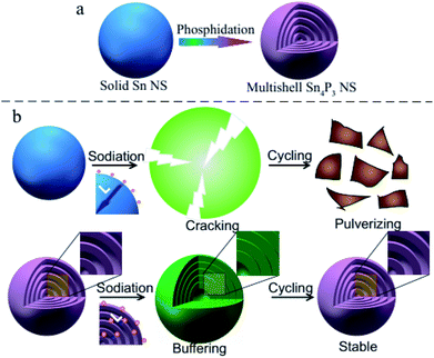
In this research, the multi-shell Sn4P3 NSs are synthesized for the first time using a white phosphorus solution-based solvothermal phosphidation route using commercially available Sn NSs [Scheme 1(a)]. The simple solvothermal synthetic strategy for the fabrication of Sn4P3 NSs exhibits a unique multi-shell structure. This architecture combines a large specific area and interlayer void space in Sn4P3 used as the anode of SIB, providing a shorter pathway of Na ion diffusion and buffer space for volume expansion in the charge–discharge process to avoid cracking and pulverization [Scheme 1(b)]. Furthermore, the multi-shell Sn4P3 electrode shows an excellent electrochemical performance in terms of reversibility, rate capability and cycle stability, which is superior to the other solid/hollow structures of Sn or Sn4P3. Finally, this solvothermal strategy is simple and scalable, and will be a general method for fabricating a multi-shell structure that will be useful in many fields.
In principle, the approaches to improve the Na transport kinetics in electrode materials mainly involve reducing the diffusion length (L) and enhancing the Na diffusion coefficient (D).30,31 These improvements can be fulfilled by the unique and novel structure of the multi-shell Sn4P3 NSs: before the charge–discharge process, Na ions are able to penetrate into the inner interlayer space rather than outside the particle in case of solid nanospheres, therefore the diffusion length L [Scheme 1(b)] during the electrochemical reaction would be remarkably reduced. Also, the Na diffusion coefficient D in the SEI is believed to be larger than that in the solid active mass, so the sodium diffusion coefficient D can be enhanced by the multi-shell Sn4P3 NSs with more interfaces. Furthermore, the interlayer void space can buffer the volume expansion thus avoiding particle cracking and maintaining the integrity of the ion pathway during the battery cycle [Scheme 1(b)].32 Subsequent step by step characterization and testing will verify these principles.
2. Experimental section
2.1 Preparation of Sn4P3 NSs
White phosphorus (use caution, very dangerous) in a solution of benzene (Tianjin Baishi Chemical Industry Co. Ltd.) was first prepared by dissolving 2 g white phosphorus in 70 mL of benzene assisted with ultrasonic mixing. Tin nanoparticles (Aladdin) were mixed with 15 mL of the solution of white phosphorus in benzene in a 20 mL Teflon-lined stainless-steel autoclave and then placed in an oven for the reaction to occur. Typically, the reaction conditions for producing multi-shell Sn4P3 NSs is 200 °C for 40 h. The gray/black product was separated using centrifugation and then washed with ethanol to remove the impurities. Finally, the Sn4P3 NSs were dried in a vacuum oven at 50 °C for 24 h.2.2 Characterization
The morphology of the products was observed with transmission electron microscopy (TEM, Jeol JEM-2010HR). The structures of the products were characterized using X-ray powder diffractometry (XRD, PANalytical Empyrean). Nitrogen (N2) adsorption–desorption isotherms and specific surface area were characterized using an accelerated surface area and porosity analyzer (Micromeritics, ASAP 2460).2.3 Electrochemical measurements
The working electrode slurry was prepared by mixing 56 wt% of active materials, 34 wt% of acetylene carbon black (Super P), 10 wt% of carboxymethylcellulose sodium (NaCMC binder; Aladdin), and an adequate amount of deionized water and this was followed by ball-milling at 160 rpm for 24 h. The performance of the SIBs was tested using standard 2032 type coin cells with carbon coated aluminium (Al) foil as the current collectors, Na foil as the counter electrode and reference electrodes, glass fiber (GF/F; Whatman) as a separator, and 1.0 M sodium perchlorate in propylene carbonate plus 5 wt% fluoroethylene carbonate (DoDoChem) as the electrolyte. The weight of the electrode used in this study was about 0.98 mg cm−2 and the diameter of the electrode was 1.4 cm. The cut-off voltage window was 0.01–2.00 V. The galvanostatically cycled test was carried out on a Neware instrument at room temperature. Cyclic voltammetry (CV) and electrochemical impedance spectroscopy (EIS) were carried out using a frequency response analyzer (Solartron 1255B) coupled with an electrochemical interface (Solartron 1287). The CV was measured in a potential window of 0.01–2.00 V at a scan rate of 0.1 mV s−1. EIS measurements were performed in the frequency between 105 Hz and 0.1 Hz and the amplitude was 5 mV.3. Results and discussion
3.1 Material preparation and characterization
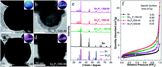
The multishell Sn4P3 NSs were prepared using a direct solvothermal treatment of Sn NSs in a solution of white phosphorus in benzene. TEM images show that the solid Sn NSs are roughly discrete and uniform with an average size of around 120 nm (Fig. 1a). These Sn NSs were transformed into double-layer Sn4P3 using a solvothermal reaction at 160 °C for 40 h in a solution of white phosphorus in benzene. The powder X-ray diffraction (XRD) analysis (Fig. 1e) of the solvothermal product prepared at 160 °C for 40 h (Sn4+xP3/160-40 for short) shows that part of the diffraction peaks (Sn: 2θ = 30.6°, 32.0°, 43.8°, 44.9°, and so on) can be indexed to the tetragonal Sn phase, indicating that the phosphidation of the Sn is incomplete. Complete phosphidation of Sn NSs was obtained using a solvothermal treatment at 200 °C for 40 h, and this was indicated because there were no Sn diffraction peaks remaining in the XRD pattern of Sn4P3/200-40 (Sn4P3: 2θ = 28.8°, 30.3°, 31.5°, 44.5°). Meanwhile, multi-shell Sn4P3 NSs were obtained under conditions of 200 °C-40 h, and 4–5 layer phosphide particles are observed in the TEM image (Fig. 1c). Upon prolonged heating, a more remarkable nanoscale Kirkendall effect33,34 was observed, and hollow Sn4P3 NSs were produced after reaction at 200 °C for 80 h. However, these particles tend to aggregate at the same time. The N2 adsorption–desorption isotherms and the corresponding specific surface area of the Sn NSs and the synthesized Sn4P3 NSs obtained using the Barrett–Joyner–Halenda method are shown in Fig. 1f. The specific surface areas of the solid Sn, double-shell Sn4+xP3/160-40 and multi-shell Sn4P3/200-40 were 3.43, 6.90 and 8.79 m2 g−1, respectively, and which increase with the reaction temperature. Nevertheless, for Sn4P3/200-80, the particle aggregation and complete hollowing lead to the reduction of specific surface area and this is consistent with the TEM images.3.2 Cyclic voltammetry
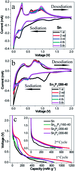
To understand and compare the electrochemical reactions of the Sn NSs and the synthesized multi-shell Sn4P3/200-40 NSs, CV of the Sn/C (Fig. 2a) and the Sn4P3/200-40/C (Fig. 2b) SIB were performed at a scan rate of 0.1 mV s−1 in a voltage range of 0.01–2.00 V versus Na+/Na. In particular, the first cycle curve contains not only reduction of Sn or Sn4P3, but also the irreversible Na storage by Super P and electrolyte decomposition to form a SEI film. So the first cycle can be considered as the pre-cycle that is not suitable for characteristic reaction analysis. As shown in the curves of the 2nd–5th cycles in the Fig. 2a, four oxidative peaks at around 0.29 V, 0.59 V, 0.73 V and 0.92 V were assigned to the desodiation of Na15Sn4, Na9Sn4, NaSn, and NaSn5, respectively. These phenomena agree well with the previous reports on the Sn SIB.13 However, these particles did not overlay well with each other because the Sn NSs had no space to accommodate the volume expansion, and thus cracked and became pulverized during the cycle process. For the multi-shell Sn4P3/200-40 NSs, the characteristic oxidative peaks of Sn4P3 SIB were assigned to 0.36 V and 0.73 V, respectively. The peak at 0.36 V corresponds to the desodiation of the Na15Sn4 alloys, and the peak at 0.73 V could be attributed to the Na3P dealloying reaction together with further desodiation of NaxSny. Contrary to Sn NSs, the curves of the 2nd–5th cycles for multi-shell Sn4P3/200-40 NSs SIB overlay well with each other, because the volume expansion during the cycle can be buffered by the interlayer space of the special multi-shell structure, in which the inner stress can be released to avoid cracking and pulverization. Another advantage of using the multi-shell structure as anode material is because it functions as a short cut for the diffusion of the sodium ions during the alloying–dealloying reaction, because the interlayer space provides an efficient diffusion channel and storage space for the ions. As shown in Fig. 2c, the multi-shell Sn4P3/200-40 NSs gives the highest discharging capacity in the 1st and 2nd cycle, because not only is the theoretical capacity of Sn4P3 higher than pure Sn, but also, more importantly, the multi-shell structure with its larger specific area makes more active materials available for effective sodiation.3.3 Electrochemical impedance spectrum
The charge transfer kinetics of Sn or Sn4P3 SIBs electrodes was further investigated using EIS. Fig. 3 shows the Nyquist profiles of the AC impedance measured at an open circuit voltage state of fresh cells and cells at the fully charged state after several cycles for the Sn/C or Sn4P3/C electrodes. As shown in Fig. 3a, the Sn4P3 exhibits a larger contact resistance than Sn because of the conductivity reduction from the phosphidation. Furthermore, the aggregated and completely hollow Sn4P3/200-80 NSs with the most nonconductive inner space and the worst contact with conductive additives shows the largest impedance. Fig. 3b shows the Nyquist plots of the Sn/C and Sn4P3/200-40/C electrode before the cycles and after the 10th/50th cycles at the full charged state. With increasing cycles, the electrode materials experience full surface activation and volume expansion, leading to significant impedance reduction until they remain roughly unchanged (Sn4P3/200-40) or after rinsing again (Sn). The multi-shell Sn4P3/200-40 NSs with adequate buffer space for volume expansion can maintain good structure integrity, so the impedance after 50 cycles is more or less the same as that after 10 cycles, which is the same as for the Sn NSs. However, the extensive cycling may result in electrode cracking and increase of contact impedance as shown by 10th and 50th curve of Sn.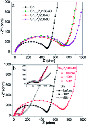 | ||
| Fig. 3 (a) Nyquist plots of the different Sn or Sn4P3 batteries before cycling and (b) Nyquist plots of the different Sn or Sn4P3 batteries after different cycles at the fully charged state. | ||
3.4 Battery performance
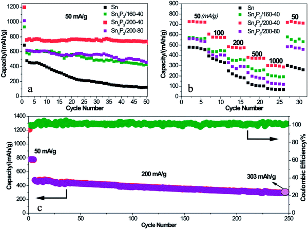
To further prove the structural superiority of the multi-shell Sn4P3 NSs in battery performance, the SIB of Sn or Sn4P3 with different structures were cycled at a current of 50 mA g−1 for 50 cycles in the voltage range of 0.01–2.00 V. As shown in Fig. 4a, the multi-shell Sn4P3/200-40/C electrode delivers a discharge capacity of 1200 mAh g−1 for the 1st cycle and the reversible capacity of 770 mAh g−1. The initial irreversible capacity could be ascribed to the irreversible Na storage of Super P and the formation of SEI films. Notably, the multi-shell Sn4P3/200-40 NSs with the largest specific area among all materials lead to more SEI film formation than any other electrode materials. This is why the multi-shell Sn4P3/200-40 NSs have the highest 1st cycle capacity, reversible capacity and the largest irreversible capacity at the same time. Furthermore, the multi-shell Sn4P3/200-40 NSs maintain 96% capacity (738 mAh g−1) of the 2nd cycle after 50 cycles, whereas the retention rates of Sn, Sn4+xP3/160-40 and Sn4P3/200-80 are 25%, 73%, and 74%, respectively.As shown in Fig. 4b, the Sn and Sn4P3 electrodes are each cycled for five cycles at an increasing current density from 50 mA g−1 to 1000 mA g−1 to prove the rate capability dominance of the multi-shell Sn4P3. The multi-shell Sn4P3/200-40 electrodes deliver the discharge capacities of 727, 575, 477, 372 and 300 mAh g−1 at the currents of 50, 100, 200, 500 and 1000 mA g−1, respectively. It can be seen that the capacity can be recovered to 727 mAh g−1 when the current was returned to 50 mA g−1. The rate capabilities of Sn, Sn4+xP3/160-40 and Sn4P3/200-80 are also presented in Fig. 4b. It is apparent that the Sn4P3/200-40 electrode is much superior to the other electrodes at each current density, indicating the admirable stability and elasticity of the multi-shell structure. To further evaluate the capacity output and cycle stability, a higher current density of 200 mA g−1 was applied to the Sn4P3/200-40 electrode within a range of 0.01–2.00 V. As shown in Fig. 4c, after 500 cycles, a high discharge capacity of 303 mAh g−1 can be still delivered with more than 63% retention.
4. Conclusions
In summary, a simple solvothermal synthetic strategy has been successfully developed for the fabrication of Sn4P3 NSs with a unique multi-shell structure. This architecture combines the large specific area and interlayer void space of Sn4P3 as the SIB anode, providing a short cut pathway of sodium ion diffusion and buffer space for volume expansion in the charge–discharge process to avoid cracking and pulverization. The multi-shell Sn4P3 electrode shows an excellent electrochemical performance in terms of reversibility, rate capability and cycle stability, which is superior to other solid/hollow structures of Sn or Sn4P3. Furthermore, this solvothermal strategy is simple and scalable and may be a general methodology for fabricating multi-shell structures for various applications.Conflicts of interest
There are no conflicts of interest to declare.Acknowledgements
The Authors would like to thank the Link Project of the National Natural Science Foundation of China and Guangdong Province (Grant No. U1301244); National Natural Science Foundation of China (Grant No. 51573215, 21506260); Guangdong Province Science & Technology Foundation (2011B050300008); Guangdong Natural Science Foundation (Grant No. 2014A030313159, 2016A030313354); Guangdong Province Sci & Tech Bureau (Key Strategic Project Grant No. 2016B010114004); and Guangzhou Scientific and Technological Planning Project (2014J4500002, 201607010042) for financial support of this work.Notes and references
- R. Van Noorden, Nature, 2014, 507, 26–28 CrossRef CAS PubMed.
- M. D. Slater, D. Kim, E. Lee and C. S. Johnson, Adv. Funct. Mater., 2013, 23, 947–958 CrossRef CAS.
- H. Kim, Z. Ding, M. H. Lee, K. Lim, G. Yoon and K. Kang, Adv. Energy Mater., 2016, 6, 1600943 CrossRef.
- R. Berthelot, D. Carlier and C. Delmas, Nat. Mater., 2011, 10, 74–80 CrossRef CAS PubMed.
- N. Yabuuchi, M. Kajiyama, J. Iwatate, H. Nishikawa, S. Hitomi, R. Okuyama, R. Usui, Y. Yamada and S. Komaba, Nat. Mater., 2012, 11, 512–517 CrossRef CAS PubMed.
- J. Kim, D. H. Seo, H. Kim, I. Park, J. K. Yoo, S. K. Jung, Y. U. Park, W. A. Goddard and K. Kang, Energy Environ. Sci., 2015, 8, 540–545 CAS.
- Y. E. Zhu, X. G. Qi, X. Q. Chen, X. L. Zhou, X. Zhang, J. P. Wei, Y. S. Hu and Z. Zhou, J. Mater. Chem. A, 2016, 4, 11103–11109 CAS.
- B. Jache and P. Adelhelm, Angew. Chem., Int. Ed., 2014, 53, 10169–10173 CrossRef CAS PubMed.
- Y. Wen, K. He, Y. J. Zhu, F. D. Han, Y. H. Xu, I. Matsuda, Y. Ishii, J. Cumings and C. S. Wang, Nat. Commun., 2014, 5, 4033 CAS.
- X. T. Lu, E. R. Adkins, Y. He, L. Zhong, L. L. Luo, S. X. Mao, C. M. Wang and B. A. Korgel, Chem. Mater., 2016, 28, 1236–1242 CrossRef CAS.
- Y. C. Liu, N. Zhang, L. F. Jiao and J. Chen, Adv. Mater., 2015, 27, 6702–6707 CrossRef CAS PubMed.
- Z. Li, J. Ding and D. Mitlin, Acc. Chem. Res., 2015, 48, 1657–1665 CrossRef CAS PubMed.
- Y. H. Xu, Y. J. Zhu, Y. H. Liu and C. S. Wang, Adv. Energy Mater., 2013, 3, 128–133 CrossRef CAS.
- A. Darwiche, R. Dugas, B. Fraisse and L. Monconduit, J. Power Sources, 2016, 304, 1–8 CrossRef CAS.
- Y. Kim, Y. Park, A. Choi, N. S. Choi, J. Kim, J. Lee, J. H. Ryu, S. M. Oh and K. T. Lee, Adv. Mater., 2013, 25, 3045–3049 CrossRef CAS PubMed.
- J. F. Qian, X. Y. Wu, Y. L. Cao, X. P. Ai and H. X. Yang, Angew. Chem., Int. Ed., 2013, 52, 4633–4636 CrossRef CAS PubMed.
- J. X. Song, Z. X. Yu, M. L. Gordin, S. Hu, R. Yi, D. H. Tang, T. Walter, M. Regula, D. Choi, X. L. Li, A. Maniyannan and D. H. Wang, Nano Lett., 2014, 6329–6335 CrossRef CAS PubMed.
- J. Sun, H. W. Lee, M. Pasta, H. T. Yuan, G. Y. Zheng, Y. M. Sun, Y. Z. Li and Y. Cui, Nat. Nanotechnol., 2015, 10, 980 CrossRef CAS PubMed.
- H. Gao, T. F. Zhou, Y. Zheng, Y. Q. Liu, J. Chen, H. K. Liu and Z. P. Guo, Adv. Energy Mater., 2016, 6, 1601037 CrossRef.
- L. Y. Hu, X. S. Zhu, Y. C. Du, Y. F. Li, X. S. Zhou and J. C. Bao, Chem. Mater., 2015, 27, 8138–8145 CrossRef CAS.
- L. B. Wang, C. C. Wang, N. Zhang, F. J. Li, F. Y. Cheng and J. Chen, ACS Energy Lett., 2017, 2, 256–262 CrossRef CAS.
- R. Mogensen, D. Brandell and R. Younesi, ACS Energy Lett., 2016, 1, 1173–1178 CrossRef CAS.
- J. W. Wang, X. H. Liu, S. X. Mao and J. Y. Huang, Nano Lett., 2012, 12, 5897–5902 CrossRef CAS PubMed.
- Q. Li, Z. Q. Li, Z. W. Zhang, C. X. Li, J. Y. Ma, C. X. Wang, X. L. Ge, S. H. Dong and L. W. Yin, Adv. Energy Mater., 2016, 6, 1600376 CrossRef.
- J. F. Qian, Y. Xiong, Y. L. Cao, X. P. Ai and H. X. Yang, Nano Lett., 2014, 14, 1865–1869 CrossRef CAS PubMed.
- Y. Kim, A. Choi, S. Woo, D. Mok, N. S. Choi, Y. S. Jung, J. H. Ryu, S. M. Oh and K. T. Lee, Adv. Mater., 2014, 26, 4139–4144 CrossRef CAS PubMed.
- W. J. Li, S. L. Chou, J. Z. Wang, J. H. Kim, H. K. Liu and S. X. Dou, Adv. Mater., 2014, 26, 4037–4042 CrossRef CAS PubMed.
- X. L. Fan, J. F. Mao, Y. J. Zhu, C. Luo, L. M. Suo, T. Gao, F. D. Han, S. C. Liou and C. S. Wang, Adv. Energy Mater., 2015, 5, 1500174 CrossRef.
- J. Liu, P. Kopold, C. Wu, P. A. van Aken, J. Maier and Y. Yu, Energy Environ. Sci., 2015, 8, 3531–3538 CAS.
- C. Wu, P. Kopold, P. A. van Aken, J. Maier and Y. Yu, Adv. Mater., 2017, 29, 1604015 CrossRef PubMed.
- H. G. Zhang, X. D. Yu and P. V. Braun, Nat. Nanotechnol., 2011, 6, 277–281 CrossRef CAS PubMed.
- N. Liu, Z. D. Lu, J. Zhao, M. T. McDowell, H. W. Lee, W. T. Zhao and Y. Cui, Nat. Nanotechnol., 2014, 9, 187–192 CrossRef CAS PubMed.
- R. K. Chiang and R. T. Chiang, Inorg. Chem., 2007, 46, 369–371 CrossRef CAS PubMed.
- Y. D. Yin, R. M. Rioux, C. K. Erdonmez, S. Hughes, G. A. Somorjai and A. P. Alivisatos, Science, 2004, 304, 711–714 CrossRef CAS PubMed.
Footnotes |
| † Electronic supplementary information (ESI) available. See DOI: 10.1039/c7se00355b |
| ‡ SH and CM have contributed equally to this work. |
| This journal is © The Royal Society of Chemistry 2017 |

