Facile synthesis of ultrafine Ru nanocrystal supported N-doped graphene as an exceptional hydrogen evolution electrocatalyst in both alkaline and acidic media†
Barun Kumar
Barman
 ,
Debanjan
Das
 and
Karuna Kar
Nanda
 *
*
Materials Research Centre, Indian Institute of Science, Bangalore-560012, India. E-mail: nanda@mrc.iisc.ernet.in; Fax: +91 80 2360 7316; Tel: +91 80 2293 2996
First published on 28th April 2017
Abstract
Since hydrogen is a clean and renewable energy source, the design of efficient and new catalysts for hydrogen evolution reaction (HER) has attracted significant attention. Ultrafine (∼2 nm) monodispersed Ru nanocrystals on N-doped graphene (Ru@NG) show Pt-like catalytic activity towards HER in both alkaline and acidic media with zero onset potential and better current density as compared to Pt/C. The HER performance strongly depends on the nanosize effect of Ru nanocrystals and their dispersion on NG. Transfer of electrons from Ru to carbon results in an electron-deficient metal centre and greatly enhances the HER activity. This new 4-d transition metal electrocatalyst has the potential to serve as an alternative to the Pt benchmark catalyst, which is more costly than Ru.
There is an urgency to find clean and renewable energy alternatives1–4 to combat the problems associated with fossil fuel-based energy sources in the present world. In this regard, hydrogen, an abundant and renewable energy source, is a promising solution.5 Electrochemical hydrogen evolution reaction (HER) via water splitting is an attractive route for the generation of large scale high-purity hydrogen in a sustainable manner.3 However, a catalyst is required for HER to efficiently proceed with a low overpotential.4–10 Pt-based catalysts currently form the state-of-the-art HER electrocatalysts due to their low reduction overpotential and fast reduction kinetics.11,12 However, their acute scarcity and high-cost impede their large scale application. In this regard, nanostructures of transition metal chacogenides, carbides, phosphides, oxides, and their hybrids have been explored.13–30 Despite their HER catalytic performance, these catalysts are significantly inferior to the Pt-based catalysts in terms of high overpotentials and low current density. Furthermore, the catalysts are active either in an acidic or in an alkaline medium. The realization of a Pt-free catalyst in both acid and alkaline media is of great importance with industrial relevance; however, only a few catalysts are active in both media.
Ru-based nanocrystals (NCs) are demonstrated to be of great importance in various heterogeneous catalytic reactions.31–39 However, catalysts should be in the size range of 2–6 nm, and the surface area needs to be large for better catalytic activity; moreover, it is a challenge to optimize the size and morphology of the catalysts. Furthermore, the support for the catalysts and their interaction play a significant role in the stability as well as on the performance of the catalyst. In this regard, N-doped graphene (NG) has proven to be highly beneficial as a support for the catalysts. Although there are few reports on the chemical synthesis of Ru NCs, synthesis of ultra-small and uniform sized Ru NCs on an NG support still remains a challenge.
Herein, we demonstrated a physical technique for the in situ synthesis of self-assembled ultrafine Ru nanocrystals (∼2 nm) on N-doped graphene (Ru@NG) for the first time and explored their HER activity in both acid and alkaline media. Ru@NG shows exceptional HER catalytic activity in both acid and alkaline media, with zero onset potential like commercial precious Pt/C, and better current density. Thus, Ru@NG holds great promise as a new material for the generation of hydrogen from water.
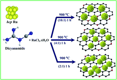
The synthesis of NG-supported ultrafine Ru NCs (Ru@NG) is based on a one-pot strategy. The synthesis was accomplished through a very simple and convenient experimental setup (ESI-1†) that involved the pyrolysis of RuCl3·xH2O and dicyanamide (DCA) in a sealed quartz tube without any external gas flow. During the pyrolysis, Ru3+ ions were reduced to ultrafine Ru NCs, whereas the DCA decomposed and formed the NG support (Scheme 1). For simplicity, the as-prepared samples are named Ru@NG-x, which indicates the mass ratio (x) of DCA and the RuCl3·xH2O compound in the precursor (Table S-1†).
Transmission electron microscopy (TEM) and high resolution TEM (HRTEM) images of Ru@NG-10, as shown in Fig. 1(A and B), reveal that Ru NCs have sizes 4–5 nm (ESI-2†) and are decorated on NG. Fig. 1(C and D) show the TEM and HRTEM images of Ru@NG-4, which reveal highly densed ultrafine Ru NCs on NG, and the average size is ∼2 nm (ESI-3†). In the case of Ru@NG-2, TEM and HRTEM images, as shown in Fig. 1(E and F), reveal highly dense agglomerated structures on NG with a primary particle size of ∼2 nm. The HRTEM images of all the NCs show a d-spacing of 0.206 nm, corresponding to the (101) crystal plane of Ru. The TEM and HRTEM images of all the hybrid nanostructures obtained from different position also reveal the graphene-supported ultrafine Ru NCs (ESI-4–6†). The elemental mapping of the hybrid nanostructures (Ru@NG-4) clearly displays the uniformly anchored Ru NCs on NG (ESI-7†).
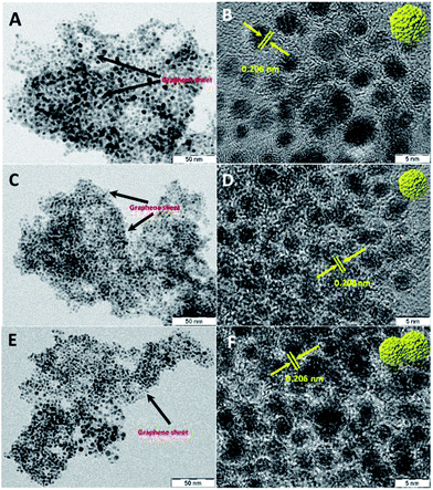 | ||
Fig. 1 TEM and HRTEM images of the NG-supported ultrafine Ru NCs synthesized via pyrolysing different ratios of DCA and Ru3+. (A and B) 10![[thin space (1/6-em)]](https://www.rsc.org/images/entities/char_2009.gif) : :![[thin space (1/6-em)]](https://www.rsc.org/images/entities/char_2009.gif) 1, (C and D) 4 1, (C and D) 4![[thin space (1/6-em)]](https://www.rsc.org/images/entities/char_2009.gif) : :![[thin space (1/6-em)]](https://www.rsc.org/images/entities/char_2009.gif) 1, and (E and F) 2 1, and (E and F) 2![[thin space (1/6-em)]](https://www.rsc.org/images/entities/char_2009.gif) : :![[thin space (1/6-em)]](https://www.rsc.org/images/entities/char_2009.gif) 1. 1. | ||
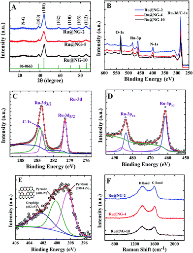
The formation of Ru NCs on NG was characterized via X-ray diffraction (XRD) and X-ray photoelectron spectroscopy (XPS). Fig. 2(A) displays the XRD patterns of Ru@NG-10, Ru@NG-4, and Ru@NG-2. The XRD peaks at the 2θ values 38.6, 44.1, 58.4, 69.3, 78.4, and 85.9° correspond to (100), (101), (102), (110), (103), and (112) crystal planes of hexagonal crystal structures (JCDPS#06-0663) of Ru, respectively. All the XRD patterns exhibited broad peaks around 25° that corresponded to the (002) crystal plane of graphene. Overall, the XRD results reveal the formation of Ru@NG via pyrolysis. The sizes estimated from the XRD peak (2θ = 44.1°) using Scherrer formula were ∼4.5, 2.0, and 2.8 nm for Ru@NG-10, Ru@NG-4, and Ru@NG-2, respectively, in good agreement with the TEM results. Fig. 2(B) displays the XPS survey spectra, which reveals the formation of Ru NCs and N-doped carbon nanostructures. Fig. 2(C and D) display the high resolution XPS spectra (HRXPS) of Ru-3d and 3p of the Ru@NG-4 hybrid. As observed from Fig. 2(C), two distinct peaks at the binding energies of 279.9 and 284.1 eV were observed that corresponded to Ru 3d5/2 and 3d3/2 with a spin orbit coupling of 4.2 eV.40 As is well-known, the area ratio between 3d5/2 and 3d3/2 is 3![[thin space (1/6-em)]](https://www.rsc.org/images/entities/char_2009.gif) :
:![[thin space (1/6-em)]](https://www.rsc.org/images/entities/char_2009.gif) 2. In contrast, the Ru 3d3/2 peak is broader as well as of higher intensity as compared to the d5/2 peak due to overlapping with the C-1s (284.6) contribution. The de-convoluted spectrum of Ru 3d3/2 shows clear contribution of C-1s as well. The binding energy of both Ru-3d peaks is 0.1 eV higher as compared to that of the bare Ru, whereas that of the C-1s peak is 0.1 eV lower as compared to that of the pure C-1s (284.6 eV). The peak shifting clearly signifies the strong interaction between the metallic Ru and carbon. The ratio between N–C and Ru is 76
2. In contrast, the Ru 3d3/2 peak is broader as well as of higher intensity as compared to the d5/2 peak due to overlapping with the C-1s (284.6) contribution. The de-convoluted spectrum of Ru 3d3/2 shows clear contribution of C-1s as well. The binding energy of both Ru-3d peaks is 0.1 eV higher as compared to that of the bare Ru, whereas that of the C-1s peak is 0.1 eV lower as compared to that of the pure C-1s (284.6 eV). The peak shifting clearly signifies the strong interaction between the metallic Ru and carbon. The ratio between N–C and Ru is 76![[thin space (1/6-em)]](https://www.rsc.org/images/entities/char_2009.gif) :
:![[thin space (1/6-em)]](https://www.rsc.org/images/entities/char_2009.gif) 24, which means that the Ru loading in the hybrid is ∼24 weight%, whereas Pt loading in Pt/C is 20 weight%. Similarly, the Ru-3p spectrum (Fig. 2(D)) shows two clear distinct peaks at 461.4 and 483.6 eV, corresponding to Ru-3p3/2 and 3p1/2, respectively, which is 0.4 eV higher compared to that of pure Ru-3p, signifying the interaction between metallic Ru and the underlying carbon layer.41,42 Additional small peaks at 464.1 and 486.3 eV indicate that there is a charge transfer from metallic Ru to C, which basically leads to better catalytic activity towards HER performances. Fig. 2(E) shows the HRXPS spectrum of the de-convoluted N 1s spectrum of Ru@NG-4. It contains mainly three different types of N environment: pyridine-type (398.4 eV), pyrrolic-type (400 eV), and graphite-type (401.9 eV). The % of N doping is ∼7.8% in the carbon framework, where 32% N is pyridinic, 34% N is pyrrolic, and the remaining 32% N is graphitic. Raman spectroscopy is a very effective tool to characterize graphene. Raman spectra shown in Fig. 2(F) clearly reveal the signature of carbon materials. Energy dispersive X-ray spectroscopy (EDS) was used to determine the presence of carbon in the Ru-NG hybrids as well as Ru loading (ESI-8†). Overall, the hybrids consist of NG-supported ultrafine Ru NCs (Ru@NG). On the basis of the experimental results, we proposed a possible growth mechanism for the ultrafine Ru@NG. DCA vaporises above 260 °C, whereas RuCl3·xH2O decomposes above 500 °C, which indicates that DCA vaporizes first and form the NG support for Ru NCs. The cyanide group in DCA is a source for carbon and nitrogen that forms NG via a condensation process. It has been suggested that carbon nitride gaseous fragments are released (such as C2N2+, C3N2+, and C3N3+) above 700 °C, which provides both C and N sources to form NG.43–45 Then, Ru3+ ions reduce in situ to ultrafine Ru NCs in the reducing environment. In this context, note that the formation of nitride or carbide is less probable as there is no source of nitrogen (there is no gas flow) and carbide formation requires high pressure.46 The size and dispersion of NCs strongly depend on the ratio between Ru3+ and DCA. When the ratio of DCA/Ru3+ is 10
24, which means that the Ru loading in the hybrid is ∼24 weight%, whereas Pt loading in Pt/C is 20 weight%. Similarly, the Ru-3p spectrum (Fig. 2(D)) shows two clear distinct peaks at 461.4 and 483.6 eV, corresponding to Ru-3p3/2 and 3p1/2, respectively, which is 0.4 eV higher compared to that of pure Ru-3p, signifying the interaction between metallic Ru and the underlying carbon layer.41,42 Additional small peaks at 464.1 and 486.3 eV indicate that there is a charge transfer from metallic Ru to C, which basically leads to better catalytic activity towards HER performances. Fig. 2(E) shows the HRXPS spectrum of the de-convoluted N 1s spectrum of Ru@NG-4. It contains mainly three different types of N environment: pyridine-type (398.4 eV), pyrrolic-type (400 eV), and graphite-type (401.9 eV). The % of N doping is ∼7.8% in the carbon framework, where 32% N is pyridinic, 34% N is pyrrolic, and the remaining 32% N is graphitic. Raman spectroscopy is a very effective tool to characterize graphene. Raman spectra shown in Fig. 2(F) clearly reveal the signature of carbon materials. Energy dispersive X-ray spectroscopy (EDS) was used to determine the presence of carbon in the Ru-NG hybrids as well as Ru loading (ESI-8†). Overall, the hybrids consist of NG-supported ultrafine Ru NCs (Ru@NG). On the basis of the experimental results, we proposed a possible growth mechanism for the ultrafine Ru@NG. DCA vaporises above 260 °C, whereas RuCl3·xH2O decomposes above 500 °C, which indicates that DCA vaporizes first and form the NG support for Ru NCs. The cyanide group in DCA is a source for carbon and nitrogen that forms NG via a condensation process. It has been suggested that carbon nitride gaseous fragments are released (such as C2N2+, C3N2+, and C3N3+) above 700 °C, which provides both C and N sources to form NG.43–45 Then, Ru3+ ions reduce in situ to ultrafine Ru NCs in the reducing environment. In this context, note that the formation of nitride or carbide is less probable as there is no source of nitrogen (there is no gas flow) and carbide formation requires high pressure.46 The size and dispersion of NCs strongly depend on the ratio between Ru3+ and DCA. When the ratio of DCA/Ru3+ is 10![[thin space (1/6-em)]](https://www.rsc.org/images/entities/char_2009.gif) :
:![[thin space (1/6-em)]](https://www.rsc.org/images/entities/char_2009.gif) 1 (Ru@NG-10), Ru NCs of 4–5 nm are obtained, whereas ultrafine ∼2 nm Ru NCs are formed when the ratio is 4
1 (Ru@NG-10), Ru NCs of 4–5 nm are obtained, whereas ultrafine ∼2 nm Ru NCs are formed when the ratio is 4![[thin space (1/6-em)]](https://www.rsc.org/images/entities/char_2009.gif) :
:![[thin space (1/6-em)]](https://www.rsc.org/images/entities/char_2009.gif) 1, and agglomerated structures consisting of primary particles of ∼2 nm are obtained for DCA/Ru3+ = 2
1, and agglomerated structures consisting of primary particles of ∼2 nm are obtained for DCA/Ru3+ = 2![[thin space (1/6-em)]](https://www.rsc.org/images/entities/char_2009.gif) :
:![[thin space (1/6-em)]](https://www.rsc.org/images/entities/char_2009.gif) 1. With low amount of RuCl3·xH2O, the size of the primary particles is believed to be below 2 nm that sintered together to form bigger particles (Fig. 3(A and B)). As the amount of RuCl3·xH2O is increased, the particle size becomes around 2 nm, and the particles are thermodynamically stable, as evident from the TEM images (Fig. 3(C and D)). As the amount is increased further, 2 nm particles form and aggregate, as is evident from the TEM images (Fig. 3(E and F)). This is well-supported by the increase in size as the temperature is increased. For a ratio of 4
1. With low amount of RuCl3·xH2O, the size of the primary particles is believed to be below 2 nm that sintered together to form bigger particles (Fig. 3(A and B)). As the amount of RuCl3·xH2O is increased, the particle size becomes around 2 nm, and the particles are thermodynamically stable, as evident from the TEM images (Fig. 3(C and D)). As the amount is increased further, 2 nm particles form and aggregate, as is evident from the TEM images (Fig. 3(E and F)). This is well-supported by the increase in size as the temperature is increased. For a ratio of 4![[thin space (1/6-em)]](https://www.rsc.org/images/entities/char_2009.gif) :
:![[thin space (1/6-em)]](https://www.rsc.org/images/entities/char_2009.gif) 1, the particle size is 2 nm at a pyrolysis temperature of 900 °C, whereas it becomes 5 nm at 1000 °C (ESI-Fig. 13A and B†).
1, the particle size is 2 nm at a pyrolysis temperature of 900 °C, whereas it becomes 5 nm at 1000 °C (ESI-Fig. 13A and B†).
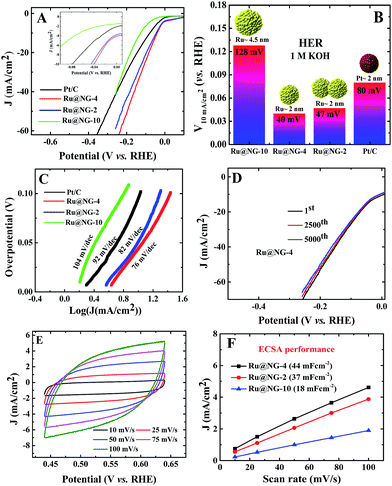
The electrocatalytic HER performance of Ru@NG was investigated in a N2-purged 1 M KOH and 1 M H2SO4 solutions as an alkaline and acidic electrolyte, respectively, using a three electrode setup with a Pt wire as the counter electrode and Ag/AgCl as the reference electrode. A commercial Pt/C catalyst was used for comparison of the catalytic performances in both acid and alkaline media. All the Ru@NG hybrids were placed on a glassy carbon electrode (GCE). Fig. 3(A) displays the HER polarization curves for different catalysts in a 1 M KOH solution. It is evident from the inset of Fig. 3(A) that all Ru@NG catalysts show zero onset potential as in the case of Pt/C, indicating that all Ru@NG catalysts are very active towards HER in an alkaline medium. Fig. 3(B) displays the relative potential required to achieve a current density of 10 mA cm−2, which is 40, 47, 128, and 80 mV for Ru@NG-4, Ru@NG-2, Ru@NG-10, and Pt/C catalysts, respectively. Ru@NG-4 shows the best HER performance as compared to other Ru@NG catalysts as well as Pt/C. It requires only 40 mV overpotential to obtain a 10 mA cm−2 current density, which is half that required for Pt/C. Fig. 3(C) compares the Tafel slope of all the catalysts in an alkaline medium. The Tafel slope of the catalysts are 76, 82, 104, and 92 mV dec−1 for Ru@NG-4, Ru@NG-2, Ru@NG-10, and Pt/C, respectively, which indicates high HER activity for Ru@NG-4. The Ru@NG-4 also shows very good stability towards HER. Fig. 3(D) displays that the catalyst is stable up-to 5000th cycle with almost no change in the current density (retention of 95% current density). Chronoamperometry measurements also reveal the long-term stability of Ru@NG-4 up-to 10 h (ESI-9†) in an alkaline medium. When a bias was applied, large H2 bubbles were clearly observed to have accumulated on the electrode surface (ESI-10†).
To shed more light on the catalytic activity of Ru@NG, the electrochemical double layers capacitance (Cdl), which is directly proportional to the electrochemical active surface area (ECSA), is evaluated. The ECSA was determined via cyclic voltammetry (CV) measurements in a non-redox regime in a 1 M KOH solution at different scan rates (Fig. 3(E)). It can be seen that Cdl of Ru@NG-4 is 44 mF cm−2, whereas that of Ru@NG-2 and Ru@NG-10 is 37 and 18 mF cm−2 (Fig. 3(F)), respectively. This result indicates that the electrochemically active sites of Ru@NG-4 towards HER are high due to ultrafine size and monodispersion of Ru NCs on NG. The large value of ECSA provides additional active sites and simplifies the charge transfer in the catalyst to the electrode,27 which is evident from the variation of current density with Cdl (ESI-11†).
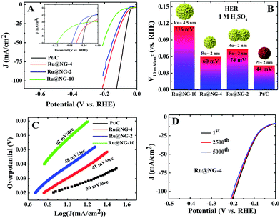
Fig. 4(A) shows the polarization curves of different catalysts in an acidic (1 M H2SO4) solution. It is evident from the inset of Fig. 3(E) that all the Ru@NG catalysts show zero onset-potential as in the case of Pt/C. Fig. 4(B) displays the potential required to achieve a current density of 10 mA cm−2, which is 60, 74, 116, and 40 mV for Ru@NG-4, Ru@NG-2, Ru@NG-10, and Pt/C, respectively. Ru@NG-4 catalyst shows very promising HER activity in an acidic medium as well. Fig. 4(C) compares the Tafel slope of all the catalysts in an acid medium. The Tafel slope of all the catalysts are 41, 48, 62, and 30 mV dec−1 for Ru@NG-4, Ru@NG-2, Ru@NG-10, and Pt/C, respectively, and η is zero. These results suggest that the recombination of two adsorbed H atoms is the rate limiting step and follow the Tafel mechanism. As evident from Fig. 4(D), the Ru@NG-4 catalyst is very stable up-to 5000th cycle (retention of 97% current density) and far superior compared to Pt/C, as in the case of an alkaline medium. This is believed to be due to better adhesion of Ru NCs on an NG support. Overall, the catalytic activity of all the Ru@NG catalysts and Pt/C is presented in Table S-2.† The mass and Cdl (considered to be proportional to the electrochemical surface area) normalized HER current density of all Ru@NG is shown in ESI-12.† Note that Ru@NG-4 and Ru@NG-2 have almost the same Cdl normalized HER activity. The Ru@NG-4 hybrid materials synthesized at different temperatures also support the size/morphology-dependent HER activity (ESI-13–15†). Overall, HER activity strongly depends on NC size as well as the dispersion on N-G substrate. Ru@NG-4 with ultrafine (∼2 nm) Ru NCs on the NG shows excellent HER performances. Although Ru@NG-2 also consists of primary particles with ∼2 nm size, the catalytic performance is below Ru@NG-4 due to the agglomerated structures. The Ru@NG-10 catalyst shows very poor catalytic activity compared to the other two catalysts due to the bigger Ru NCs (4–5 nm) and lower ECSA. Electrochemical impedance spectroscopy (EIS) was carried out to evaluate the electrochemical behaviour under HER operation (ESI-16†). The charge transfer resistance (Rct) of Ru@NG-4 and Ru@NG-2 was determined to be only 6 and 8 ohm, respectively, which indicates facile H+ reduction at the electrode–electrolyte interface.23 The results suggest that that nicely dispersed and strongly attached ultrafine particles are essential for excellent HER performances. As compared to the literature-reported HER catalyst, Ru@NG-4 is one of the most exciting catalysts towards the HER performances (Table S-3†) and has true potential to replace the 25-times costlier precious Pt (Table S-4†).
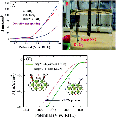
To elucidate the potential of Ru@NG, an alkaline electrolyzer (1.0 M KOH) employing commercial C paper, commercial Pt/C, and our Ru@NG as cathode catalysts and RuO2 as the anode catalyst was constructed. As shown in Fig. 4(A), the Pt/C–RuO2 and Ru@NG-RuO2 couples catalyze water electrolysis at an onset potential of ∼1.45 V with an overpotential (η) of only 220 mV. A current density at ∼50 mA cm−2 was obtained at 1.67 V for both Ru@NG-RuO2 and Pt/C–RuO2; however, better current density for the former case was obtained beyond 1.67 V. For example, the current density was 100 mA cm−2 at 1.84 V for Ru@NG-RuO2, whereas it was 92 mA cm−2 for Pt/C–RuO2. Furthermore, the Ru@NC couple exhibited excellent stability, as manifested by the steady current change and nearly linear charge accumulation for 10 h of electrolysis at η = 360 mV and stable up-to 2500th cycle (ESI-17†). Fig. 4(B) displays the optical image of the generation of H2 and O2via water electrolysis (video of water splitting has been provided at 1.67 V). To probe the role and the catalytic site of Ru@NG, the sample is treated with thiocyanate (SCN−) ions as it is widely known to poison metal-centred catalytic sites and influence the HER performance.47 After the treatment of SCN− into the basic electrolyte (50 mM), the overpotential increased from 0 to 10 mV; moreover, the overpotential also significantly increased from 44 mV to 74 mV to achieve 10 mA cm−2 (Fig. 4(C)). This study suggests that the HER catalytic active sites of Ru are blocked by the SCN− ions, effectively decreasing the HER performance (Fig. 5(C)).
In conclusion, we synthesized Ru@NG via one-step pyrolysis for the first time and demonstrated it as a novel and emerging HER catalyst in both acid and alkaline media. The HER performances strongly depend on the size of Ru NCs and its dispersion on the graphene support; they outperform the HER activity of the precious Pt catalysts and have the potential to replace them. Overall, it is believed that this synthesis technique can be explored for various other hybrids with ultrafine NCs and their suitability in various applications.
Acknowledgements
The authors acknowledge the Department of Science and Technology (DST) and Council of Scientific and Industrial Research (CSIR) India for the financial support. The authors also acknowledge Chemical Science Division in IISc for providing access to FETEM facility.References
- A. J. Bard and M. A. Fox, Acc. Chem. Res., 1995, 28, 141–145 CrossRef CAS.
- C. Li and Y. Yamauchi, Phys. Chem. Chem. Phys., 2013, 15, 3490–3496 RSC.
- H. A. Esfahani, M. Imura and Y. Yamauchi, Angew. Chem., Int. Ed., 2013, 52, 13611–13615 CrossRef PubMed.
- C. Li, T. Sato and Y. Yamauchi, Angew. Chem., Int. Ed., 2013, 52, 8050–8053 CrossRef CAS PubMed.
- J. A. Turner, Science, 2004, 305, 972–974 CrossRef CAS PubMed.
- S. M. Dresselhaus and I. L. Thomas, Nature, 2001, 414, 332–337 CrossRef PubMed.
- X. Ge, L. Chen, L. Zhang, Y. Wen, A. Hirata and M. Chen, Adv. Mater., 2014, 26, 3100–3104 CrossRef CAS PubMed.
- M. Zeng and Y. Li, J. Mater. Chem. A, 2015, 3, 14942–14962 CAS.
- J. Kibsgaard, C. Tsai, K. Chan, J. D. Benck, J. K. Nørskov, F. A. Pedersen and T. F. Jaramillo, Energy Environ. Sci., 2015, 8, 3022–3029 CAS.
- P. C. K. Vesborg, B. Seger and I. B. Chorkendorff, J. Phys. Chem. Lett., 2015, 6, 951–957 CrossRef CAS PubMed.
- J. R. McKone, E. L. Warren, M. J. Bierman, S. W. Boettcher, B. S. Brunschwig, N. S. Lewis and H. B. Gray, Energy Environ. Sci., 2011, 4, 3573–3583 CAS.
- J. Greeley, T. F. Jaramillo, J. Bonde, I. Chorkendorff and J. K. Norskov, Nat. Mater., 2006, 5, 909–913 CrossRef CAS PubMed.
- J. Kibsgaard, Z. Chen, B. N. Reinecke and T. F. Jaramillo, Nat. Mater., 2012, 11, 963–969 CrossRef CAS PubMed.
- D. Voiry, M. Salehi, R. Silva, T. Fujita, M. Chen, T. Asefa, V. B. Shenoy, G. Eda and M. Chhowalla, Nano Lett., 2013, 13, 6222–6227 CrossRef CAS PubMed.
- M. Chhetri, S. Maitra, H. Chakraborty, U. V. Waghmare and C. N. R. Rao, Energy Environ. Sci., 2016, 9, 95–101 CAS.
- M. A. Lukowski, A. S. Daniel, C. R. English, F. Meng, A. Forticaux, R. J. Hamers and S. Jin, Energy Environ. Sci., 2014, 7, 2608–2613 CAS.
- L. Cheng, W. J. Huang, Q. F. Gong, C. H. Liu, Z. Liu, Y. G. Li and H. J. Dai, Angew. Chem., Int. Ed., 2014, 53, 7860–7863 CrossRef CAS PubMed.
- S. T. Hunt, T. Nimmanwudipong and Y. Román-Leshkov, Angew. Chem., Int. Ed., 2014, 53, 5131–5136 CAS.
- E. J. Popczun, J. R. McKone, C. G. Read, A. J. Biacchi, A. M. Wiltrout, N. S. Lewis and R. E. Schaak, J. Am. Chem. Soc., 2013, 135, 9267–9270 CrossRef CAS PubMed.
- E. J. Popczun, C. G. Read, C. W. Roske, N. S. Lewis and R. E. Schaak, Angew. Chem., Int. Ed., 2014, 53, 5427–5430 CrossRef CAS PubMed.
- J. Q. Tian, Q. Liu, A. M. Asiri and X. P. Sun, J. Am. Chem. Soc., 2014, 136, 7587–7590 CrossRef CAS PubMed.
- J. Tian, Q. Liu, N. Cheng, A. M. Asiri and X. Sun, Angew. Chem., Int. Ed., 2014, 53, 9577–9581 CrossRef CAS PubMed.
- D. Das and K. K. Nanda, Nano energy, 2016, 30, 303–311 CrossRef CAS.
- Y. G. Li, H. L. Wang, L. M. Xie, Y. Y. Liang, G. S. Hong and H. Dai, J. Am. Chem. Soc., 2011, 133, 7296–7299 CrossRef CAS PubMed.
- X. Huang, Z. Y. Zeng and H. Zhang, Chem. Soc. Rev., 2013, 42, 1934–1946 RSC.
- M. Gong, W. Zhou, M. C. Tsai, J. G. Zhou, M. Y. Guan, M. C. Lin, B. Zhang, Y. F. Hu, D. Y. Wang, J. Yang, S. J. Pennycook, B. J. Hwang and H. J. Dai, Nat. Commun., 2014, 5, 4695 CrossRef CAS PubMed.
- H. Jin, J. Wang, D. Su, Z. Wei, Z. Pang and Y. Wang, J. Am. Chem. Soc., 2015, 137, 2688–2694 CrossRef CAS PubMed.
- H. Zhu, J. Zhang, R. Yanzhang, M. Du, Q. Wang, G. Gao, J. Wu, G. Wu, M. Zhang, B. Liu, J. Yao and X. Zhang, Adv. Mater., 2015, 27, 4752–4759 CrossRef CAS PubMed.
- J. Wang, W. Cui, Q. Liu, Z. Xing, A. M. Asiri and X. Sun, Adv. Mater., 2016, 28, 215–230 CrossRef CAS PubMed.
- S. T. Hunt, M. Milina, Z. Wang and Y. R. Leshkov, Energy Environ. Sci., 2016, 9, 3290–3301 CAS.
- K. Kusada, H. Kobayashi, T. Yamamoto, S. Matsumura, N. Sumi, K. Sato, K. Nagaoka, Y. Kubota and H. Kitagawa, J. Am. Chem. Soc., 2013, 135, 8016–8021 CrossRef PubMed.
- J. Ohyama, T. Sato, Y. Yamamoto, S. Arai and A. Satsuma, J. Am. Chem. Soc., 2013, 135, 8016–8021 CrossRef CAS PubMed.
- H. Bielawa, O. Hinrichsen, A. Birkner and M. Muhler, Angew. Chem., Int. Ed., 2001, 40, 1061–1063 CrossRef CAS PubMed.
- C. S. Kellner and A. T. Bell, J. Catal., 1982, 75, 251 CrossRef CAS.
- J. Kang, S. Zhang, Q. Zhang and Y. Wang, Angew. Chem., Int. Ed., 2009, 48, 2565 CrossRef CAS PubMed.
- T. Mitsudome, Y. Takahashi, T. Mizugaki, K. Jitsukawa and K. Kaneda, Angew. Chem., Int. Ed., 2014, 53, 8348–8351 CrossRef CAS PubMed.
- R. A. Dagle, Y. Wang, G.-G. Xia, J. J. Strohm, J. Holladay and D. R. Palo, Appl. Catal., A, 2007, 326, 213 CrossRef CAS.
- T. Abe, M. Tanizawa, K. Watanabe and A. Taguchi, Energy Environ. Sci., 2009, 2, 315 CAS.
- K. Urasaki, K. Endo, T. Takahiro, R. Kikuchi, T. Kojima and S. Satokawa, Top. Catal., 2010, 53, 707 CrossRef CAS.
- D. J. Morgan, Surf. Interface Anal., 2015, 47, 1072 CrossRef CAS.
- M. Tang, S. Mao, M. Li, Z. Wei, F. Xu, H. Li and Y. Wang, ACS Catal., 2015, 5, 3100–3107 CrossRef CAS.
- Y. Zheng, Y. Jiao, Y. Zhu, L. H. Li, Y. Han, Y. Chen, M. Jaroniec and S.-Z. Qiao, J. Am. Chem. Soc., 2016, 138, 16174–16181 CrossRef CAS PubMed.
- Z. Wen, S. Ci, Y. Hou and J. Chen, Angew. Chem., Int. Ed., 2014, 53, 6496–6500 CrossRef CAS PubMed.
- Y. Hou, Z. Wen, S. Cui, S. Ci, S. Mao and J. Chen, Adv. Funct. Mater., 2015, 25, 872–877 CrossRef CAS.
- B. K. Barman and K. K. Nanda, Green Chem., 2016, 18, 427–432 RSC.
- E. Zhao, J. Wang and Z. Wu, J. Comput. Chem., 2010, 31, 2883–2888 CAS.
- H. W. Liang, S. Bruller, R. Dong, J. Zhang, X. Feng and K. Mullen, Nat. Commun., 2015, 6, 7992 CrossRef CAS PubMed.
Footnote |
| † Electronic supplementary information (ESI) available. See DOI: 10.1039/c7se00153c |
| This journal is © The Royal Society of Chemistry 2017 |

