
Investigation of the reaction mechanism of lithium sulfur batteries in different electrolyte systems by in situ Raman spectroscopy and in situ X-ray diffraction†
W.
Zhu
a,
A.
Paolella
a,
C.-S.
Kim
a,
D.
Liu
a,
Z.
Feng
a,
C.
Gagnon
a,
J.
Trottier
a,
A.
Vijh
a,
A.
Guerfi
a,
A.
Mauger
b,
C. M.
Julien
c,
M.
Armand
d and
K.
Zaghib
 *a
*a
aEnergy Storage and Conversion, Research Institute of Hydro-Québec, Varennes, Québec, Canada J3X 1S1. E-mail: zaghib.karim@ireq.ca; Fax: +1 450 652 8424; Tel: +1 450 652 8019
bUniversité Pierre et Marie Curie – Paris6, Institut de Minéralogie et Physique de la Matière Condensée (IMPMC), 4 place Jussieu, 75005 Paris, France
cUniversité Pierre et Marie Curie – Paris6, Physicochimie des Electrolytes, Colloïdes et Sciences Analytiques (PECSA), UMR 7195, 4 place Jussieu, 75005 Paris, France
dCIC Energygune, Parque Tecnologico de Alava, Albert Einstein 48, Ed. CIC, 01510 Minano, Spain
First published on 7th March 2017
Abstract
Lithium–sulfur batteries are of great interest owing to their high theoretical capacity of 1675 mA h g−1 and low cost. Their discharge mechanism is complicated and it is still a controversial issue. In the present work, in situ Raman spectroscopy is employed to investigate the poly-sulfide species in the sulfur cathode and in the electrolyte during the cycling of Li–S batteries. The aim is to understand the discharge mechanism and the influence of the electrolyte on the dissolution of sulfur and poly-sulfides. S8n− is identified as the main species in the high voltage plateau of discharge together with cycloocta S8, in the cell using 0.5 mol L−1 LiTFSI–PY13–FSI as the electrolyte. S42−, S22− and S2− are detected soon after the low voltage plateau is reached. A discharge mechanism in the PY13–FSI is proposed based on the identified species which provides important information for improving and designing cathodes. Electrolytes of 0.5 mol L−1 LiTFSI–PY13–FSI and 1 mol L−1 LiTFSI–DOL–DME are used in studying the dissolution of sulfur and poly-sulfides. The results demonstrate that the same poly-sulfide species are present in the two electrolytes. However, the rates of poly-sulfide formation and diffusion to the anode are slow in the ionic liquid compared to those in the ether-based electrolyte due to different ionic mobilities of various species in the two electrolytes. These differences are evidenced by the observation of poly-sulfide species in the DOL–DME from the very beginning of cell assembly even before starting the discharge whereas their appearances, in the ionic liquid, are delayed and only found at the end of the high voltage plateau. Notably, the soluble elemental sulfur is clearly observed in the ionic liquid electrolyte during the first discharge in the high voltage region, which is very different from the DOL–DME system where the elemental sulfur is quickly reduced to poly-sulfides due to self-discharge reactions. In addition, the elemental sulfur is also detected near the lithium anode in DOL–DME at the end of charge, for the first time to our knowledge, which suggests that the degradation of lithium metal is caused by the multiple reactions of the lithium metal surface with soluble poly-sulfides and/or elemental sulfur.
1. Introduction
Lithium–sulfur rechargeable batteries are one of the most promising candidates for various applications owing to their high theoretical energy density (2600 Wh kg−1), high theoretical capacity (1675 mA h g−1), good safety, natural abundance and low cost. Despite these advantages, the present performance of Li–-S batteries, such as in terms of rate capability, energy density and cyclability, is unable to meet the requirements for practical applications due to the following shortcomings:1–6(1) Low electrical conductivity of sulfur (10−18 S cm−1 (ref. 7)); the insulating properties result in low rate capability, as well as low sulfur loading owing to the addition of large amounts of conductive materials.
(2) Dissolution of sulfur8 and poly-sulfides in the electrolyte that causes the loss of active material results in shuttle reactions of poly-sulfides between the cathode and anode, which contribute to the deterioration of the lithium anode. The shuttling also deposits quasi insulating Li2S (∼10−13 S cm−1 (ref. 9)) on the anode surface, which increases the cell resistance leading to rapid capacity fading.
(3) The large volume change during cycling induced by density differences between sulfur (2.03 g cm−1 (ref. 10)) and lithium sulfide (1.63 g cm−1 (ref. 10)) fractures the positive electrode and reduces its capacity.
(4) Depletion of the electrolyte over cycling due to irreversible side reactions.
To overcome these difficulties, recently, many efforts have been devoted to comprehending the mechanism of the charge–discharge process for designing and improving cathode materials for Li–S batteries. The high theoretical capacity of Li–S batteries is based on the electrochemical reduction of cycloocta S8 to Li2S, i.e., one S8 ring hosts 16 Li+ ions at the end of discharge: this is a stepwise process involving different lithium poly-sulfides as intermediate phases. It is commonly believed that the long chain poly-sulfides, Li2Sn (n = 8–6), are mainly responsible for the first discharge plateau at ∼2.4 V, whereas the short chain poly-sulfides Li2Sn (n = 4–1) are the main species involved in the second plateau at ∼2.1 V.11,12 However, the exact mechanism is still not totally understood due to the discrepancies in the intermediate poly-sulfide phases formed and their corresponding potentials, as reported by various groups. These differences in the observed data originate from the complexity of the electrochemical and chemical reactions involved, as well as from the sensitivity of the sulfur and poly-sulfides to the experimental conditions and their environment, such as the electrolyte.13,14 Many studies were focused on the complex discharge/charge mechanism via various characterisation techniques, especially the in operando ones that provide electrode information as the battery is cycling. Several groups have studied the phase transformation of the sulfur cathode by in situ X-ray diffraction (XRD). Walus et al.15 observed the co-existence of α-sulfur and β-sulfur during charge and Li2S during discharge. In addition, Cãnas et al.16 found that the sulfur phase obtained after charge was different from the initial sulfur structure, but no phase identification was reported. Recently, crystalline Li2S2 was identified for the first time under solvent-in-salt electrolyte conditions.17 In contrast to Walus' findings, Nelson and co-workers18 did not detect the formation of crystalline Li2S during discharge; they also suggested that the recrystallization of sulfur at the end of the charge cycle depended on the preparation methods of the cathode (such as the carbon surface area, sulfur particle size, etc.). However, the non-crystalline nature of the intermediate phases in the Li–S battery makes their identification with XRD impossible. Other techniques, therefore, must be employed. Patel et al.19 recorded the Ultraviolet-Visible (UV/Vis) spectrum evolution of a Li–S battery during cycling; they identified that Li2S8 and Li2S6 existed at the high voltage plateau, while Li2S4 and Li2S3 were dominant at the low voltage one, and Li2S2 and Li2S were the principal species when the voltage was lower than the low voltage plateau (∼2 V). Using a polymer electrolyte that partially reduces the dilution of the catholyte, the in operando measurements yielded UV-vis absorption bands that are well resolved, which improved our understanding of the spectra and identification of the various sulfur species present at different steps of the charge–discharge cycles. In particular, these measurements gave evidence that the charge and discharge mechanisms mostly differ by the formation of S42− during discharge and S62− during charge.20 The poly-sulfides present during cycling were also characterised by in operando X-ray Absorption Spectroscopy (XAS).21 Cuisinier et al.14,22 identified S8/S82− and S62− species at the 2.4 V discharge plateau, whereas S62− and S42− were intermediate species at the 2.1 V plateau in the mixture of low dielectric solvents 1,3-dioxolane and 1,2-dimethoxyethane (DOL–DME). On the other hand, the S3˙− radical and S42− were detected in high dielectric constant solvents including dimethylacetamide (DMA) and others as reviewed in ref. 13. Their results demonstrated that the intermediate poly-sulfides were closely related to the choice of the electrolyte and that of the solvent in particular. Wujcik and co-workers23 observed that Li2S6, LiS5 and S8 were dominant from the open circuit voltage to 2.25 V; Li2S, Li2S3/5 and Li2S6/8 were the main species from 2.25 to 2.02 V, whereas Li2S, Li2S2 and Li2S5 increased as the discharge proceeded to 1.5 V. The in situ Raman spectroscopy technique is also effective in examining the transitional species during cycling.24,25 Hagen et al.26 have calculated the Raman band positions of various mono-anions and di-anions of poly-sulfides with Density Functional Theory (DFT). Combining the DFT calculation and in situ Raman measurements on a Li–S cell with several electrolytes, they proposed that there were polysulfide mono-anions next to di-anions in every state of charge. However, identifying the exact species in the experimental spectra is challenging due to the difficulty in de-convoluting the overlapped bands. With the same calculation and experimental technique, Hannauer and co-workers27 indicated that Sn2− species (n = 6, 8) peaked near the end of the ∼2.4 V plateau. They also observed that the intensity of the S3˙− band was highest just before the beginning of the 2.1 V plateau in the cell using TEGDME (glycol dimethyl ether)–DOL as the electrolyte. In addition, the S3˙− and S2O42−, together with S42− and S4− were observed by Wu et al.28 in the cell using the same electrolyte. Other techniques, such as Fourier transform infrared spectroscopy (FTIR),29 Electron Paramagnetic Resonance (EPR)12 and High Performance Liquid Chromatography (HPLC)11 were also used to detect and identify the intermediate species formed during cycling. Wild et al.30 reviewed various analytical studies and physical models, and brought together recent advances in the mechanistic understanding of the Li–S battery. They suggested that this understanding was still hindered by the limitations of available techniques and the dependence of the mechanism on cell design. In addition the experimental analysis did not consider spatial aspects of the mechanism, as chemically much of it is envisaged in the electrolyte whilst electrochemical reactions occurred at surfaces.
In the present work, we employed in situ Raman spectroscopy to monitor the evolution of poly-sulfide species both on sulfur cathode surfaces and in electrolytes near the Li anode aiming at extending our knowledge in spatial aspects of the battery; in addition, we used in-situ XRD to follow the crystalline phase transformation in the cathode phase to elucidate the reaction mechanism during galvanostatic cycling. Ultimately, the information obtained will be useful for designing and improving Li–S batteries.
2. Experimental
2.1 Electrode preparation
Sulfur (purity > 99![[thin space (1/6-em)]](https://www.rsc.org/images/entities/char_2009.gif) 998%, Sigma Aldrich) and Ketjen Black (AkzoNobel) were ground in a mortar. A slurry was prepared with a mixture of sulfur, Ketjen Black and PVDF binder (KF7305, Kureha) at a ratio of 60:30:10 in a SPEX mixer using N-methyl pyrrolidone (NMP, purity > 99.5%, Sigma Aldrich) as the solvent. The slurry was first coated on one side of an aluminium mesh via a doctor blade method, and then dried at 75 °C, followed by the coating and drying of the second side.
998%, Sigma Aldrich) and Ketjen Black (AkzoNobel) were ground in a mortar. A slurry was prepared with a mixture of sulfur, Ketjen Black and PVDF binder (KF7305, Kureha) at a ratio of 60:30:10 in a SPEX mixer using N-methyl pyrrolidone (NMP, purity > 99.5%, Sigma Aldrich) as the solvent. The slurry was first coated on one side of an aluminium mesh via a doctor blade method, and then dried at 75 °C, followed by the coating and drying of the second side.
2.2 Electrochemical cell preparation and measurements
The in situ Raman cells were made from a 2030 coin cell with a 0.15 mm thick quartz plate as the window. The electrochemical cells consist of a sulfur electrode with aluminium mesh as the current collector, a separator (Celgard 3501 or Whatman glass microfiber filters Grade GF/C), a lithium counter electrode and an electrolyte. Two types of electrolytes were used: (a) 0.5 mol L−1 LiTFSI (lithium bis-(trifluoromethylsulfonyl)imide) dissolved in PY13 (N-methyl-N-propylpyrrolidinium)–FSI (bis(fluorosulfonyl)imide) and (b) 1 mol L−1 LiTFSI dissolved in DOL–DME (DOL:DME = 1:1, v/v). The solid components were dried at 120 °C overnight under vacuum except for the cathode which was dried at 55 °C for 3 hours under low vacuum. The cells were then assembled in a helium-filled glovebox with two configurations. For studying the changes of the sulfur cathode during the charge–discharge, the electrode was placed in contact with the cell window (Fig. 1a), whereas for monitoring the species in the electrolyte on the lithium side, a small hole was punched at the center of the lithium disk which was in contact with the quartz window, see Fig. 1b.
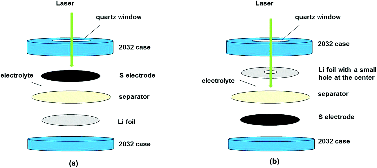 | ||
| Fig. 1 In situ Raman cell configurations for examining the changes in the (a) cathode and (b) electrolyte near Li metal. | ||
The in situ XRD cells were made from a 2030 coin cell with a 0.25 mm thick beryllium disk as the window. 1 mol L−1 LiTFSI dissolved in DOL–DME–2% LiNO3 was used as the electrolyte.
The electrochemical measurements were carried out on a Biologic SP300 (BioLogic Science Instrument), controlled by EC-Lab (V10.19), between 2.8 V and 1.0 V at slow rates of C/48–C/60.
2.3 In situ Raman spectroscopy and X-ray diffraction measurements
The in situ Raman measurements were performed on a LabRam Aramis Spectrometer (Horiba, Jobin Yvon) controlled by LabSpec 5. A laser beam of wavelength 532.1 nm and energy 0.14–1.22 mW, with a spot size of ∼ 2.6 μm, was focused with a 10× objective. The measurements were carried out in the wavenumber range of 50–800 cm−1 every 30 minutes with the data collection time varying between 600 and 45 seconds. The sulfur powder and cathode were also examined.The in situ XRD measurements were performed on a D8 Advance Diffractometer (Bruker) with Cu-Kα radiation from 21–38° at a step size of 0.025° and 18 s per step. The sulfur powder, electrode and beryllium disk (Fig. S1, ESI†) were also characterised by X-ray diffraction from 10° to 80°.
3. Results and discussion
3.1 Characterisation of sulfur powder
The sulfur powder was analyzed by X-ray diffraction prior to fabricating the electrode. All the diffraction peaks can be indexed to α-sulfur (PDF: 01-078-1888); the lattice parameters obtained from Rietveld refinement with a space group (S.G.) Fddd are: a = 10.46017(7), b = 12.86286(0), and c = 24.46326(0) (Fig. S2, ESI†). The crystallinity of the sulfur estimated with software DiffracEva (Bruker) is ∼76%, and its average crystal size is ∼60 nm as calculated by the Scherrer formula with the same software. The Raman spectrum of the powder shows a band at 79 cm−1 related to the torsion mode in sulfur, bands at 147, 180, 213, 241 cm−1 related to the bending mode and bands at 432 as well as 467 cm−1 related to the stretching mode31,32 (Fig. S3, ESI†).3.2 Characterisation of the electrochemical properties of the sulfur electrode
Several cells using both 0.5 mol L−1 LiTFSI–PY13–FSI and 1 mol L−1 LiTFSI–DOL–DME electrolytes were cycled at slow rates; the discharge capacities of the first cycle ranged from ∼700 to ∼1450 mA h g−1, see Fig. 2. In general, cells using ionic liquids have low capacities, which are due to (1) the slower mobility of ionic species in more viscous liquids; (2) poor electrode-wetting properties; (3) the lower solubility of sulfur redox intermediates, which is positive for inhibiting parasitic reactions but negative in terms of kinetics. Despite the low capacities of certain cells, the discharge curves still show the typical features of the sulfur reduction reaction. The high and low voltage plateaus were observed at ∼2.2 V and ∼2.03 V for the cells using ionic liquid, and ∼2.3 V and ∼2.1 V for those using DOL–DME. The high voltage plateau is generally believed to be related to the formation of long chain poly-sulfides (Li2Sn, n = 6–8), whereas the low voltage plateau is the result of the reduction of long chain poly-sulfides to the shorter ones.11,19,22 The voltage plateaus of the cells using PY13–FSI have lower values compared to those using DOL–DME, which suggests that it is more difficult to form poly-sulfide species in the ionic liquid owing to the low mobility of various species; therefore, more energy is required. The charge curves displayed only one voltage plateau with the mid values of ∼2.36 and ∼2.30 V for cells using 0.5 mol L−1 LiTFSI–PY13–FSI and 1 mol L−1 LiTFSI–DOL–DME, respectively. The cell using DOL–DME with addition of LiNO3 showed a high capacity of ∼1450 mA h g−1 which was attributed to the formation of a passivation layer on the Li surface and suppression of the redox shuttle of lithium poly-sulfides.33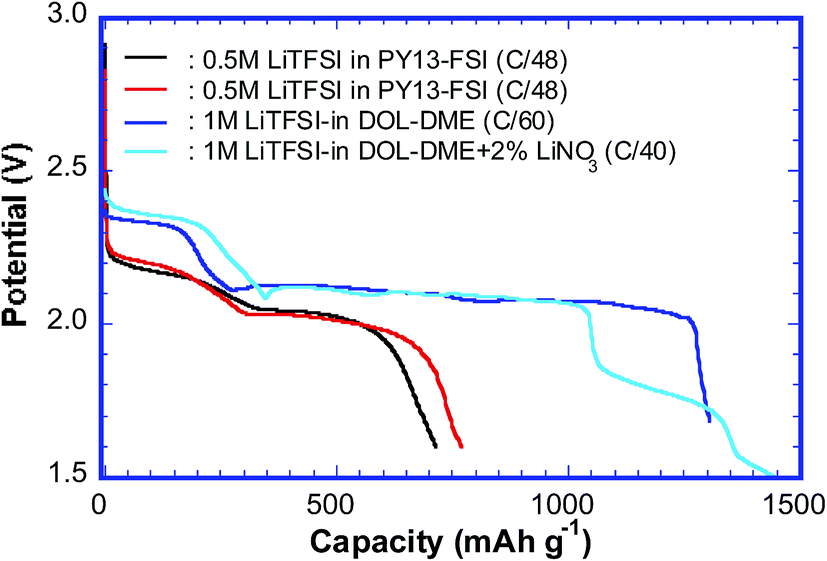 | ||
| Fig. 2 The capacities (first discharge cycle) obtained from the cells using PY13–FSI and DOL–DME as electrolytes. | ||
3.3 In situ Raman measurements
 | ||
| Fig. 3 A Li–S cell with 0.5 M LiTFSI–PY13–FSI as the electrolyte cycled at a rate of C/48. (a) Evolution of Raman spectra of the sulfur electrode, and the inset is enlarged Raman spectra at two different voltages of discharge; (b) zoomed-in image of the green areas in (a), plotted every 3 spectra; (c) the polysulfide species detected via Raman with their corresponding potentials. Red: discharge; blue: charge. (d) The intensity ratio of different species as a function of electric potential. | ||
The intensities of the sulfur bands decreased as the discharge proceeded and disappeared completely at the beginning of the low voltage plateau, ∼2.04 V (Fig. 3a), indicating that almost all the S8 rings were opened to form long chain poly-sulfides. This ring opening was initially observed on the high voltage plateau, ∼2.17 V; it was characterised by the formation of a band at 398 cm−1 which persisted up to ∼2.04 V (low voltage plateau) and was assigned to the S–S stretching mode in S8n− (n = 1, 2).36,37 In this voltage range, the electrochemical (EC) reaction is:
| S8 + nLi+ne− → LinS8 (n = 1, 2) | (EC-1) |
As discharge proceeded, small bands at ∼453, ∼201 and ∼490 cm−1 started to appear at the beginning of the low voltage plateau, ∼2.05 V, see Fig. 3b for clarity which shows plots every three spectra in the green areas of Fig. 3a. The 201 cm−1 band was assigned to the bending mode of S42−, and the 453 and 490 cm−1 bands were assigned to the stretching mode of S42−.39,40 The presence of S42− is widely observed with various analytical techniques despite the differences in the exact voltage intervals on the discharge curve. The S42− species was detected on the voltage slope between high and low voltage plateaus in some studies,11,28 whereas other investigators reported it on the low plateau.19 Again, the electrolytes used may play a role. The S42− species was detected before the beginning of the low voltage plateau in the cells with TEGDME–DOL; the earlier polysulfide formation in this electrolyte than in the ionic liquid, in our case, is attributed to the higher solubility of poly-sulfides in the ether-based solvent with lower viscosity and faster reduction of S82− to S42− in it.13 Although the dissolution of the active material in the electrolyte is not desired in the battery, the poly-sulfides in the liquid phase may accelerate the electrochemical and chemical reactions. In addition, S22− has its strongest band at ∼450 cm−1 (stretching mode);39,41,42 therefore, the 453 cm−1 band observed may have a certain contribution of S22− under these conditions. The small band at ∼360 cm−1 is probably related to the characteristic T2g phonon mode of Li2S corresponding to the Li–S stretching mode.43 Li2S is thus formed as the end product of discharge, despite the chemical disproportionation of various poly-sulfides proceeding concurrently. The bands at 453 and 201 cm−1 disappeared just before the end of discharge indicating that the S42− and S22− were consumed by the continuous formation of Li2S. The major electrochemical and chemical (C) reactions at the low voltage plateau are proposed as follows:
| Li2S8 + 2Li+ + 2e− → 2Li2S4 | (EC-2) |
| 2Li2S8 → 2Li2S4 + S8 | (C-1) |
| Li2S4 + 2Li+ + 2e− → 2Li2S2 | (EC-3) |
| Li2S2 + 2Li+ + 2e− → 2Li2S | (EC-4) |
| 3Li2S2 → Li2S4 + 2Li2S | (C-2) |
During the initial stage, the chemical reaction (C-1) was slow compared to (EC-1) and (EC-2), which was confirmed by the depletion of the S8 as the voltage reached 2.04 V where S8n− and S42− were the main species. Although S22− has its strongest band at ∼450 cm−1 close to the band of S42−(453 cm−1), its amount was small at the beginning of the low voltage plateau, which was supported by the high intensity of the band at 201 cm−1, characteristic of S42−. The ratio of I(201 cm−1)/I(453 cm−1) at this initial stage was ∼0.3, which continuously decreased as discharge proceeded, suggesting the increasing contribution of S22− to the 453 cm−1 peak (see Fig. 3a inset). As the discharge continued through the low voltage plateau, the main reactions are (EC-3), (EC-4) and (C-2), where disproportionation (C-2) was a slower process compared to the reduction reactions, as shown by the disappearance of S42−.
Just before the end of discharge, two more bands were observed, one at ∼392 cm−1 near 1.9 V followed by another at ∼430 cm−1 around 1.8 V; the former faded away before the end of discharge. Despite the S8n− band located near ∼392 cm−1, the formation of S82− from the disproportionation of S42− or S22− is energetically unfavorable based on the calculated results published.44 At present, it is difficult to determine the species corresponding to the two bands (marked as “?” in Fig. 3a).
The formation of poly-sulfide species during charge was almost a reverse process to the one observed during discharge, in spite of only one voltage plateau in the charge curve as reported by some researchers.27,45 The unidentified band at ∼430 cm−1 disappeared first as charge began. The bands of S42− and of S22− were observed at 201 and 453 cm−1 as soon as the voltage reached ∼2 V, and the characteristic band of Li2S (∼360 cm−1) vanished as the voltage reached the ∼2.2 V plateau via the oxidation from S2− to S22−. In addition, S8n− was observed at ∼2.3 V and persisted up to ∼2.6 V where the sulfur ring, S8, started to form and grew thereafter. The Raman investigation in the present study was not able to determine whether the cycloocta S8 formed during charge is in the orthorhombic (α-S8) or monoclinic (β-S8) crystal structure because the fundamental vibration bands of the two types of sulfur are indistinguishable in our spectrum range. The differences between the two allotropes lie in the range of Raman shift <100 cm−1.46,47Fig. 3c summarizes the observed poly-sulfide species with their corresponding potential profiles, which show that the S42− and S22− are reversibly coupled with the charge/discharge process. Four bands which have the least overlap with the other bands are selected to represent S2− (∼360 cm−1), S42− (∼200 cm−1), S8n− (∼390 cm−1) and S8 (∼217 cm−1) species. The intensity ratio of individual bands to the sum of the four bands is calculated as:
All the mechanisms proposed in literature on Li–S batteries obtained via the in situ Raman technique, involved the formation of the S3˙− anion radical that is different from the present studies which is related to the experimental conditions and electrolytes involved. Table 1 shows the electrolyte used and the corresponding poly-sulfide species detected as well as the mechanisms proposed.
| Authors | Electrolyte used | Species detected | Mechanism proposed |
|---|---|---|---|
| Hagen et al.26 | 0.7 M LiTFSI in DME–DOL (2:1) + 75 ppm BHT + 0.25 M/L LiNO3 |
OCV: | |
| S8 and possibly S72−, S8n− (n = 1, 2), S5− | |||
| Discharge: | |||
| • S3˙− | |||
| • Likely to have Sn2− (n = 2–7) | |||
| Charge: | |||
| Almost the reverse of discharge | |||
| Hannauer et al.27 | 1 M LiTFSI in TEGDME–DOL (1:1) |
Discharge: | Discharge: |
| S8, S82−/S62−, S3˙− | |||
| Charge: | • S8 → S82−/S62− → S3˙− + possibly other short chain PS → S2− | ||
| S3˙−, S82−/S62− | • Charge is a reverse process of discharge | ||
| Wu et al.28 | 1 M LiTFSI in TEGDME–DOL (1:1) |
Discharge: | 1st order reaction model |
| S8, S82−, S42−, S4−, S3˙−, Sn2− (n = 4–8), S2O42− | |||
| Charge: | • Short chain poly-sulfides are formed directly from S8 | ||
| S42−, S4−, S3˙−, S8, S82−, Sn2− (n = 4–8), S2O42− | • Charge and discharge are quasi-reversible and have similar rate constants | ||
| Yeon et al.25 | 1 M LiTFSI in | Discharge: | Discharge in TEGDME & TEGDME–DOL: |
| • TEGDME–DOL (4:6) |
• S8 + 2e− → S82− | ||
| • TEGDME | S8, Sn2− (n = 4–8), S2−, S3˙− | • S82− + ne− → (8/n) Sn2− (n = 4–8) | |
| • DOL | • 2S42− → 2S3˙− + S22− | ||
| Charge: | • S22− + 2e− → 2S2− | ||
| Discharge in DOL: | |||
| S2−, S3˙−, Sn2− (n = 4–8), S8 | • S8 + 2e− → S82− | ||
| • S82− + ne− → (8/n)Sn2− (n = 4–8) |
The Raman spectra from the cell using 0.5 mol L−1 LiTFSI PY13–FSI electrolyte are shown in Fig. 4a. All the bands in the initial spectrum were assigned to the electrolyte48 (Fig. S4, ESI†) indicating that no sulfur/poly-sulfide had diffused to the anode side before cycling began. As the discharge voltage decreased to ∼2.19 V, sulfur bands were observed at 149, 217 and 471 cm−1 and existed up to ∼2.09 V. This is the first time to report the solubility of elemental sulfur in the ionic liquid. Soon after detection of the sulfur bands, the initial broad band centred at ∼400 cm−1 (it can be de-convoluted into two peaks centered at ∼395 and 404 cm−1) increased in intensity at 2.13 V, especially the part at ∼395 cm−1 which is attributed to the formation of S8n−. The band at ∼433 cm−1 from the cell became enhanced and broadened, which can be de-convoluted into two peaks at 433 and 448 cm−1. The intensity of the 448 cm−1 peak increased as discharge proceeded. In addition, a band at 198 cm−1 was observed as the 448 cm−1 peak grew stronger; this pair of bands is associated with the S42−. The presence of high order poly-sulfides at the end of discharge indicates that the conversion of the active material is not complete with the utilization of active sulfur being inefficient. Towards the end of charge (V > 2.37 V), the intensities of the signals decreased and the spectra became noisy; it is difficult to discern any bands related to the cathode material. Throughout cycling, two types of poly-sulfide anions, S82− and S42−, were observed and at the end of charge, no elemental sulfur was detected. The species observed at the different stages of the cycling are labelled in Fig. 4b and their intensity ratios are plotted versus potential in Fig. 4c.
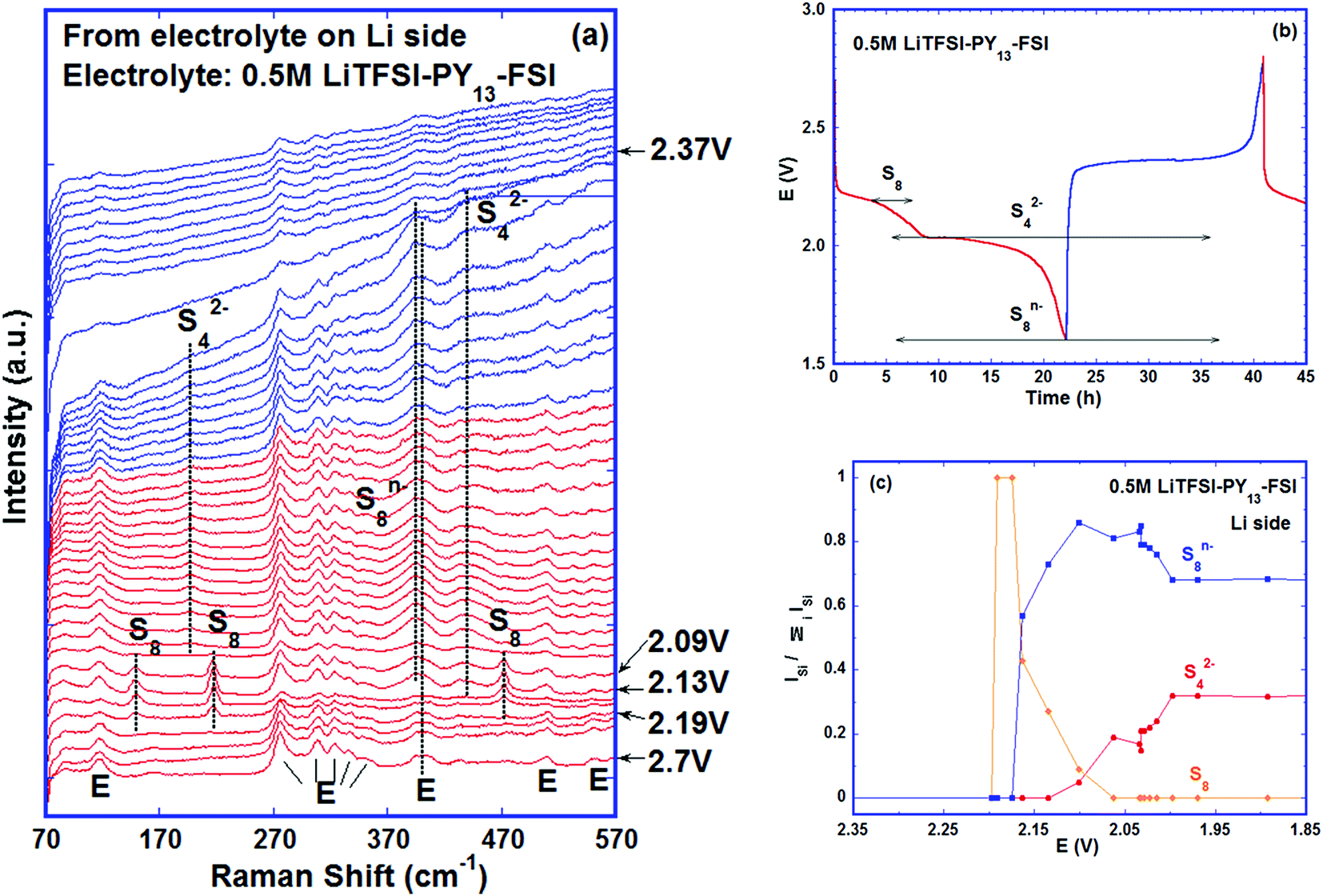 | ||
| Fig. 4 A Li–S cell with 0.5 M LiTFSI–PY13–FSI as the electrolyte cycled at a rate of C/48. (a) Evolution of Raman spectra collected from the electrolyte on the lithium side of the cell; E: electrolyte; (b) the poly-sulfide species detected via Raman spectroscopy with their corresponding potentials, red: discharge; blue: charge; (c) intensity ratios of poly-sulfides vs. potential. | ||
 | ||
| Fig. 5 Schematic of the reduction process combining the results related to the cathode and lithium metal side. | ||
Obviously at ∼2.20 V, the elemental sulfur is the main species at the cathode side and it is also detected at the same voltage near the lithium metal. During discharge, S8 is converted to S8n− at the cathode. On the lithium side, the amount of S8n− suddenly increases at 2.15 V which is caused by two factors: (i) reduction of S8 to S8n− in contact with lithium metal and (ii) the diffusion of S8n− from the positive electrode. On further discharge, the S8 was exhausted at ∼2.05 V on both sulfur and lithium sides. Approaching the end of the S8 reduction near the lithium metal surface, S42− was observed due to subsequent reduction of S8n− to smaller poly-sulfides. Disulfides are only detected at the positive electrode below 2.05 V while S42− is consumed. It is important to note that below 2.05 V the variation of the relative amounts of the species is small on the lithium metal side.
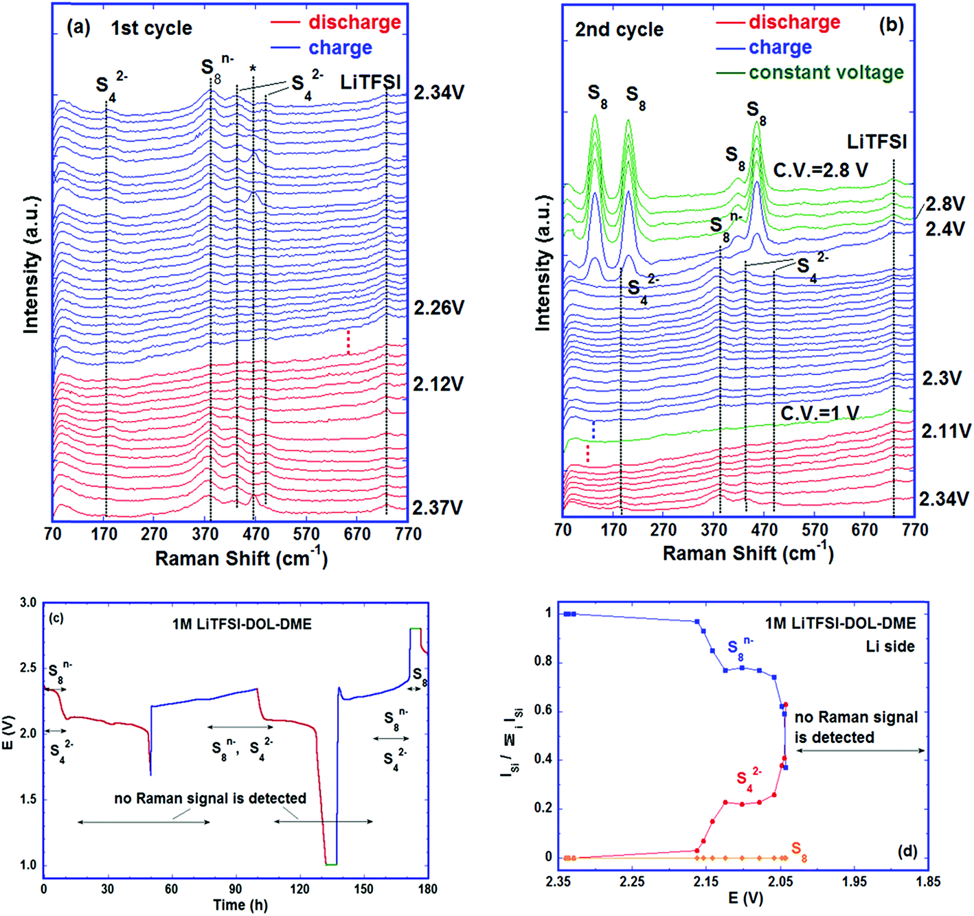 | ||
| Fig. 6 A Li–S cell with 1 M LiTFSI–DOL–DME as the electrolyte cycled at C/60. The Raman spectra were collected from the electrolyte on the lithium side. Evolution of Raman spectra during (a) first cycle; *:separator; (b) second cycle; dotted lines represent more spectra; (c) the poly-sulfide species detected via Raman and their corresponding potentials. Red: discharge; blue: charge; green: constant voltage; (d) relative intensities of polysulfides vs. potential. | ||
In order to verify whether other reduction products can be detected in the electrolyte at the end of discharge, the second cycle was discharged to 1 V and kept at this voltage for 5 hours before charge was started. Similar to the first cycle, no Raman bands were observed between the low voltage plateau (2.1 V) of the discharge step and the first half of the charge plateau (2.3 V). Subsequently, S42− and S8n− coexisted before the voltage reached ∼2.4 V. Starting at ∼2.4 V, the intensities of the S42− and S8n− bands declined quickly, accompanied by fast formation of S8, suggesting the electrochemical reactions:
| 2Li2S4 → Li2S8 + 2Li+ + 2e− | (EC-5) |
| Li2S8 → S8 + 2Li+ + 2e− | (EC-6) |
Only S8 was seen at the end of charge and its amount was almost unchanged during the 5 hour hold at 2.8 V, see Fig. 6b. The detection of elemental sulfur near the lithium metal at the end of charge (Fig. S6, ESI†) indicates that it plays an important role in lowering battery capacity and cyclability because (1) the sulfur can deposit on the lithium anode and change its surface morphology and conductivity; (2) the elemental sulfur corrodes the anode by reacting with lithium metal and forming thermodynamically preferred phase Li2S8;44 (3) the soluble Li2S8 formed reacts with lithium or disproportionates into other poly-sulfides and then reacts with lithium, which corrodes lithium further and forms resistive Li2S on the surface;49,50 (4) the soluble polysulfides formed enhance the shuttle reaction. All these effects increase the cell impedance and thus reduce the capacity and shorten the cycle life. The observation of elemental sulfur and polysulfides in the electrolyte besides lithium confirms most directly that the deterioration of the lithium anode and shuttle reactions are the important mechanisms for the capacity fade of the battery. The cycling curve and the polysulfide species detected in this cell are plotted in Fig. 6c and the variation of intensity ratios of the species versus potential is shown in Fig. 6d.
The poly-sulfide species detected in the two electrolytes near lithium metal are the same, i.e., S8n− and S42− due to the low donor number and low dielectric constant of both electrolytes,13,38,51 but they were observed at different stages of cycling indicating the differences in the kinetics of poly-sulfide formation and diffusion in different electrolytes (Fig. S7, ESI†). Examining Fig. 4 and 6, it is clear that for the cells containing DOL–DME, the reactions of S8 → S82− and S82− → S42− as well as the migration of S82− and S42− to the lithium side happened as soon as the cells were assembled and the S82− and S42− were observed before cycling began (though in Fig. 6d, the intensity ratio of S42− is 0 at 2.35 V, because at this moment, no S42− band at ∼200 cm−1 was seen, but other S42− bands were detected as shown in Fig. 6a). In contrast, in the cell using LiTFSI–PY13–FSI, no sulfur related species were observed until discharge to ∼2.20 V; while V < 2.20 V, the movement of S8 species to the lithium side was seen, followed by the ring opening and the breakup of the long chain. Comparing Fig. 4c and 6d, the intensity ratios of S8n− in both cells were similar at 2.1 V; but at 2.05 V, the intensity ratio of S8n− was close to its value at 2.1 V in the ionic liquid cell whereas it is greatly reduced in the ether-based electrolyte accompanied by a quick increase of S42−. This slow kinetics of poly-sulfide formation in the ionic liquid cell is mainly due to the higher viscosity and lower poly-sulfide solubility in it in comparison to DOL–DME,52,53 which is beneficial to minimise the loss of active material and reduce the shuttle reaction. But this advantage is overridden by the low ionic mobility in the ionic liquid owing to its high viscosity. Our cyclability tests confirmed this by showing that the cells using PY13–FSI have lower capacity and faster capacity fade (Fig. S8, ESI†) than those using DOL–DME.
4. In situ X-ray diffraction measurements
The phases formed during cycling were monitored by in situ XRD. Fig. 7a shows the plots of the cell potential as a function of time, and Fig. 7b shows the evolution of XRD spectra of a cell using 1 mol L−1 LiTFSI–DOL–DME as the electrolyte, with addition of 2 vol% LiNO3 to reduce the shuttling effect.33,54 The pristine cathode contained α-sulfur (PDF: 01-078-1888) having an orthorhombic crystal lattice with a space group Fddd (Fig. S2, ESI†). The discharge started at 2.43 V, and α-sulfur was undetectable at 2.34 V approaching the end of the high voltage plateau suggesting that the sulfur structure became non-crystalline quickly. A broad peak centred at 2θ ∼ 26.9° started to form in the second half of the low voltage plateau and grew thereafter; it reached the maximum when the cell was held at a constant voltage of 1.5 V. This broad peak is attributed to Li2S; its broadness indicated that the crystallinity of the phase was poor. The average crystal size estimated with the Scherrer formula was ∼10 nm. The Li2S peak was almost unchanged until the charge voltage reached ∼2.3 V at the middle of the charge plateau; it gradually diminished and completely vanished at ∼2.36 V. Only one small peak was evident at the end of the first charge, whereas more peaks were observed at the end of the second and third charge cycles. Although some peaks appeared at 24.02° and 35.02° it is uncertain whether β-sulfur (PDF: 04-007-2070) was formed at this moment considering that other high intensity peaks were not detected in the spectrum. The peaks formed at the end of the 3rd charge and the following constant voltage period were indexed to β-sulfur with a monoclinic structure (S.G. P21/c), which was also observed by Walus et al.15 The β-sulfur is reported to be stable at temperatures > 95 °C (ref. 55) whereas it is obtained in the Li–S cell at room temperature. It is possible that the nucleation of β-sulfur from the long chain poly-sulfides dissolved in the electrolyte is more energetically preferred than the α-phase; as a result, β-sulfur is formed first as a metastable phase, as schematically shown in Fig. 8. This phase identification is complementary to our Raman experimental results.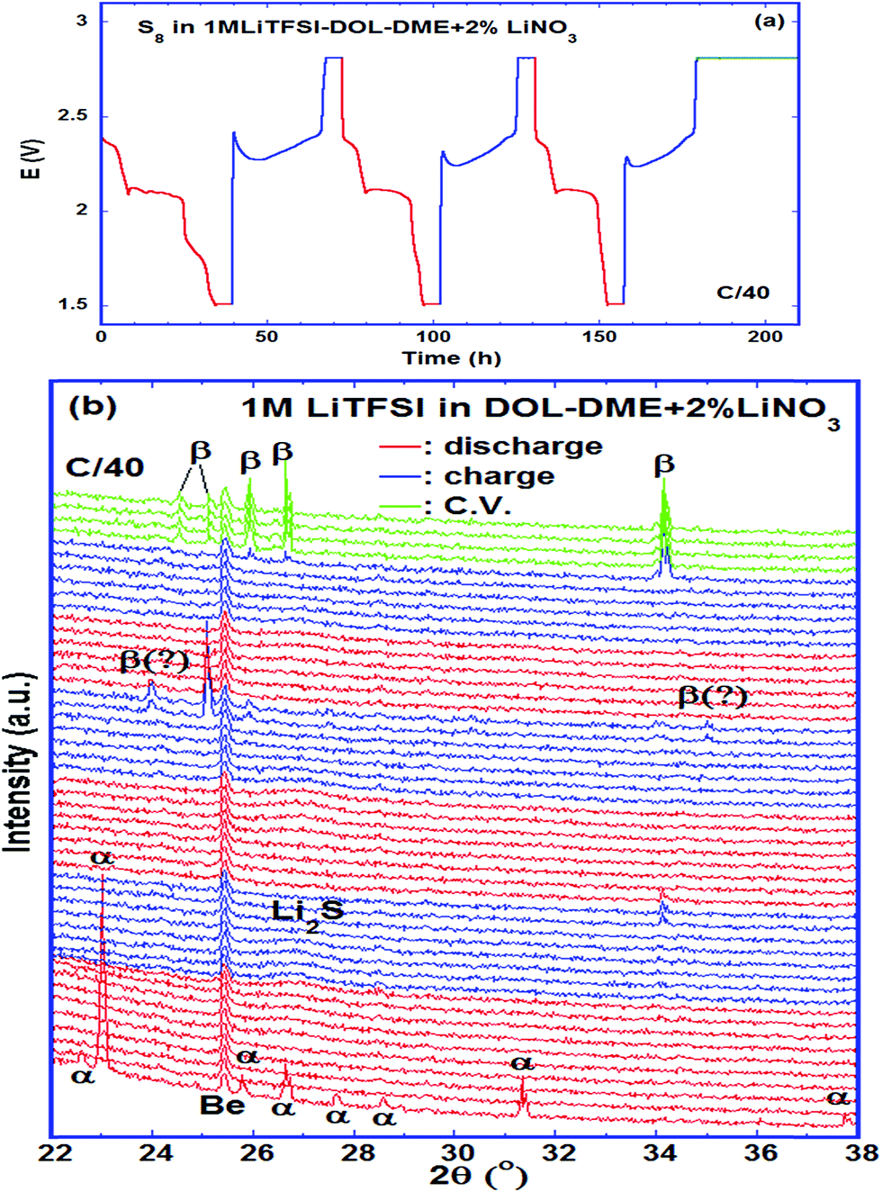 | ||
| Fig. 7 A Li–S cell using 1 M LiTFSI–DOL–DME–2% LiNO3 as the electrolyte cycled at a rate of C/40. (a) Discharge–charge curve; (b) evolution of XRD spectra showing the formation of β-sulfur at the end of charge. Red: discharge; blue: charge; green: constant voltage. | ||
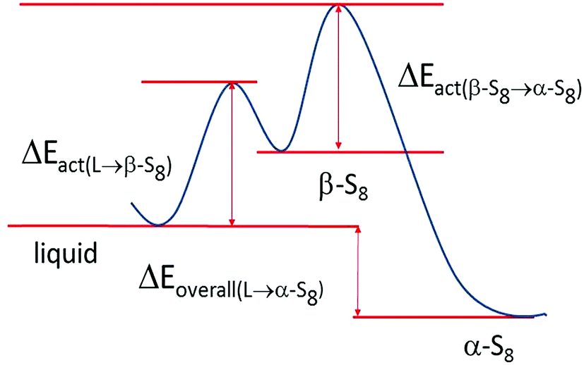 | ||
| Fig. 8 A schematic diagram illustrating the reaction energies in the formation of β and α sulfur. | ||
5. Conclusions
The poly-sulfide species formed at different voltages during galvanostatic cycling have been identified. For the cell using 0.5 mol L−1 LiTFSi–PY13–FSI electrolyte, the S8 ring and S8n− coexisted on the first reduction plateau, whereas S42−, S22−and S2− were formed on the second plateau at almost the same potential. At the end of discharge, S2− and other unknown species were observed, with the former as the end product of the reduction and the latter probably related to the disproportionation reaction. A discharge mechanism is proposed for the cell using the ionic liquid which provides fundamental information on the discharge process which is an important step for the amelioration of Li–S batteries. The evolution of polysulfide species during charge is the reverse process to discharge despite the differences of their corresponding potentials. The end product of charge is cycloocta S8 identified with a monoclinic structure via XRD. By examining the poly-sulfide species in the electrolyte phase near lithium in both PY13–FSI and DOL–DME, we found that the species in the two electrolytes are the same, but the kinetics of sulfur ring opening and breakup into short chain poly-sulfides are slower in 0.5 mol L−1 LiTFSI–PY13–FSI than in 1 mol L−1 LiTFSI–DOL–DME, which is beneficial for reducing the shuttling effect. On the other hand, the low mobility of polysulfides in the liquid electrolyte lowers the utilization of active sulfur in the battery, preventing the participation of soluble polysulfide in electrochemical reactions in the cathode and reducing the cyclability. The detection of S8 in the electrolyte near the lithium electrode confirms that the parasitic reactions on the Li metal anode involve the direct self-discharge reduction of elemental sulfur, as well as soluble polysulfide species, which are related to lithium corrosion and the loss of active material in the Li–S battery.Conflict of interest
The authors declare no competing financial interest.References
- N. Jayaprakash, J. Shen, S. S. Moganty, A. Corona and L. A. Archer, Angew. Chem., 2011, 123, 6026 CrossRef.
- R. Xu, J. Lu and K. Amine, Adv. Energy Mater., 2015, 5, 1500408 CrossRef.
- M. A. Pope and I. A. Aksay, Adv. Energy Mater., 2015, 5, 1500124 CrossRef.
- S. E. Cheon, K. S. Ko, J. H. Cho, S. W. Kim, E. Y. Chin and H. T. Kim, J. Electrochem. Soc., 2003, 150(6), A800 CrossRef CAS.
- C. Li, H. Zhang, L. Otaegui, G. Singh, M. Armand and L. M. Rodriguez-Martinez, J. Power Sources, 2016, 326, 1 CrossRef CAS.
- A. Manthiram, Y. Fu and Y. S. Su, Acc. Chem. Res., 2013, 46(5), 1125 CrossRef CAS PubMed.
- J. A. Dean, Lange's Handbook of Chemtry, McGRAW-HILL, New York, 15th edn, 1999 Search PubMed.
- P. P. R. M. L. Harks, C. B. Robledo, T. W. Verhallen, P. H. L. Notten and F. M. Mulder, Adv. Energy Mater., 2016, 1601635 Search PubMed.
- K. Zhang, L. Wang, Z. Hu, F. Cheng and J. Chen, Sci. Rep., 2014, 4, 6467 CrossRef CAS PubMed.
- D.-W. Wang, Q. Zeng, G. Zhou, L. Yin, F. Li, H.-M. Cheng, I. R. Gentle, G. Qing and M. Lu, J. Mater. Chem. A, 2013, 1, 9382 CAS.
- C. Barchasz, F. Molton, C. Duboc, J.-C. Leprêtre, S. Patoux and F. Alloin, Anal. Chem., 2012, 84, 3973 CrossRef CAS PubMed.
- Q. Wang, J. Zheng, E. Walter, H. Pan, D. Lv, P. Zuo, H. Chen, Z. D. Deng, B. Y. Liaw, X. Yu, X. Yang, J.-G. Zhang, J. Liu and J. Xiao, J. Electrochem. Soc., 2015, 162(3), A474 CrossRef CAS.
- Q. Zou and Y.-C. Lu, J. Phys. Chem. Lett., 2016, 7, 1518 CrossRef CAS PubMed.
- M. Cuisinier, C. Hart, M. Balasubramanian, A. Garsuch and L. F. Nazar, Adv. Energy Mater., 2015, 5, 1401801 CrossRef.
- S. Walus, C. Barchasz, R. Bouchet, J.-C. Leprêtre, J.-F. Colin, J.-F. Martin, E. Elkaïm, C. Baehtz and F. Alloin, Adv. Energy Mater., 2015, 5, 1500165 CrossRef.
- N. A. Cañas, S. Wolf, N. Wagner and K. A. Friedrich, J. Power Sources, 2013, 226, 313 CrossRef.
- A. Paolella, W. Zhu, H. Marceau, C.-S. Kim, Z. Feng, D. Liu, C. Gagnon, J. Trottier, A. Guerfi, P. Hovington, A. Vijh, G. P. Demopoulos, M. Armand and K. Zaghib, J. Power Sources, 2016, 325, 641 CrossRef CAS.
- J. Nelson, S. Misra, Y. Yang, A. Jackson, Y. Liu, H. Wang, H. Dai, J. C. Andrews, Y. Cui and M. F. Toney, J. Am. Chem. Soc., 2012, 134, 6337 CrossRef CAS PubMed.
- M. U. M. Patel, R. Demir-Cakan, M. Morcrette, J.-M. Tarascon, M. Gaberscek and R. Dominko, ChemSusChem, 2013, 6, 1177 CrossRef CAS PubMed.
- H. Marceau, C. S. Kim, A. Paolella, S. Ladouceur, M. Lagacé, M. Chaker, A. Vijh, A. Guerfi, C. M. Julien, A. Mauger, M. Armand, P. Hovington and K. Zaghib, J. Power Sources, 2016, 319, 247 CrossRef CAS.
- Y. Gorlin, A. Siebel, M. Piana, T. Huthwelker, H. Jha, G. Monsch, F. Kraus, H. A. Gasteiger and M. Tromp, J. Electrochem. Soc., 2015, 162, A1146 CrossRef CAS.
- M. Cuisinier, P.-E. Cabelguen, S. Evers, G. He, M. Kolbeck, A. Garsuch, T. Bolin, M. Balasubramanian and L. F. Nazar, J. Phys. Chem. Lett., 2013, 4, 3227 CrossRef CAS.
- K. H. Wujcik, T. A. Pascal, C. D. Pemmaraju, D. Devaux, W. C. Stolte, N. P. Balsara and D. Prendergast, Adv. Energy Mater., 2015, 5, 1500285 CrossRef.
- H. Yao, K. Yan, W. Li, G. Zheng, D. Kong, Z. W. Seh, V. K. Narasimhan, Z. Liang and Y. Cui, Energy Environ. Sci., 2014, 7, 3381 CAS.
- J.-T. Yeon, J.-Y. Jang, J.-G. Han, J. Cho, K. T. Lee and N.-S. Choi, J. Electrochem. Soc., 2012, 159, A1308 CrossRef CAS.
- M. Hagen, P. Schiffels, M. Hammer, S. Dorfler, J. Tubke, M. J. Hoffmann, H. Althues and S. Kaskel, J. Electrochem. Soc., 2013, 160, A1205 CrossRef CAS.
- J. Hannauer, J. Scheers, J. Fullenwarth, B. Fraisse, L. Stievano and P. Johansson, ChemPhysChem, 2015, 16, 2755 CrossRef CAS PubMed.
- H.-L. Wu, L. A. Huff and A. A. Gewirth, ACS Appl. Mater. Interfaces, 2015, 7, 1709 CAS.
- Y. Diao, K. Xie, S. Xiong and X. Hong, J. Electrochem. Soc., 2012, 159, A1816 CrossRef CAS.
- M. Wild, L. O'Neill, T. Zhang, R. Purkayastha, G. Minton, M. Marinescu and G. J. Offer, Energy Environ. Sci., 2015, 8, 3477 CAS.
- N. N. Greenwood, Spectroscopic Properties of Inorganic and Organometallic Compounds, The Chemical Society, Burlington House, London, 1975, vol. 8, p. 245 Search PubMed.
- G. Gautier and M. Debeau, Spectrochim. Acta, Part A, 1974, 30, 1193 CrossRef.
- S. S. Zhang, Electrochim. Acta, 2012, 70, 344 CrossRef CAS.
- L. Suo, Z. Fang, Y.-S. Hu and L. Chen, Chin. Phys. B, 2016, 25, 016101 CrossRef.
- J.-C. Lassègues, J. Grondin, C. Aupetit and P. Johansson, J. Phys. Chem. A, 2009, 113, 305 CrossRef PubMed.
- F. P. Daly and C. W. Brown, J. Phys. Chem., 1975, 79, 350 CrossRef CAS.
- F. P. Daly and C. W. Brown, J. Phys. Chem., 1973, 77, 1859 CrossRef CAS.
- Y. C. Lu, Q. He and H. A. Gasteiger, J. Phys. Chem. C, 2014, 118, 5733 CAS.
- G. J. Janz, J. R. Downey Jr, E. Roduner, G. J. Wasilczyk, J. W. Coutts and A. Eluard, Inorg. Chem., 1976, 15, 1759 CrossRef CAS.
- O. El Jaroudi, E. Picquenard, A. Demortier, J.-P. Lelieur and J. Corset, Inorg. Chem., 2000, 39, 2593 CrossRef CAS PubMed.
- O. El Jaroudi, E. Picquenard, A. Demortier, J.-P. Lelieur and J. Corse, Inorg. Chem., 1999, 38, 2394 CrossRef CAS.
- O. El Jaroudi, E. Picquenard, N. Gobeltz, A. Demortier and J. Corset, Inorg. Chem., 1999, 38, 2917 CrossRef CAS PubMed.
- K. Zhang, L. Wang, Z. Hu, F. Cheng and J. Chen, Sci. Rep., 4, 6467, DOI:10.1038/srep06467.
- R. S. Assary, L. A. Curtiss and J. S. Moore, J. Phys. Chem. C, 2014, 118, 11545 CAS.
- Z. Yuan, H.-J. Peng, T.-Z. Hou, J.-Q. Huang, C.-M. Chen, D.-W. Wang, X.-B. Cheng, F. Wei and Q. Zhang, Nano Lett., 2016, 16, 519 CrossRef CAS PubMed.
- Z. Černosek, J. Holubova, E. Černoskova and A. Ruzicka, J. Non-oxide Glasses, 2009, 1, 38 Search PubMed.
- G. Gautier and M. Debeau, Spectrochim. Acta, Part A, 1976, 32, 1007 CrossRef.
- L. Suo, O. Borodin, T. Gao, M. Olguin, J. Ho, X. Fan, C. Luo, C. Wang and K. Xu, Science, 2015, 350, 938 CrossRef CAS PubMed.
- J. Zheng, D. Lv, M. Gu, C. Wang, J.-G. Zhang, J. Liu and J. Xiao, J. Electrochem. Soc., 2013, 160, A2288 CrossRef CAS.
- H. Kim, J. T. Lee and G. Yushin, J. Power Sources, 2013, 226, 256 CrossRef CAS.
- E. Izgorodina, M. Forsyth and D. Macfariane, Phys. Chem. Chem. Phys., 2009, 11(14), 2452 RSC.
- Q. Zhou, W. A. Henderson, G. B. Appetecchi, M. Montanino and S. Passerini, J. Phys. Chem. B, 2008, 112, 13577 CrossRef CAS PubMed.
- L. Suo, Y.-S. Hu, H. Li, M. Armand and L. Chen, Nat. Commun., 2013, 4, 1481 CrossRef PubMed.
- X. Liang, Z. Wen, Y. Liu, M. Wu, J. Jin, H. Zhang and X. Wu, J. Power Sources, 2011, 196, 9839 CrossRef CAS.
- B. Meyer, Chem. Rev., 1976, 76, 367 CrossRef CAS.
Footnote |
| † Electronic supplementary information (ESI) available. See DOI: 10.1039/c6se00104a |
| This journal is © The Royal Society of Chemistry 2017 |