CeO2@C derived from benzene carboxylate bridged metal–organic frameworks: ligand induced morphology evolution and influence on the electrochemical properties as a lithium-ion battery anode†
Received
27th October 2016
, Accepted 29th December 2016
First published on 12th January 2017
Abstract
We report herein a facile metal–organic framework (MOF) derived route for the synthesis of carbon embedded CeO2 (CeO2@C) with a pre-designed shape-specific morphology by varying the organic linker and by using PVP as the structure directing agent. It is found that the general morphological features of the parent MOF are mimicked by the derived oxide. Four different linkers have been used to prepare CeO2@C particles with three different shapes – spherical, bar-shaped and thin plate-like. A probable formation mechanism is discussed based on metal–ligand coordination. Influence of the morphology on the electrochemical properties as a lithium-ion battery (LIB) anode has been studied in coin cells vs. Li/Li+. The spherically shaped CeO2@C-14 shows a superior performance with a maximum specific capacity of 715 mA h g−1 at 0.05 mA cm−2, good rate performance (413 mA h g−1 at 0.5 mA cm−2) and cycling stability (∼94% capacity retention after 100 cycles). The present results demonstrate that the major limitations of metal oxide anodes – volume expansion during lithiation/delithiation, rate performance and capacity fading upon cycling – could be overcome to a great extent by adopting the two-way approach of morphology design through the MOF route and in situ embedded carbon matrix.
Introduction
It is now well recognized that for continued success of lithium-ion batteries (LIBs), appropriate anode materials must be found that can sustain high rate capability in order to substitute orthodox carbonaceous anodes which suffer from low specific capacity (372 mA h g−1 theoretical), poor Li+ intercalation kinetics and safety concerns.1 Metal oxide anodes, particularly those involving a conversion-type mechanism generally offer high specific capacity.2 Thus, widespread research has been conducted on various metal oxides such as, V2O5,3–5 Mn2O3,6,7 Mn3O4,8–10 Fe2O3,11–13 Fe3O4,14–16 CoO,17–20 Co3O4,21–23 NiO,24–26 CuO,27–29 SnO2,30–32etc. Cerium oxide (CeO2) is one of the most promising rare earth oxides offering multiple exciting properties including oxygen storage capacity, high thermal stability, good optical properties and ionic diffusivity.33–35 Thus, it has found diverse applications in superconductors, solid oxide fuel cells, gas storage etc.36–41 In recent years, it is also being viewed as a potential candidate for the lithium-ion battery (LIB) anode exploiting the presence of a fast mutually expedient transition of Ce(III) and Ce(IV) within a fluorite structure. As the electrochemical process does not lead to complete reduction to the metallic state (Ce0), the associated volumetric change is relatively low (∼17%) with a radial expansion of only ∼5.4%.42 However, despite the favorable attributes, only a handful of studies are devoted, till now, to explore the LIB properties of CeO2. Zhou et al.43,44 have reported a discharge capacity of 550 mA h g−1 for spherical CeO2 particles with ∼4% fading after 50 cycles. To improve the electrical conductivity, carbon based composite anodes have been investigated. A CeO2–graphene nano-composite anode shows a high charge capacity of 991 mA h g−1 at 50 mA g−1, but the columbic efficiency is low (67%) and due to continuous fading the capacity drops down to ∼605 mA h g−1 after 100 cycles.45 Guo et al. have developed a graphene/CeO2/CMK-3 based composite material and observed a steady capacity of ∼550 mA h g−1 after 100 cycles.46 Recently, Wu et al. showed that CeO2@C core–shell spheres exhibited a high discharge capacity of 863 mA h g−1 but, due to fading a capacity of only 355 mA h g−1 could be obtained after 50 cycles.47 Micro/nano core–shell sphere of CeO2, developed from a chelating precursor, also shows a good discharge capacity of ∼547 mA h g−1 after 300 cycles.48 Pang et al. demonstrated that the specific capacity of the brick-like CeO2 nanostructure shows a better capacity (460 mA h g−1 with good stability till 100 cycles) than plate-shaped CeO2 (290 mA h g−1).49 Liu et al. have developed rhombus and quasi-rhombus microplates of ceria and observed better performance with the rhombus morphology (a discharge capacity of 374.4 mA h g−1 after 50 cycles).50 Cheng et al. demonstrated a discharge capacity of 319.5 mA h g−1 from a prism-like CeO2 microrods after 100 cycles at a current density of 0.2 mA cm−2.51 Liu et al. developed micro/nano dumbbell-shaped CeO2,52 and core–shell CeO2 micro/nanospheres,53 which delivers discharge capacities of 590 and 327 mA h g−1 respectively, after 100 cycles at a current density of 0.2 mA cm−2. From the above, it transpires that not only the presence of carbon, but also the morphology and microstructure play a pronounced role in improving the electrochemical performance. It is found that by designing hierarchical porous nanostructures or core–shell nanomaterials, the large lattice volume changes in metal oxides during lithiation/de-lithiation could be mitigated.54–56 In this respect, metal organic frameworks (MOFs), which are constructed by using clusters of metal ions and organic linkers, offer vast opportunities to obtain nanomaterials thereof with unique structural features. A variation in coordinating linkers, by virtue of their different coordination ability with the metal center, would result in different types of morphological features. This would provide us with an opportunity to pre-design the morphology of the derived CeO2 which could be inherited from the respective parent MOF. A number of studies including some excellent reviews are available on the synthesis of metal oxides from MOFs.57–60 However, until now, no systematic study is available on how the symmetry of different linkers would affect the final morphology of an MOF where the metal centre remains the same. Recently, we have successfully synthesized nanostructured CeO2 with a unique brick-upon-tile morphological pattern by exo-templating of the Ce(1,3,5-BTC)(H2O)6 [1,3,5-BTC = 1,3,5-benzene tricarboxylate] metal–organic framework.61 In the present study, we have synthesized a series of MOF in high yields using Ce as the metal centre but with four different BTC ligands namely, 1,4-benzenedicarboxylic acid (1,4-H2BDC), 1,2,4-benzenetricarboxylic acid (1,2,4-H3BTC), 1,3,5-benzenetricarboxylic acid (1,3,5-H3BTC) and 1,2,4,5-benzenetetracarboxylic acid (1,2,4,5-H4BTEC) as organic linkers in H2O/ethanol medium using poly(vinylpyrrolidone) (PVP) as a stabilizing as well as a structure-directing agent. Further, to overcome the low conductivity issue, the MOFs are heat treated in an Ar atmosphere to obtain CeO2 embedded in a carbon matrix, CeO2@C through carbonization of the organic moieties. The MOF-derived CeO2@C materials with different morphology have been tested as the LIB anode and their relative performances are compared. It is found that CeO2@C-14, with a spherical morphology which was derived from the Ce-1,4-BDC MOF, shows a commendable performance exhibiting a reversible capacity of 715 mA h g−1 after 10th cycle and 673 mA h g−1 at 0.05 mA cm−2 after 100th cycle with a fading rate of 0.06% per cycle and a good rate performance (715, 674, 551 and 413 mA h g−1 at current densities of 0.05, 0.1, 0.2 and 0.5 mA cm−2 respectively).
Experimental
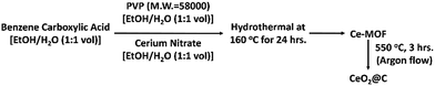
Synthesis of Ce-1,4-BDC/1,2,4-BTC/1,3,5-BTC/1,2,4,5-BTEC MOFs
The MOFs were synthesized by a simple solvothermal method. All four MOFs (Ce-1,4-BDC MOF, Ce-1,2,4-BTC MOF, Ce-1,3,5-BTC MOF and Ce-1,2,4,5-BTEC MOF) have been synthesized via the same experimental procedure by varying only the organic linkers. In a typical synthesis, Ce(NO3)3·6H2O (5 mmol, Acros Organics 99.5%), the organic linker [1,4-H2BDC (5 mmol, Acros Organics, 98%) or 1,2,4-H3BTC (5 mmol, Acros Organics, 98%) or 1,3,5-H3BTC (5 mmol, Acros Organics, 98%) or 1,2,4,5-H4BTEC (5 mmol, Acros Organics, 98%)], and PVP (MW = 58![[thin space (1/6-em)]](https://www.rsc.org/images/entities/char_2009.gif) 000, 0.05 mmol, Acros Organics) were dissolved individually in H2O–ethanol solution (60 mL, v/v = 1:1) under magnetic stirring. First, PVP solution was added dropwise to the organic linker solution with continuous stirring. Next, the cerium nitrate solution was added in a dropwise manner and the stirring was continued for another 10 min. The solution was then transferred to a 100 mL Teflon-lined stainless-steel autoclave, heated at 160 °C for 24 h and cooled to room temperature. The resulting powder was separated by centrifugation at 10000 rpm for 10 min, washed with ethanol several times and dried in a vacuum oven at 60 °C.
000, 0.05 mmol, Acros Organics) were dissolved individually in H2O–ethanol solution (60 mL, v/v = 1:1) under magnetic stirring. First, PVP solution was added dropwise to the organic linker solution with continuous stirring. Next, the cerium nitrate solution was added in a dropwise manner and the stirring was continued for another 10 min. The solution was then transferred to a 100 mL Teflon-lined stainless-steel autoclave, heated at 160 °C for 24 h and cooled to room temperature. The resulting powder was separated by centrifugation at 10000 rpm for 10 min, washed with ethanol several times and dried in a vacuum oven at 60 °C.
Synthesis of MOF derived CeO2@C
CeO2@C was synthesized by heat treatment of the respective MOF in an Ar atmosphere inside a tube furnace at 550 °C for 3 h with a heating rate of 5 °C per min. The obtained CeO2 powders are named CeO2@C-14, CeO2@C-124, CeO2@C-135 and CeO2@C-1245 (derived from Ce-1,4-BDC MOF, Ce-1,2,4-BTC MOF, Ce-1,3,5-BTC MOF and Ce-1,2,4,5-BTEC MOF respectively).
A schematic representation of the overall synthesis process is shown in Scheme 1 (also, see Scheme S1, ESI†).
 |
| | Scheme 1 Stepwise synthesis of CeO2@C. | |
Physical characterization
Formation of the MOFs and phase purity of the oxides derived thereof have been checked by X-ray diffraction analysis. Diffractograms were recorded in the 2θ range 8–50° (for MOFs) and 20–80° (for CeO2@C) at a scanning rate of 2° min−1 by using an X-ray diffractometer (Philips X'Pert, The Netherlands) with a Cu-Kα radiation at 40 KV and 40 mA. The microstructure and morphology were examined by using a field emission scanning electron microscope (ZEISS Supra 35, Germany). A transmission electron microscope (TEM), Tecnai G2 30ST (FEI) with an accelerating voltage of 300 kV was used to obtain the TEM, high resolution TEM images (HRTEM) and selected area electron diffraction (SAED) pattern. To recognize the characteristic bands, Fourier transform infrared spectroscopy (FTIR) was performed in the wave number range from 4000 to 450 cm−1 using a BOMEN infrared spectrophotometer in transmission mode. Thermogravimetric analysis (TGA) of the powder samples were carried out under an argon flow at a heating rate of 10 oC min−1 using a Simultaneous Thermal Analyzer (STA 449F, Netzsch, Germany). Raman signals were obtained from powder samples using an Ar+ ion laser at 514.5 nm wavelength with 50 mW power. A 20× objective lens was used for the 10–12 μm laser spot size with 20 seconds of Raman signal acquisitions for 3 times each (model STR500, Cornes technologies, USA). Brunauer–Emmett–Teller (BET) surface area measurements were carried out by N2 gas adsorption at 77.3 K using a Quantachrome (USA) Autosorb surface analyser. The pore size distribution was calculated from the sorption isotherm by the Barrett–Joyner–Halenda (BJH) method. X-ray photoelectron spectroscopy (XPS) (model: PHI 5000 VersaProbe-II) measurement was performed with the electrode at the fully discharged state (at 0.01 V) to understand the chemical state of Ce.
Electrochemical characterization
Working electrodes were fabricated by the standard slurry casting method. The slurry was made by intimately mixing CeO2 powder (active material), Super-P (conducting agent) and polyvinylidene fluoride (binder) in a weight ratio of 70:20:10 in n-methyl pyrrolidinone (solvent). A thick film (green thickness ∼ 100 μm) was prepared by coating the slurry onto a copper foil of thickness 15 μm. After drying at 110 °C for 5 h in a vacuum oven and pressing at 4.0 ton per inch2, the film was cut into circular disk electrodes of area 1.76 cm2. The active mass of the electrodes were ∼1.8 mg cm−2. Electrochemical properties were evaluated by fabricating 2032 type coin cells in an argon filled glovebox (M'BRAUN, Germany) where the moisture and oxygen levels were kept at <0.5 ppm. Li metal was used as the counter as well as the reference electrode, Celgard 2300 as the separator and 1.0 M LiPF6 in EC:DMC (1:2 vol%) as the electrolyte. Cyclic voltammetry (CV) was carried out in the potential window of 0.01–3.0 V by using a galvanostat-potentiostat (PGSTAT302N, Autolab, The Netherlands). Electrochemical impedance spectroscopy (EIS) experiments were also performed by using the same galvanostat-potentiostat in the frequency range of 100 kHz to 0.1 Hz. Galvanostatic charge–discharge measurements were carried out in the same potential window by using an automatic battery tester (BT2000, Arbin, USA).
Results and discussion
Physical characterization
It is known that the carboxylate functional groups act as the nucleation sites for the MOF crystal growth.30,62 Formation of respective MOF has been checked by XRD and FTIR studies. Fig. 1a–d show the X-ray diffractograms of the synthesized MOFs. Observation of sharp diffraction peaks in each case indicates a good crystallinity.
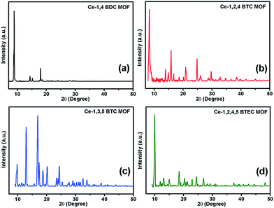 |
| | Fig. 1 X-ray diffractograms of the synthesized MOFs (a) Ce-1,4 BDC MOF, (b) Ce-1,2,4 BTC MOF, (c) Ce-1,3,5 BTC MOF, and (d) Ce-1,2,4,5 BTEC. | |
The observed diffraction peaks of Ce-1,4-BDC MOF, shown in Fig. 1a, are in good agreement with the reported XRD data of the Ce2(bdc)6·(H2O)4 MOF.63 Similarly, the diffractograms observed for the Ce-1,3,5-BTC MOF (Fig. 1b) and Ce-1,2,4,5-BTEC MOF (Fig. 1d) correspond to the reported XRD data of the Ce(1,3,5-BTC)(H2O)6 MOF64 and [Ce(H2btec)1/2(btec)1/2(H2O)]n MOF,65 respectively. Though there is no previous report of the Ce-1,2,4-BTC MOF, the observed X-ray diffractogram (Fig. 1c) closely resembles that of the Gd(1,2,4-BTC)(H2O)3·H2O MOF of the lanthanide MOF family.66 Further evidence for the coordination of carboxylate ligands with Ce can be obtained from FTIR. In the FTIR spectra, it is found that the characteristic bands (1686–1720 cm−1) of the non-ionised carboxylic groups of the linkers have disappeared while some new bands appear in the wavenumber region of 1612–1531 cm−1 (Fig. S1, ESI†). This observation proves that the cerium ions have been coordinated with the carboxylate ligands successfully to form the MOFs.62,67
Fig. 2 shows the X-ray diffractograms of the resulting CeO2@C, derived from different MOFs. The observed diffraction peaks could be indexed to (111), (200), (220), (311), (222), (400), (331) and (420) planes conforming to a cubic fluorite structure of the ceria phase with space group Fm3m. A somewhat broadened nature of the diffraction peaks originates from a low crystallite size and the presence of lattice strain. The obtained lattice parameter for each of the CeO2@C is also in good agreement with JCPDS data (file number 01-075-0390). The full width at half maximum (FWHM) values, average crystallite size and lattice strain for each of the CeO2@C are listed in Table S1, ESI.† The average crystallite size has been found to be in the range of 3.3–6.2 nm. These results suggest that difference in the carboxylate linker in the MOF does not significantly affect the crystal structure of the resulting CeO2. As the parent MOFs were heat-treated in an argon atmosphere (constant argon flow), the derived oxides contain carbon, generated in situ from the organic moiety. Thermogravimetric analyses (TGA) indicate the presence of 26.8, 20.9, 7.9 and 28.3 wt% of carbon in CeO2@C-14, CeO2@C-124, CeO2@C-135 and CeO2@C-1245 respectively (Fig. S2, ESI†).
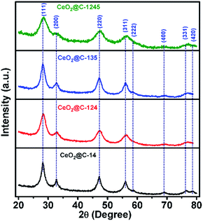 |
| | Fig. 2 X-ray diffractograms of CeO2@C (CeO2@C-14, CeO2@C-124, CeO2@C-135 and CeO2@C-1245) derived from the corresponding MOF. | |
Raman spectroscopy is an excellent tool for characterization of carbon containing materials. Therefore, Raman spectra of the synthesized CeO2@C have been recorded in the range 200–2000 cm−1 and are shown in Fig. 3 and also in Fig. S3 and S4, ESI.† CeO2 is characterised by observation of a typical band at ∼460 cm−1 corresponding to the F2g symmetry.61,68 On the other hand, the characteristic D-band (disordered) and G-band (graphitic) of carbon appear at ∼1350 and ∼1580 cm−1 respectively.69 Interestingly, CeO2@C-124 and CeO2@C-135 show sharp peak at ∼458 cm−1 and relatively weaker peaks at ∼1350 and 1580 cm−1. On the other hand, CeO2@C-14 and CeO2@C-1245 show very weak peak at ∼458 cm−1 and relatively stronger peaks at ∼1350 and 1580 cm−1 which may be due to the deep embedment of CeO2 crystallites in the carbon matrix. From the peak intensity ratio of D and G bands, the nanographite size has been calculated70 and tabulated in Table S2, ESI† along with other Raman spectra information. The nanographite crystal size is found to increase in the order: CeO2@C-135 < CeO2@C-1245 < CeO2@C-124 < CeO2@C-14. Further, it can be seen that all the Raman peaks are shifted from their theoretical positions (Table S2, ESI†). The CeO2 peaks are downshifted indicating the presence of tensile stress in the lattice, which revalidate the XRD results. On the other hand, the nanographite peaks are upshifted due to compressive stress present in the lattice.
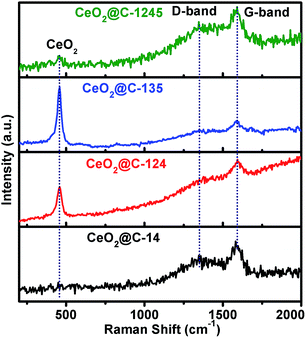 |
| | Fig. 3 Raman spectra of CeO2@C (CeO2@C-14, CeO2@C-124, CeO2@C-135 and CeO2@C-1245) in the range 200–2000 cm−1. | |
Morphology and microstructural features of the synthesized MOFs and the derived oxides have been examined by FESEM and TEM. Fig. 4a–h show the FESEM images of Ce-MOFs and corresponding CeO2@C. It is observed that the general morphological features of the parent MOF are mimicked by the derived oxide. However, depending on the ligand used, the morphology of the MOF varies. Ce-1,4-BDC MOF and Ce-1,2,4-BTC MOF are formed as spherical particles. The corresponding oxides, CeO2@C-14 and CeO2@C-124, are also spherical with diameters of 0.7–1.5 μm and 8–15 μm respectively (Fig. 4a–d).
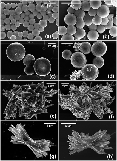 |
| | Fig. 4 FESEM micrographs of the synthesized benzene carboxylate MOFs and corresponding CeO2@C derived thereof: (a and b) Ce-1,4-BDC & CeO2@C-14 (c and d) Ce-1,2,4-BTC & CeO2@C-124 (e and f) Ce-1,3,5-BTC & CeO2@C-135 and (g and h) Ce-1,2,4,5-BTEC & CeO2@C-1245. | |
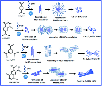
On the other hand, the Ce-1,3,5-BTC MOF shows a randomly orientated bar-shaped morphology with sharp edges. The dimensions of the bars in the derived CeO2@C-135 are 2–10 μm in length and 0.2–0.6 μm in diameter (Fig. 4e and f). In the case of Ce-1,2,4,5-BTEC MOF and CeO2@C-1245, the morphology can be described as twisted bundles of thick plate shaped particles with uneven edges (Fig. 4g and h). The variation in the morphology of different MOFs results from the varying metal–ligand coordination: the molecular structure of the carboxylic acid ligands and possible metal–ligand coordination for each of the carboxylate precursor are shown in Fig. S5 and S6, ESI.† Based on this, a probable formation mechanism of cerium based MOFs is presented in Scheme 2. Initially, heterogeneous nucleation and stepwise growth of metal–ligand networks occur under solvothermal conditions.71 BTC, BTEC or BDC ligands bridge with the Ce3+ ions through the oxygen atoms of the -COO- in the aromatic ring to form 1D ribbon-like molecular motifs due to the steric alignment of the carboxylate groups having flexible coordination. Then, the next ligand molecule coordinates with this Ce containing as-formed structure along the same direction. This coordination-induced assembly process went on until the weakening of reactants in the solution resulting in the formation of well-dispersed nanorods. Here, the organic ligands not only act as the reactant but also may act as the possible crystal face inhibitor in the formation process of nanorods. This phenomenon supports the formation of oriented nucleation leading to anisotropic growth of the nanorods. The anisotropic growth process could also be guided by the polar solvent: the final products, being insoluble in the polar solvents, would have minimum involvement with the solvent, which actually helps in 1D self-assembly through molecular stacking interactions.72 Interpenetration of these metal–ligand networks leads to the formation of a 3D framework which in turn, reorganise themselves into bar shaped (Ce-1,4-BDC & Ce-1,3,5-BTC) or plate shaped (Ce-1,2,4-BTC & Ce-1,3,4,5-BTEC) morphologies with different dimensions depending upon the organic linkers used. Similar to the present observations, Rieter et al. have reported that for Gd MOFs (Gd-1,4-BDC and Gd-1,2,4-BTC), the usual tendency of the 1,4-BDC ligand is to form nanorods/nanobars whereas 1,2,4-BTC ligands lead to nanoplates as the basic morphology.66 In the present study, PVP plays a dual role as a stabilising agent during the metal–ligand co-ordination as well as a structure-directing reagent by regulating the subsequent growth and assembly of the unit structures (bars and plates) through the bundle formation.73 In the case of Ce-1,4-BDC, due to the shorter length of the nanobars, the assembled bundles take a spherical shape. Similarly, due to the smaller dimensions, the nanoplates of Ce-1,2,4-BTC are also assembled in a pseudo-spherical morphology (Scheme 2 and Fig. S7a, ESI†). Jin et al. showed that in the absence of PVP, 1,4-H2BDC bridged Gd(1,4-BDC)1.5(H2O)2 forms a spindle-like shape instantly before miming the well-dispersed straw-like or bar-shaped morphology.73 On the other hand, the structural units of Ce-1,3,5-BTC and Ce-1,2,4,5-BTEC assemble themselves by their edges due to their relatively bigger dimension of the macrobars and macroplates (Scheme 2, Fig. S7b and c, ESI†).
 |
| | Scheme 2 Formation mechanism of Ce-1,4-BDC, Ce-1,2,4-BTC, Ce-1,3,5-BTC and Ce-1,2,4,5-BTEC MOF precursors. | |
TEM, HRTEM and SAED patterns of the MOF derived CeO2@C are shown in Fig. 5. The TEM image of CeO2@C-14 reveals a double shell spherical architecture (Fig. 5a) whereas, CeO2@C-124 shows a pseudo-spherical morphology with relatively bigger geometrical dimensions (Fig. 5b). On the other hand, bar shaped and plate-like morphologies have been observed for CeO2@C-135 and CeO2@C-1245 respectively (Fig. 5c and d), corroborating the observations in FESEM. The appearance of clear lattice fringes in HRTEM (Fig. 5e–h) indicates good crystallinity of the MOF-derived CeO2@C; the observed spacing of 0.27 and 0.32 nm correspond to the (200) and (111) planes of cubic CeO2. Further, the observation of spots arranged in circular rings in the selected area diffraction (SAED) patterns confirms the polycrystalline nature of the synthesized CeO2@C (Fig. 5i–l). N2 adsorption–desorption isotherms and corresponding pore size distributions of the MOF-derived oxides are shown in Fig. S8, ESI.† For all the cases, the isotherms are convex in nature up to P/P0 = 1.0, which is typical for type III isotherms. A discrete hysteresis loop starting from P/P0 = 0.45 reveals a porous nature and indicates the presence of interparticle as well as structural pores. The BET surface area values are calculated to be 159, 63, 73 and 39 m2 g−1 respectively for CeO2@C-14, CeO2@C-124, CeO2@C-135 and CeO2@C-1245.
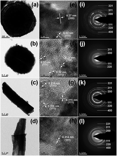 |
| | Fig. 5 TEM, HRTEM and SAED patterns of (a–c) CeO2@C-14, (d–f) CeO2@C-124, (g–i) CeO2@C-135 and (j–l) CeO2@C-1245. | |
Electrochemical characterization
Electrochemical properties of all the MOF-derived CeO2@C samples namely, CeO2@C-14, CeO2@C-124, CeO2@C-135 and CeO2@C-1245 have been investigated by fabricating coin cells vs. Li/Li+. At first, to understand the redox processes, cyclic voltammetry (CV) measurements were conducted and the results are shown in Fig. 6a–d.
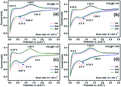 |
| | Fig. 6 Cyclic voltammetry (CV) plots of (a) CeO2@C-14, (b) CeO2@C-124, (c) CeO2@C-135 and (d) CeO2@C-1245. | |
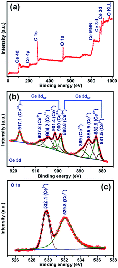
The CVs were recorded for three consecutive cycles at a scan rate of 0.1 mV s−1 in the potential window of 0.01–3.0 V vs. Li/Li+. The nature of CVs in all cases is similar: a broad cathodic peak at ∼0.7 V and two broad anodic peaks centered around 0.15–0.21 V and around 1.23–1.26 V. The peak at ∼0.7 V followed by a sloppy nature up to 0.01 V can be attributed to the reductive transformation of CeO2 to Ce2O3, lithiation in the carbon matrix and also to the formation of an SEI layer in the first scan.42 It is observed that the extent of the sloppy region to 0.01 V varies with the amount of embedded carbon present in the material: being a minimum for CeO2@C-135 (7.9 wt% of C, Fig. S2, ESI†) and maximum for CeO2@C-1245 (28 wt% of C, Fig. S2, ESI†). Therefore, the first anodic peak at ∼0.15–0.21 can be assigned to the de-lithiation from the carbon matrix. On the other hand, the prominent second anodic peak at ∼1.23–1.26 V occurs due to the oxidation reaction, Ce2O3 → CeO2. To confirm the conversion reaction, ex situ XPS studies were carried out on the CeO2@C-135 electrode after discharging (0.01 V). Fig. 7a shows the survey scan indicating the presence of C and O along with Ce. As shown in Fig. 7b, a number of peaks could be observed in the high resolution Ce 3d spectrum. Ce 3d core-level photoemission is very sensitive to the local valence revealing the oxidation state. The Ce 3d region has well separated spin–orbit components and each spin–orbit component is further split by multiplet splitting. The six characteristic components of CeO2 are clearly visible: three Ce 3d3/2 peaks at 917.1, 907.8 & 901.4 and three Ce 3d5/2 peaks at 898.8, 889.0 & 882.9 eV. On the other hand, the characteristic components of Ce2O3 could also be clearly discerned: two Ce 3d3/2 peaks at 904.2 & 900.0 and two Ce 3d5/2 peaks at 885.9 & 881.5 eV respectively. The presence of a peak at 917.1 eV indicates the existence of Ce4+. On the other hand, appearance of a shoulder at 881.5 eV is a signature of Ce3+. These results indicate the co-existence of Ce3+ and Ce4+ suggesting transformation of CeO2 to Ce2O3 during discharge. The presence of Ce4+ could be due to incomplete reduction during the first discharge. Further, the core-level O 1s spectrum clearly suggests the transformation of CeO2 into Ce2O3 by showing a shift of the O 1s level from 529.8 eV (CeO2) to a higher binding energy of 532.1 eV (Ce2O3) (Fig. 7b).74–78 These results are also in accordance with the observations of Su et al.42 where in situ TEM studies reveal a reversible transformation between fluorite CeO2 and cubic Ce2O3 during the electrochemical process. Thus, the electrochemical reactions can be represented as
| | | 2CeO2 + 2Li+ + 2e ↔ Ce2O3 + Li2O | (1) |
 |
| | Fig. 7 XPS spectra of CeO2@C-135 after discharging up to 0.01 V: (a) survey scan (b) Ce 3d and (c) O 1s. | |
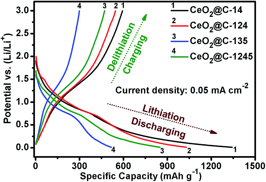
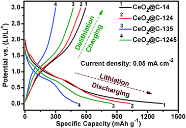
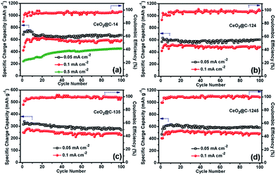
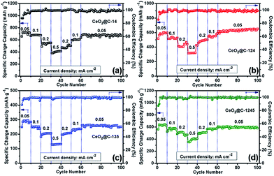
Fig. 8 represents the galvanostatic discharge–charge (GCD) profiles for the initial formation cycle for CeO2@C in the potential window of 0.01–3.0 V at a current density of 0.05 mA cm−2. Initial discharge/charge capacities of 1344/596 mA h g−1, 1032/546 mA h g−1, 517/301 mA h g−1 and 850/470 mA h g−1 have been found for CeO2@C-14, CeO2@C-124, CeO2@C-135 and CeO2@C-1245, respectively with first cycle coulombic efficiency (%) [(charge capacity/discharge capacity) × 100] of 44.3, 52.9, 58.2 and 55.3%. The somewhat low coulombic efficiency is common for transition metal oxide anodes and can be accounted for side reactions with the non-aqueous electrolyte as well as the formation of a solid electrolyte interface (SEI) layer on the electroactive materials.79,80 Interestingly, the bar-shaped or plate-like morphology of the particles (CeO2@C-135 and CeO2@C-1245) leads to a marginally better coulombic efficiency than the spherical morphology (CeO2@C-14, CeO2@C-124). On the other hand, the obtained charge capacities are higher for the spherically shaped particles than for bar shaped or plate-like particles. In order to check the cycling performance at different current densities, the CeO2@C cells have been tested for 100 continuous cycles at current densities between 0.05 and 0.5 mA cm−2 and the results are shown in Fig. 9a–d.
 |
| | Fig. 8 Initial discharge–charge profiles of CeO2@C-14, CeO2@C-124, CeO2@C-135 and CeO2@C-1245. | |
 |
| | Fig. 9 Electrochemical cycling performance of (a) CeO2@C-14, (b) CeO2@C-124, (c) CeO2@C-135 and (d) CeO2@C-1245 at current densities of 0.05, 0.1 and 0.5 (CeO2@C-14) mA cm−1. | |
In all cases, there is an increasing tendency for the first 5–10 cycles. This behavior can be related to the wetting and gradual activation of the electrode till equilibration is reached and a steady SEI is formed.79,80 Except for CeO2@C-135, all samples show a reversible capacity exceeding 600 mA h g−1 which is retained for 100 cycles (Fig. 9). The low specific capacity of CeO2@C-135 might have resulted from a low embedded carbon content (7.9 wt%) impeding the charge transfer process. At the 100th cycle, CeO2@C-14 showed specific charge capacity values of 674 mA h g−1, 590 mA h g−1 and 453 mA h g−1 at current densities of 0.05, 0.1 and 0.5 mA cm−2 respectively, with nearly 99% coulombic efficiency (Fig. 9a). These values are higher than the previously reported values for CeO2 spheres,43,44,47,48 brick-like CeO2,49 rhombus shaped CeO2,50 or CeO2–graphene composites,45,46 demonstrating the superiority of the MOF derived route.43–50 A detailed performance comparison is given in Table S3, ESI.† In order to investigate the contribution of Super P, if any, to the overall capacity electrochemical characterization has been conducted with a Super P carbon electrode. It is found that Super P carbon is not a good electroactive material and contributes only 4.0% and 2.1% to the overall capacity at current densities of 0.05 mA cm−2 and 0.5 mA cm−2 (Fig. S9, ESI†).
The rate performance and capacity restoration capability of CeO2@C have been studied at different current densities ranging from 0.05 to 0.5 mA cm−2 and the results are shown in Fig. 10a–d. All the CeO2@C electrodes show a similar trend but with different achievable capacity values. At a slow current density of 0.05 mA cm−2, after the initial increasing trend, a somewhat steady capacity of ∼715 mA h g−1 is observed at the end of the 10th cycle in the case of CeO2@C-14 (Fig. 10a). With stepwise increase in current density, the capacity decreases. But, even at a relatively high current density of 0.5 mA cm−2, a reversible capacity of ∼413 mA h g−1 is obtained at the end of the 40th cycle. Further, the cells show good capacity restoration ability. When the current density is reverted to 0.05 mA cm−2 (cycle 60–100), a capacity value of ∼670 mA h g−1 is observed; which means that ∼94% of the capacity is restored with respect to the steady capacity obtained at the 10th cycle (1–10 cycles). In the case of CeO2@C-124, ∼109% capacity restoration has been observed after the 100th cycle with respect to the value observed at the 10th cycle (Fig. 10b). CeO2@C-135 (Fig. 10c) and CeO2@C-1245 (Fig. 10d) also showed a similar rate performance and capacity restoration ability though with lower capacity values. These results further support the superior performance of MOF-derived spherically shaped particles compared to bar shaped or plate-like particles or spherically shaped CeO2 particles prepared by other routes.43,44,47–50 Inert calcination of cerium MOFs produces carbon embedded CeO2 where the crystallite size is found to be in the range of 3.3–6.2 nm. The carbon matrix, apart from providing charge transportation pathways, would also buffer the stress/strain due to volume expansion. Thus, the reported volumetric change of ∼17% or a radial expansion of ∼5.4% found in ceria nanoparticle having the diameter of 10–40 nm would be mitigated to a great extent.42Fig. 11a–d show the electrochemical impedance spectra (EIS) for CeO2@C at three different cycling stages. The nature of the impedance plots is typical of conventional LIBs, a depressed semicircle followed by a sharp straight line and can be fitted to Randles like equivalent circuits (Fig. S10, ESI†). It should be noted that the analysis of the electrochemical properties of active materials based on two-electrode impedance measurements could lead to incorrect conclusions due the influence of the lithium metal counter electrode on the full cell impedance.81 In the present case, the EIS data can be regarded as close to the actual impedance behaviour on the assumption that the electrochemical activity of lithium metal is extremely high compared to that of the active materials and, hence, the effect of the impedance of lithium metal on the full cell impedance may be considered as negligible.82–85
 |
| | Fig. 10 Electrochemical rate performances of (a) CeO2@C-14, (b) CeO2@C-124, (c) CeO2@C-135 and (d) CeO2@C-1245 at different current densities ranging 0.05–0.5 mA cm−1. | |
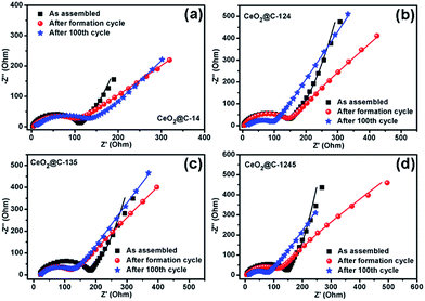 |
| | Fig. 11 Electrochemical impedance spectra (EIS) of (a) CeO2@C-14, (b) CeO2@C-124, (c) CeO2@C-135 and (d) CeO2@C-1245 at different cycling stages. | |
The fitted impedance data are given in Table 1. In the high frequency region, intercept on the real axis (Z′) denotes the solution resistance (Rs) consisting of intrinsic resistance of the electrode material, ionic resistance and contact resistance between the electrode and current collector. All the CeO2@C cells show a low Rs value of ∼3 Ω except for CeO2@C-135 (16 Ω).
Table 1 Fitted impedance data
| Cycling intervals |
R
s (ohm) |
R
SEI (ohm) |
R
ct (ohm) |
C
SEI (μF) |
Q (CPE) (μF) |
Diffusion admittance, Y0 (mMho) [W] |
C (mF) |
| CeO2@C-14 |
| As assembled |
2.6 |
— |
111 |
— |
4.7 |
5.9 |
19.4 |
| After formation cycle |
4.4 |
2.6 |
107 |
5.2 |
6.4 |
7.1 |
— |
| After 100th cycle |
7.7 |
4.8 |
137 |
3.6 |
5.1 |
9.2 |
— |
|
|
CeO
2
@C-124
|
| As assembled |
2.8 |
— |
137 |
— |
4.9 |
4.4 |
11.8 |
| After formation cycle |
5.3 |
3.8 |
142 |
3.9 |
5.7 |
6.5 |
— |
| After 100th cycle |
13.4 |
5.2 |
91.6 |
2.2 |
3.3 |
7.5 |
— |
|
|
CeO
2
@C-135
|
| As assembled |
16 |
— |
151 |
— |
4.0 |
7.4 |
6.9 |
| After formation cycle |
22.3 |
4.2 |
101 |
2.2 |
5.5 |
7.8 |
— |
| After 100th cycle |
23 |
6.6 |
108 |
1.7 |
4.7 |
9.6 |
— |
|
|
CeO
2
@C-1245
|
| As assembled |
3.1 |
— |
132 |
— |
4.9 |
6.0 |
12.8 |
| After formation cycle |
3.4 |
3.6 |
120 |
3.7 |
5.2 |
7.4 |
— |
| After 100th cycle |
11.5 |
4.8 |
65 |
3.3 |
4.3 |
8.4 |
— |
Also, Rs does not increase significantly after 100 cycles indicating good stability of the electrode. The diameter of the depressed semicircle, formed up to the mid-frequency region, represents the charge transfer resistance (Rct). The Rct value is found to be the lowest (111 Ω) for CeO2@C-14 (containing 26.8 wt% embedded carbon), while it is the highest (151 Ω) for CeO2@C-135 (containing 7.9 wt% embedded carbon). No drastic increase in Rct is observed with cycling explaining the steady cycling performance of the CeO2@C cells. The sharp straight line from the mid-frequency to the low frequency region can be linked to the Warburg resistance (W) which is related to the ionic diffusion in the electrolyte/electrode interface. In the as-assembled state, the Warburg line shows a deviation from the usual intercept angle of 45° and tends to become parallel to the Y-axis. This may have resulted from the capacitive nature of these MOF derived materials forming Helmholtz double layers in the as-assembled state. However, after the formation cycle, the Warburg line approaches 45°. Also, from the diffusion admittance (Y0) values, which is inversely related to W, it is found that the diffusion process becomes faster with cycling. In order to examine the change in the morphology upon cycling, an ex situ FESEM study was undertaken.
It is observed that the particles are not agglomerated and retains the overall sizes and shape, but the inner structure underwent a considerable change forming a cage-like structure with interconnected thin plates (Fig. 12). This may have resulted through interpenetration and consequent assembly of the constituent nanobars. During the formation of Ce-1,4-BDC MOF, the spherical morphology was formed due to the self-assembly of nanobars in the presence of PVP, a morphology directing agent. This basic spherical morphology of Ce-1,4-BDC MOF is inherited by CeO2@C-14. However, during repeated lithiation/delithiation processes under a potential gradient; the nanobars may reorient themselves in a plate-like assembly to allow the smooth passage of ionic species. This could lead to the gradual roughening of the surface ultimately leading creation of open tunnels within the spherical shape after 100 consecutive cycles. Such kind of open tunnel structure would also explain the increased diffusion admittance with cycling as observed in the EIS study.
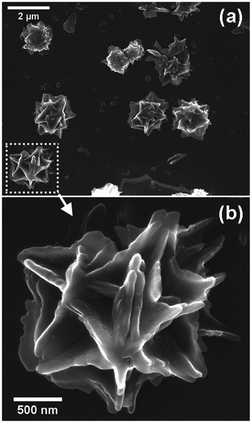 |
| | Fig. 12 FESEM images of (a and b) CeO2@C-14 after 100 discharge–charge cycles. | |
Conclusions
In summary, we have described a facile MOF derived synthesis route for carbon embedded CeO2. By varying the organic linker and using PVP as the structure directing agent, shape-specific morphology could be pre-designed. A comparative performance analysis among three different shapes reveals that the spherically shaped CeO2@C-14 shows the best results with a maximum specific capacity of 715 mA h g−1 at 0.05 mA cm−2, good rate performance (413 mA h g−1 at 0.5 mA cm−2) and cycling stability with a low fading rate of 0.06% per cycle. Such excellent performance can be attributed to the morphological advantages through the MOF route and presence of an in situ generated carbon matrix that serves as a conducting network for charge transport as well as a buffer for accommodating the volume changes. The present findings may also be useful for designing other metal oxides with desired morphological features.
Acknowledgements
The authors thank Director, CSIR-CGCRI for kind permission to publish this work. S. Maiti thanks CSIR India for a senior research fellowship. Financial support from SERB, DST India vide project number EMR/2104/000729 is gratefully acknowledged.
References
- P. Poizot, S. Laruelle, S. Grugeon, L. Dupont and J. M. Tarascon, Nature, 2000, 407, 496–499 CrossRef CAS PubMed.
- J. M. Tarascon and M. Armand, Nature, 2001, 414, 359–367 CrossRef CAS PubMed.
- A. Pan, J.-G. Zhang, Z. Nie, G. Cao, B. W. Arey, G. Li, S.-Q. Liang and J. Liu, J. Mater. Chem., 2010, 20, 9193–9199 RSC.
- J. Liu, H. Xia, D. Xue and L. Lu, J. Am. Chem. Soc., 2009, 131, 12086–12087 CrossRef CAS PubMed.
- A.-M. Cao, J.-S. Hu, H.-P. Liang and L.-J. Wan, Angew. Chem., Int. Ed., 2005, 44, 4391–4395 CrossRef CAS PubMed.
- N. Mahmood, C. Zhang and Y. Hou, Small, 2013, 9, 1321–1328 CrossRef CAS PubMed.
- S. Maiti, A. Pramanik and S. Mahanty, CrystEngComm, 2016, 18, 450–461 RSC.
- Q. Hao, J. Wang and C. Xu, J. Mater. Chem. A, 2014, 2, 87–93 CAS.
- G. Jian, Y. Xu, L.-C. Lai, C. Wang and M. R. Zachariah, J. Mater. Chem. A, 2014, 2, 4627–4632 CAS.
- H. Wang, L. F. Cui, Y. Yang, H. S. Casalongue, J. T. Robinson, Y. Liang, Y. Cui and H. Dai, J. Am. Chem. Soc., 2010, 132, 13978–13980 CrossRef CAS PubMed.
- X. Zhang, H. Liu, S. Petnikota, S. Ramakrishnab and H. J. Fan, J. Mater. Chem. A, 2014, 2, 10835–10841 CAS.
- J. Xin, C. J. Jia, X. J. Hui, S. Y. Ning, F. Y. Zuo, Z. M. Sen and D. Q. Feng, Chem. Commun., 2012, 48, 7410–7412 RSC.
- X. Xu, R. Cao, S. Jeong and J. Cho, Nano Lett., 2012, 12, 4988 CrossRef CAS PubMed.
- X. Li, X. Huang, D. Liu, X. Wang, S. Song, L. Zhou and H. Zhang, J. Phys. Chem. C, 2011, 115, 21567–21573 CAS.
- C. He, S. Wu, N. Zhao, C. Shi, E. Liu and J. Li, ACS Nano, 2013, 7, 4459–4469 CrossRef CAS PubMed.
- L. Shen, H. Song, H. Cui, X. Wen, X. Wei and C. Wang, CrystEngComm, 2013, 15, 9849–9854 RSC.
- Y. Sun, X. Hu, W. Luo and Y. Huang, J. Mater. Chem., 2012, 22, 13826–13831 RSC.
- A. Pramanik, S. Maiti, M. Sreemany and S. Mahanty, J. Nanopart. Res., 2016, 18, 93 CrossRef.
- M. Zhang, F. Yan, X. Tang, Q. Li, T. Wang and G. Cao, J. Mater. Chem. A, 2014, 2, 5890–5897 CAS.
- C. Peng, B. Chen, Y. Qin, S. Yang, C. Li, Y. Zuo, S. Liu and J. Yang, ACS Nano, 2012, 6, 1074–1081 CrossRef CAS PubMed.
- Y. Wang, H. J. Zhang, L. Lu, L. P. Stubbs, C. C. Wong and J. Lin, ACS Nano, 2010, 4, 4753–4761 CrossRef CAS PubMed.
- B. Li, H. Cao, J. Shao, G. Li, M. Qu and G. Yin, Inorg. Chem., 2011, 50, 1628–1632 CrossRef CAS PubMed.
- S. Xiong, J. S. Chen, X. W. Lou and H. C. Zeng, Adv. Funct. Mater., 2012, 22, 861–871 CrossRef CAS.
- L. Tao, J. Zai, K. Wang, Y. Wan, H. Zhang, C. Yu, Y. Xiao and X. Qian, RSC Adv., 2012, 2, 3410–3415 RSC.
- Y. Zou and Y. Wang, Nanoscale, 2011, 3, 2615–2620 RSC.
- Y. Huang, X.-I. Huang, J.-S. Lian, D. Xu, L.-M. Wanga and X.-B. Zhang, J. Mater. Chem., 2012, 22, 2844–2847 RSC.
- S.-F. Zheng, J.-S. Hu, L.-S. Zhong, W.-G. Song, L.-J. Wan and Y.-G. Guo, Chem. Mater., 2008, 20, 3617–3622 CrossRef CAS.
- W. Zhang, Z. Zhou, W. Zhao, Z. Yang and X. Yang, J. Mater. Chem. A, 2014, 2, 5800–5808 CAS.
- H. Wang, Q. Pan, J. Zhao, G. Yin and P. Zuo, J. Power Sources, 2007, 167, 206–211 CrossRef CAS.
- J. Lin, Z. Peng, C. Xiang, G. Ruan, Z. Yan, D. Natelson and J. M. Tour, ACS Nano, 2013, 7, 6001–6006 CrossRef CAS PubMed.
- K. Kravchyk, L. Protesescu, M. I. Bodnarchuk, F. Krumeich, M. Yarema, M. Walter, C. Guntlin and M. V. Kovalenko, J. Am. Chem. Soc., 2013, 135, 4199–4202 CrossRef CAS PubMed.
- L. Yu, D. Cai, H. Wang and M.-M. Titirici, RSC Adv., 2013, 3, 17281–17286 RSC.
- G. M. Hua, L. D. Zhang, G. T. Fei and M. Fang, J. Mater. Chem., 2012, 22, 6851–6855 RSC.
- R. J. Qi, Y. J. Zhu, G. F. Cheng and Y. H. Huang, Nanotechnology, 2005, 16, 2502 CrossRef CAS.
- M. Balaguer, V. B. Vert, L. Navarrete and J. M. Serra, J. Power Sources, 2013, 223, 214–220 CrossRef CAS.
- A. Primo, T. Marino, A. Corma, R. Molinari and H. Garcia, J. Am. Chem. Soc., 2011, 133, 6930–6933 CrossRef CAS PubMed.
- M. Burbano, S. T. Norberg, S. Hull, S. G. Eriksson, D. Marrocchelli, P. A. Madden and G. W. Waton, Chem. Mater., 2012, 24, 222–229 CrossRef CAS.
- X. Wang, D. P. Liu, S. Y. Song and H. J. Zhang, J. Am. Chem. Soc., 2013, 135, 15864–15872 CrossRef CAS PubMed.
- N. Zouaoui, M. Issa, D. Kehrli and M. Jeguirim, Catal. Today, 2012, 189, 65–69 CrossRef CAS.
- Y. Yang, C. G. Tian, L. Sun, R. J. Lu, W. Zhou, K. Y. Shi, K. Kan, J. C. Wang and H. G. Fu, J. Mater. Chem. A, 2013, 1, 12742–12749 CAS.
- H. Y. Kim, H. M. Lee and G. HenKelman, J. Am. Chem. Soc., 2012, 134, 1560–1570 CrossRef CAS PubMed.
- Q. Su, L. Chang, J. Zhang, G. Du and B. Xu, J. Phys. Chem. C, 2013, 117, 4292–4298 CAS.
- F. Zhou, X. Ni, Y. Zhang and H. Zheng, J. Colloid Interface Sci., 2007, 307, 135–138 CrossRef CAS PubMed.
- F. Zhou, X. Zhao, H. Xu and C. Yuan, J. Phys. Chem. C, 2007, 111, 1651–1657 CAS.
- G. Wang, J. Bai, Y. Wang, Z. Rena and J. Bai, Scr. Mater., 2011, 65, 339–342 CrossRef CAS.
- R. Guo, W. Yue, Y. Ren and W. Zhou, Mater. Res. Bull., 2016, 73, 102–110 CrossRef CAS.
- X. Wu, H. Niu, S. Fu, J. Song, C. Mao, S. Zhang, D. Zhang and C. Chen, J. Mater. Chem. A, 2014, 2, 6790–6795 CAS.
- H. Liu and H. Liu, Mater. Lett., 2016, 168, 80–82 CrossRef CAS.
- H. Pang and C. Chen, RSC Adv., 2014, 4, 14872–14878 RSC.
- H. Liu and Q. Le, J. Alloys Compd., 2016, 669, 1–7 CrossRef CAS.
- C. Cheng, F. Chen, H. Yi and G. Lai, J. Alloys Compd., 2017, 694, 276–281 CrossRef CAS.
- H. Liu and H. Liu, J. Alloys Compd., 2016, 681, 342–349 CrossRef CAS.
- H. Liu, H. Liu and X. Han, J. Solid State Electrochem., 2017, 21, 291–295 CrossRef CAS.
- L. Wang, X. Zhang and K. Chen, CrystEngComm, 2013, 15, 4860–4864 RSC.
- H. Jiang, T. Sun, C. Li and J. Ma, J. Mater. Chem., 2012, 22, 2751–2756 RSC.
- L. Hu, H. Zhong, X. Zheng, Y. Huang, P. Zhang and Q. C. Hefei, Sci. Rep., 2012, 2, 986 Search PubMed.
- D. Yu, B. Wu, L. Ge, L. Wu, H. Wang and T. Xu, J. Mater. Chem. A, 2016, 4, 10878–10884 CAS.
- D. Tian, X.-L. Zhou, Y.-H. Zhang, Z. Zhou and X.-H. Bu, Inorg. Chem., 2015, 54, 8159–8161 CrossRef CAS PubMed.
- Y. Zhao, X. Li, J. Liu, C. Wang, Y. Zhao and G. Yue, ACS Appl. Mater. Interfaces, 2016, 8, 6472–6480 CAS.
- V. Soundharrajan, B. Sambandam, J. Song, S. Kim, J. Jo, S. Kim, S. Lee, V. Mathew and J. Kim, ACS Appl. Mater. Interfaces, 2016, 8, 8546–8553 CAS.
- S. Maiti, A. Pramanik and S. Mahanty, Chem. Commun., 2014, 50, 11717–11720 RSC.
- S. Maiti, A. Pramanik, U. Manju and S. Mahanty, ACS Appl. Mater. Interfaces, 2015, 7, 16357–16363 CAS.
- M. Zhu, W. Fu and G. Zou, J. Coord. Chem., 2012, 65, 4108–4114 CrossRef CAS.
- K. Liu, H. You, G. Jia, Y. Zheng, Y. Huang, Y. Song, M. Yang, L. Zhang and H. Zhang, Cryst. Growth Des., 2010, 10, 790–797 CAS.
- M.-J. Ren, Z. Zhang, P. Zhao and J. Zhang, Asian J. Chem., 2008, 20, 3687–3701 CAS.
- W. J. Rieter, K. M. L. Taylor, H. An, W. Lin and W. Lin, J. Am. Chem. Soc., 2006, 128, 9024–9025 CrossRef CAS PubMed.
- Y. Lin, Q. Zhang, C. Zhao, H. Li, C. Kong, C. Shen and L. Chen, Chem. Commun., 2015, 51, 697–699 RSC.
- J. Matta, D. Courcot, E. Abi-Aad and A. Aboukais, Chem. Mater., 2002, 14, 4118–4125 CrossRef CAS.
- M. A. Pimenta, G. Dresselhaus, M. S. Dresselhaus, L. G. Cancado, A. Jorio and R. Saito, Phys. Chem. Chem. Phys., 2007, 9, 1276–1291 RSC.
- L. G. Cançado, A. Jorio and M. A. Pimenta, Phys. Rev. B: Condens. Matter Mater. Phys., 2007, 76, 064304 CrossRef.
- K. Liu, H. You, Y. Zheng, G. Jia, Y. Huang, M. Yang, Y. Song, L. Zhang and H. Zhang, Cryst. Growth Des., 2010, 10, 16–19 CAS.
- K. Liu, H. You, G. Jia, Y. Zheng, Y. Song, M. Yang, Y. Huang and H. Zhang, Cryst. Growth Des., 2009, 9, 3519–3524 CAS.
- L.-N. Jin, Q. Liu, Y. Lu and W.-Y. Sun, CrystEngComm, 2012, 14, 3515–3520 RSC.
- V. Stetsovych, F. Pagliuca, F. Dvorak, T. Duchon, M. Vorokhta, M. Aulicka, J. Lachnitt, S. Schernich, I. Matolinova, K. Veltruska, T. Skala, D. Mazur, J. Myslivecek, J. Libuda and V. Matolin, J. Phys. Chem. Lett., 2013, 4, 866–871 CrossRef CAS PubMed.
- L. Liao, H. X. Mai, Q. Yuan, H. B. Lu, J. C. Li, C. Liu, C. H. Yan, Z. X. Shen and T. Yu, J. Phys. Chem. C, 2008, 112, 9061–9065 CAS.
- A. Allahgholi, J. I. Flege, S. Thieß, W. Drube and J. Falta, ChemPhysChem, 2015, 16, 1083–1091 CrossRef CAS PubMed.
- E. Beche, P. Charvin, D. Perarnau, S. Abanades and G. Flamant, Surf. Interface Anal., 2008, 40, 264–267 CrossRef CAS.
- L. Liao, H. X. Mai, Q. Yuan, H. B. Lu, J. C. Li, C. Liu, C. H. Yan, Z. X. Shen and T. Yu, J. Phys. Chem. C, 2008, 112, 9061–9065 CAS.
- R. L. Sacci, J. M. Black, N. Balke, N. J. Dudney, K. L. More and R. R. Unocic, Nano Lett., 2015, 15, 2011–2018 CrossRef CAS PubMed.
- P. Ganesh, P. R. C. Kent and D. Jiang, J. Phys. Chem. C, 2012, 116, 24476–24481 CAS.
- H.-M. Cho, Y. J. Park, J.-W. Yeon and H.-C. Shin, Electron. Mater. Lett., 2009, 5, 169–178 CrossRef CAS.
- J. Fan and S. Tan, J. Electrochem. Soc., 2006, 153, A1081 CrossRef CAS.
- D. P. Abraham, J. L. Knuth, D. W. Dees, I. Bloom and J. P. Christophersen, J. Power Sources, 2007, 170, 465 CrossRef CAS.
- D. P. Abraham, J. R. Heaton, S.-H. Kang, D. W. Dees and A. N. Jansen, J. Electrochem. Soc., 2008, 155, A41 CrossRef CAS.
- J. Huang and Z. Jiang, Electrochim. Acta, 2008, 53, 7756 CrossRef CAS.
Footnote |
| † Electronic supplementary information (ESI) available: Synthesis scheme, FTIR spectra of MOFs, XRD analysis data, TGA, Raman spectra, Raman spectra analysis data, molecular structures of ligands, possible metal–ligand co-ordination in MOFs, additional FESEM micrographs of MOFs, N2 adsorption–desorption isotherm and pore size distribution, electrochemical study of Super P carbon, equivalent circuit models, Comparison of electrochemical results with the literature. See DOI: 10.1039/c6se00026f |
|
| This journal is © The Royal Society of Chemistry 2017 |

 *a
*a