 Open Access Article
Creative Commons Attribution 3.0 Unported Licence
Exploring the full catalytic cycle of rhodium(I)–BINAP-catalysed isomerisation of allylic amines: a graph theory approach for path optimisation†
Takayoshi
Yoshimura
a,
Satoshi
Maeda
 *b,
Tetsuya
Taketsugu
 b,
Masaya
Sawamura
 b,
Keiji
Morokuma
*c and
Seiji
Mori
 *a
*a
aInstitute of Quantum Beam Science, Ibaraki University, Mito 310-8512, Japan. E-mail: seiji.mori.compchem@vc.ibaraki.ac.jp
bDepartment of Chemistry, Faculty of Science, Hokkaido University, Kita-10, Nishi-8, Kita-ku, Sapporo 060-0810, Japan. E-mail: smaeda@eis.hokudai.ac.jp
cFukui Institute for Fundamental Chemistry, Kyoto University, 34-4 Takano Nishihiraki-cho, Sakyo, Kyoto 606-8103, Japan. E-mail: morokuma.keiji.3a@kyoto-u.ac.jp
First published on 3rd May 2017
Abstract
We explored the reaction mechanism of the cationic rhodium(I)–BINAP complex catalysed isomerisation of allylic amines using the artificial force induced reaction method with the global reaction route mapping strategy, which enabled us to search for various reaction paths without assumption of transition states. The entire reaction network was reproduced in the form of a graph, and reasonable paths were selected from the complicated network using Prim’s algorithm. As a result, a new dissociative reaction mechanism was proposed. Our comprehensive reaction path search provided rationales for the E/Z and S/R selectivities of the stereoselective reaction.
1 Introduction
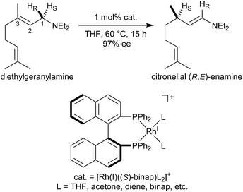
Noyori et al. reported the BINAP–metal-catalysed hydrogenation reaction of enamides with excellent enantioselectivity; we have previously examined the mechanisms of this reaction using the quantum mechanics/molecular mechanics (QM/MM) method.1–7 Otsuka et al. reported a highly regioselective and enantioselective 1,3-hydrogen shift reaction of allylic amines using a cationic rhodium(I)–BINAP catalyst (Fig. 1).8–13 The asymmetric 1,3-hydrogen shift of diethylgeranylamine forms a corresponding citronellal (R,E)-enamine, which generates a stereogenic carbon centre from a prochiral compound. This reaction has been used in the stereoselective synthesis of L-menthol.14 In addition, the isomerisation includes a C–H bond cleavage step. Thus, knowledge of the mechanism of this reaction would be highly meaningful in the context of metal-catalysed C–H functionalisation chemistry.15Three reaction mechanisms have previously been reported based on experimental and computational studies (Fig. 2).16–18 All of these mechanisms start from the bis-solvent coordinate Rh(I)–BINAP complex I, and the bis-substrate coordinate complex II is formed through ligand substitution. The difference in the three mechanisms lies in the C(1)–H σ-bond cleavage step. The first mechanism, proposed by Noyori, is a dissociative mechanism and includes the formation of the transient iminium–Rh(I)-hydride complex IV through β-hydride elimination from the mono-amine coordinate complex III.16 Complex IV is converted to the η3-enamine coordinate complex V by the transfer of a hydride from the rhodium to C(3). Ligand substitution from complex V forms complex II or complex III through the bis-amine coordinate Rh(I) complex VI. However, ab initio molecular orbital studies showed that the associative mechanism is more advantageous than Noyori’s dissociative mechanism.17 A second mechanism, Takaya and Noyori’s mechanism, was then proposed. They suggested that the C(1)–H oxidative addition occurs directly from complex II without liberation of an NR3 molecule. This mechanism involves a Rh(I)/Rh(III) two-electron-redox process through a characteristic distorted-octahedral Rh(III) hydride complex VII. Complex VI is formed by reductive elimination from complex VII. Later, Ujaque and Espinet proposed a more reasonable allylmetal mechanism based on density functional theory (DFT) studies.18 This mechanism begins with intramolecular isomerisation of κ1-(N)-coordinate complex II to η2-(C![[double bond, length as m-dash]](https://www.rsc.org/images/entities/char_e001.gif) C)-coordinate complex VIII, which then undergoes C(1)–H σ-bond cleavage to form distorted-octahedral η3-allyl complex IX. After a conformational exchange from IX to X, the reaction concludes with reductive elimination to form complex VI.
C)-coordinate complex VIII, which then undergoes C(1)–H σ-bond cleavage to form distorted-octahedral η3-allyl complex IX. After a conformational exchange from IX to X, the reaction concludes with reductive elimination to form complex VI.
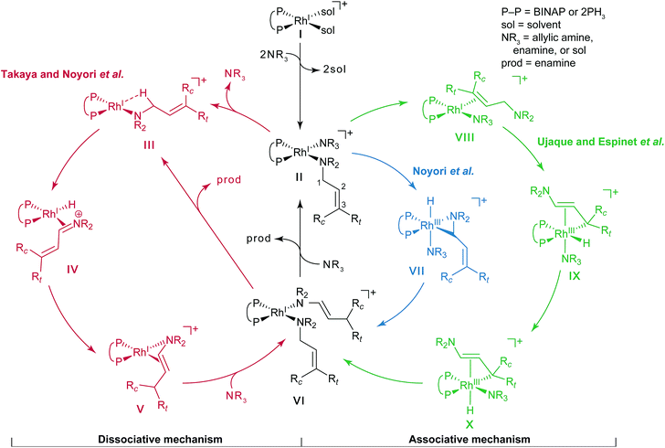 | ||
| Fig. 2 Three catalytic cycles in the literature: the routes proposed by Takaya and Noyori et al. (red), Noyori et al. (blue), and Ujaque and Espinet et al. (green). | ||
The three mechanisms were proposed based on assumptions of the intermediates and transition states (TSs). To eliminate the need for this assumption to allow exploration of the reaction paths, we used a reaction path search method called artificial force induced reaction (AFIR), which can algorithmically predict reaction paths and TSs on reaction paths. To analyse a complicated reaction path network obtained using the AFIR method, Prim’s algorithm was employed. Although kinetic approaches such as rate constant matrix contraction19,20 and kinetic Monte Carlo21–23 have been used in evaluating quantities such as overall rate constants and branching ratios, graph theory approaches including Prim’s algorithm would be useful to visualise an overview of highly multistep reaction paths. Furthermore, our own N-layered integrated molecular orbital + molecular mechanics (ONIOM) method was employed to reduce the computational cost, which enabled us to use the structure of the Rh(I)–BINAP complex without replacing the functional groups. In the studies by Noyori et al.17 and Ujaque and Espinet et al.,18 two PH3 molecules were used as a model of the BINAP ligand for the same purpose; as a result of this simplification, the associative mechanism appeared to be the most viable. However, our results, without simplification of the Rh(I)–BINAP complex, demonstrated the advantages of the dissociative mechanism over the associative mechanism.
2 Computational methods
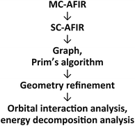
2.1 Outline of the computational procedure
An outline of our computational procedure is shown in Fig. 3. We employed the AFIR method coded in the global reaction route mapping (GRRM) programme to explore the reaction path network.24–31 There are two modes for the AFIR method. In the multi-component mode (MC-AFIR), the force is applied between two or more reactant molecules to induce a reaction between the reactants. In the single-component mode (SC-AFIR), fragments are defined automatically in an entire system (molecule or complex) and the force is applied between the fragments. In this study, the MC-AFIR and SC-AFIR were used, respectively, in the coordination state sampling and in the path sampling within the coordination complexes. The graph consists of connections between nodes and edges. In the present study, a node and an edge represent a local minimum (LM) and a TS, respectively. Prim’s algorithm was employed to construct a minimum spanning tree (MST) from the graph. Examination of the algorithm procedure demonstrates that the MST shows energetically reasonable paths. Finally, some LMs and TSs were reoptimised and analysed at higher computational levels for more detailed study.2.2 Coordination state search with the MC-AFIR method
The models that we considered are shown in Fig. 4. The full cationic Rh(I)–BINAP complex XI was used as a catalyst. To simplify the models of the substrates, N,N,3-trimethylbut-2-en-1-amine XII and trimethylamine XIII were used as the substrates. To examine the enantiotopic face, two methyl groups on the allylic group were indicated as Rt (trans) and Rc (cis); the priority of Rt was established to be higher than that of Rc. The ONIOM-type hybrid QM/MM model was employed to reduce the computational cost.32–39 The QM and MM regions in the ONIOM method were defined as given in Fig. 4. The MM region was treated at the universal force field (UFF) level, while the QM region was treated at the B3LYP level in conjunction with the LANL2DZ basis set for the rhodium atom and the 6-31G basis set for other atoms (BS1).40–43 The initial geometries of the fragments were optimised, respectively, at the B3LYP/BS1 level. Electrostatic potential (ESP) atomic charges for the MM region were calculated for each fragment at the same level as the geometry optimisation of the fragments; the ESP atomic charges were fixed while the AFIR search was performed. We considered the dissociative mechanism and the associative mechanism separately. In the dissociative mechanism, the cationic Rh(I)–BINAP complex X and the allylic amine XI were included in the computational model, and the artificial forces were applied between the fragments (X and XI). In the associative mechanism, the trimethylamine XII was appended to the computational model of the dissociative mechanism, and artificial forces were applied between three fragments (X, XI and XII). The AFIR search was initiated from randomly generated initial orientations and directions of the fragments; this type of AFIR search is called MC-AFIR. The γ value for the MC-AFIR search was set to 300 kJ mol−1. The path sampling in the MC-AFIR search was terminated when the last ten new AFIR paths resulted in AFIR paths found earlier. All approximate LMs and TSs obtained with the MC-AFIR search were fully optimised without artificial forces at the ONIOM level.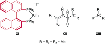 | ||
| Fig. 4 Computational models. Artificial force was applied between the atoms marked with asterisks. The MM region is depicted in red and the QM region is depicted in black. | ||
2.3 Reaction path search with the SC-AFIR method
After the MC-AFIR search was performed, we applied an SC-AFIR search, which is suitable for finding stepwise paths. The computational level for the SC-AFIR search was the same as for the MC-AFIR search. The initial structures for the SC-AFIR search were selected from the results of the MC-AFIR search; each selected LM was found to be the precursor of the C(1)–H bond cleavage step. All approximate LMs and TSs obtained with SC-AFIR were fully optimised without artificial force at the ONIOM level. After the MC-AFIR and SC-AFIR searches, the connections between the LMs and TSs were verified by intrinsic reaction coordinate (IRC) analysis from each TS.44 During the search, the artificial force is applied, and paths are somewhat deviated from actual LMs, TSs and IRCs. We emphasise that the LMs, TSs and IRCs finally obtained and discussed below are “actual” local minima, first-order saddle points, and steepest descent paths in the mass-weighted coordinate, respectively, on the adiabatic potential energy surface. Both AFIR searches were performed with a developmental version of the GRRM programme; the energies, gradients and Hessians were computed with Gaussian 09 (Rev. D01).31,45 Technical details of the MC-AFIR and SC-AFIR methods and their recent applications to organic reactions can be found in recent review papers.46,472.4 Representation of the reaction network and extraction of the reaction path
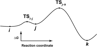
After the comprehensive search for reaction paths is complete, the remaining problems are to understand the entire reaction network and to select probable paths from the greatly extended reaction network. We showed the reaction network in the form of graph G (Fig. 5). A vertex and an edge represent a LM and a TS, respectively. A number of paths from an arbitrary vertex to another vertex are combinations of the edges. If the numbers of vertices and edges increase, finding probable paths becomes much more difficult because of the exponential growth of the number of combinations. Therefore, we applied Prim’s algorithm to solve the combination problem.48 The algorithm accepts a graph G and outputs a tree T by repeating a selection of an edge with a smaller weight. If the energy of the TS is used as the weight of the edge, the algorithm is applicable to obtain a tree T of reaction paths. Because there is a unique path from a starting point to another point in this tree T, the discussion of the reaction paths becomes easy to understand. The concrete procedure is as follows. 1: select an arbitrary vertex from the graph G, which becomes a starting point of the reaction (e.g. vertex 1 is selected in Fig. 5(b)). 2: select a vertex which has not been selected previously and which is connected to the selected vertex. If there is more than one possible edge, the most stable one is selected (e.g. three edges connect to vertex 1 in Fig. 5(c). The most stable edge is 1–2; thus, it will be selected). 3: select a vertex which has not been selected previously and which is connected to the vertex in the set of selected vertices (Fig. 5(d)). If there is more than one possible edge, the most stable one is selected. 4: perform step 3 as many times as possible. Finally, by this procedure, we can draw a tree T in which the edge with the highest weight is excluded (Fig. 5(e)). This algorithm is known to provide an MST which is uniquely formed from a network. Thus, any vertex can be selected as the starting point. In the present study, the first vertex was chosen from a vertex with a maximum degree (maximum number of edges connected to the vertex). The numbers of the vertices were arranged in the order of the vertex chosen by Prim’s algorithm. Using this order, the smaller number is given to a vertex which passes through energetically lower TSs from the starting vertex. The Gephi programme was employed to illustrate the graphs.49 The Gibbs free energies at the ONIOM(B3LYP/BS1:UFF) level (25 °C) were used for the analysis of the reaction paths.Here, the notations of the LM and the TS are explained. The number of the LM is decided according to Prim’s algorithm, and the LM itself is represented by this number (e.g. i, j, k in Fig. 6). The TS which connects i and j is written as TSi–j. Some reaction steps were discussed together. For example, in Fig. 6, if a reaction path from i to k is discussed, both LMs and a TS with the highest energy (TSj–k) in the path are focused on. To indicate both ends clearly, notation such as TSj–k (i → k) is introduced.
2.5 Full DFT optimisation and single point energy calculations
Some LMs and TSs which were selected from the results of the MC-AFIR and the SC-AFIR reaction path searches were reoptimised without the ONIOM model. The dispersion-corrected B3LYP + D3 functional in conjunction with the Stuttgart/Dresden effective core potentials, the associated SDD basis set for a rhodium atom, and the 6-31G(d) basis sets for the other atoms (BS2) were employed for the entire system.50–52 After geometry optimisation, IRC calculations were performed to confirm that the TS is connected to the correct LMs.44Single point energy calculations were performed with the same functional as that used for the full DFT geometry optimisation. The BS2 basis sets were replaced with a triple zeta valence polarisation basis set, def2-TZVP (BS3).53,54 A polarised continuum model using the integral equation formalism variant (IEF-PCM) with a dielectric constant of ε = 7.4257 (THF) was employed to estimate the energetics in solution.55–57 Thus, the present computational level is denoted B3LYP + D3(PCM)/BS3//B3LYP + D3/BS2. To analyse the orbital interactions, natural bond orbital (NBO) analysis was performed at the same level.58
2.6 Energy decomposition analysis
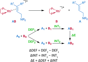
Energy decomposition analysis (EDA) was performed for the key TSs of the stereochemistry-determining step.59,60 The B3LYP + D3(PCM)/BS3 level was employed for the EDA. The structures of the rhodium complexes were divided into the allylic amine region (A) and the cationic rhodium(I)–BINAP region (B), as shown in Fig. 7. The deformation energy (DEF) is the sum of the deformation energy of A (DEFA, defined as the energy of A at the optimised structure of the complex relative to that of the optimised isolated structure A0) and that of B (DEFB). INT indicates the interaction energy between A and B at the optimised structure of a complex AB. The energy difference (ΔE) between the two optimised structures, AB1 and AB2, can be written as a sum of the ΔDEF and the ΔINT. The electronic structure calculations described in the last two sections were performed with Gaussian 09 (Rev. D01).453 Results and discussion
3.1 Coordination states of the BINAP–rhodium(I)–allylamine complex (results of the MC-AFIR method)
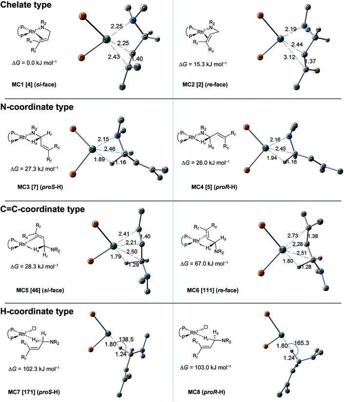
The MC-AFIR coordination searches for the dissociative mechanism provided four types with two diastereomers in each type (Fig. 8); the searches for the associative mechanism provided one type with two diastereomers (Fig. 9).In the dissociative mechanism, the chelate complex MC1 is the most energetically stable LM. The C![[double bond, length as m-dash]](https://www.rsc.org/images/entities/char_e001.gif) C double bond of the substrate in MC1 coordinates to the Rh(I) centre from the si-face. Another chelate complex, MC2 (ΔG = 15.3 kJ mol−1), whose C
C double bond of the substrate in MC1 coordinates to the Rh(I) centre from the si-face. Another chelate complex, MC2 (ΔG = 15.3 kJ mol−1), whose C![[double bond, length as m-dash]](https://www.rsc.org/images/entities/char_e001.gif) C double bond is coordinated from the re-face, is an energetically higher LM than MC1 (ΔG = 0.0 kJ mol−1). Next, the stable LMs are classified into N-coordinate types (MC3 and MC4); these have a Rh(I)–N coordinated bond and a Rh(I)⋯H–C(1) interaction. The coordination mode between the Rh(I) centre and the H–C(1) σ-bond forms a side-on geometry, and the H–C bond distance (1.16 Å) is longer than the general H–C bond distance (1.10 Å), showing a typical agostic interaction.61 The energy difference between the complexes MC3 and MC4 is very small (ΔG = 1.3 kJ mol−1). The next type is a C
C double bond is coordinated from the re-face, is an energetically higher LM than MC1 (ΔG = 0.0 kJ mol−1). Next, the stable LMs are classified into N-coordinate types (MC3 and MC4); these have a Rh(I)–N coordinated bond and a Rh(I)⋯H–C(1) interaction. The coordination mode between the Rh(I) centre and the H–C(1) σ-bond forms a side-on geometry, and the H–C bond distance (1.16 Å) is longer than the general H–C bond distance (1.10 Å), showing a typical agostic interaction.61 The energy difference between the complexes MC3 and MC4 is very small (ΔG = 1.3 kJ mol−1). The next type is a C![[double bond, length as m-dash]](https://www.rsc.org/images/entities/char_e001.gif) C-coordinated type. C
C-coordinated type. C![[double bond, length as m-dash]](https://www.rsc.org/images/entities/char_e001.gif) C-coordination from the si-face and re-face directions forms the C
C-coordination from the si-face and re-face directions forms the C![[double bond, length as m-dash]](https://www.rsc.org/images/entities/char_e001.gif) C-coordinate Rh(I) complexes MC5 and MC6, respectively. Both complexes also have agostic interactions. The π-coordination bond of C(2)
C-coordinate Rh(I) complexes MC5 and MC6, respectively. Both complexes also have agostic interactions. The π-coordination bond of C(2)![[double bond, length as m-dash]](https://www.rsc.org/images/entities/char_e001.gif) C(3) is inclined toward the C(2) atom because the agostic interaction attracts the Rh(I) atom to the H–C(1) σ-bond. There is a large energy difference between MC5 and MC6 (ΔG = 38.7 kJ mol−1), which will be discussed in Section 3.3.4. The last type of complex has a Rh(I)⋯H–C(1) interaction and a vacant coordination position on the Rh(I) atom (MC7 and MC8). The rhodium atom of MC7 interacts with the pro-S-hydrogen atom, while that of MC8 interacts with the pro-R-hydrogen atom. The Rh(I)⋯H–C(1) of both complexes is linear. Thus, this interaction is classified as an anagostic interaction.61 The four agostic complexes (MC3, MC4, MC5 and MC6) were selected as the initial structures for the SC-AFIR reaction path searches of the dissociative mechanism.
C(3) is inclined toward the C(2) atom because the agostic interaction attracts the Rh(I) atom to the H–C(1) σ-bond. There is a large energy difference between MC5 and MC6 (ΔG = 38.7 kJ mol−1), which will be discussed in Section 3.3.4. The last type of complex has a Rh(I)⋯H–C(1) interaction and a vacant coordination position on the Rh(I) atom (MC7 and MC8). The rhodium atom of MC7 interacts with the pro-S-hydrogen atom, while that of MC8 interacts with the pro-R-hydrogen atom. The Rh(I)⋯H–C(1) of both complexes is linear. Thus, this interaction is classified as an anagostic interaction.61 The four agostic complexes (MC3, MC4, MC5 and MC6) were selected as the initial structures for the SC-AFIR reaction path searches of the dissociative mechanism.
In the associative mechanism, the results of the MC-AFIR search include only N,H-coordinate complexes MC9 and MC10 (Fig. 9); these have a Rh(I)–N coordination bond and a Rh(I)⋯H–C(1) interaction. The Rh(I)⋯H–C(1) interaction is classified as an anagostic interaction, similar to MC7 and MC8. No bisamine coordinate Rh(I)–BINAP complex like complex II, which was identified using SC-AFIR, was found.
Further results for the coordination state of the bis-substrate coordinate Rh(I)–BINAP complex will be discussed in Section 3.4. Both of the N,H-coordinate complexes (MC9 and MC10) were selected as initial structures for the SC-AFIR reaction path searches of the associative mechanism.
3.2 Reaction networks (results of the SC-AFIR method)
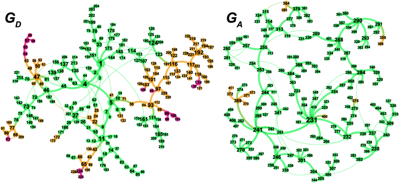
The MC-AFIR and SC-AFIR reaction path searches for dissociative and associative mechanisms gave two reaction path networks, which are shown as graphs GD and GA in Fig. 10. The subscripts ‘D’ and ‘A’ denote dissociative and associative mechanisms, respectively. The former consists of 361 LMs and 344 TSs, while the latter consists of 257 LMs and 257 TSs.To discuss the networks, all LMs and TSs are classified into the following three classes: C1: a ‘reactant’ complex, which has two C(1)–H bonds in the substrate (green in Fig. 10); C2: a ‘hydride’ complex, which is classified as neither a reactant nor a product complex (yellow in Fig. 10); C3: a ‘product’ complex, which has one C(3)–H bond in the substrate (red in Fig. 10). The longest C–H bond distance was set as 1.3 Å.
3.3 Dissociative mechanism (GD)
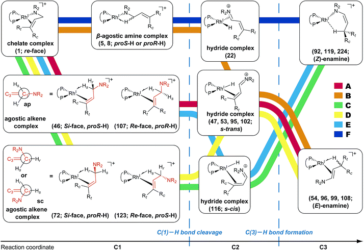
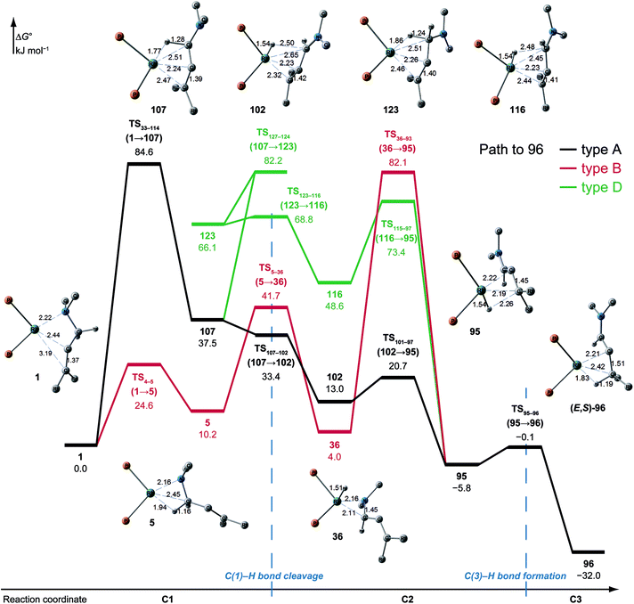
According to the present rules, the chelate complex 1 is the starting point in the dissociative mechanism (Fig. 11). A nitrogen atom and a C![[double bond, length as m-dash]](https://www.rsc.org/images/entities/char_e001.gif) C double bond from the re-face direction are coordinated to a Rh(I) atom in complex 1. All of the paths can be classified into six types (A–F in Fig. 11) by their combinations of intermediates. The paths from complex 1 to the product (C3) are summarised in Table 1.
C double bond from the re-face direction are coordinated to a Rh(I) atom in complex 1. All of the paths can be classified into six types (A–F in Fig. 11) by their combinations of intermediates. The paths from complex 1 to the product (C3) are summarised in Table 1.
| LM (C3) | E/Z | S/R | Possible paths | Path on MST |
|---|---|---|---|---|
| 54 | E | R | A, B | A |
| 92 | Z | R | C | C |
| 96 | E | S | A, B, D | B |
| 99 | E | S | A, B, D | B |
| 108 | E | S | A, B, D | B |
| 119 | Z | S | C, E | E |
| 224 | Z | S | F | F |
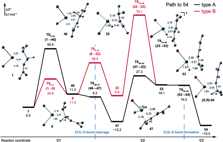
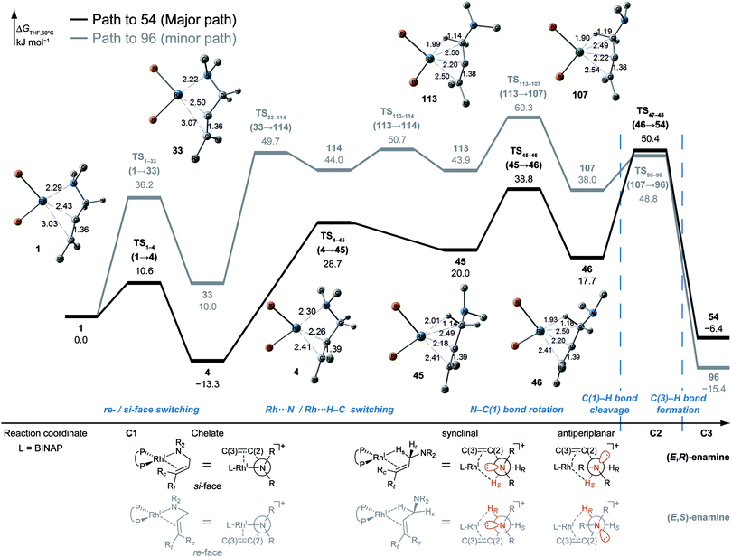
![[double bond, length as m-dash]](https://www.rsc.org/images/entities/char_e001.gif) C-coordinate complex 46, which experiences an agostic interaction between the Rh(I) atom and the HS–C(1) bond. The energy profile is shown in Fig. 12. The Rh-bound H atom (HS) migrates to the Rh(I) atom as a hydride with the assistance of an electron supplied from the N atom; this results in the formation of an iminium ion structure (47). Importantly, the C(1)
C-coordinate complex 46, which experiences an agostic interaction between the Rh(I) atom and the HS–C(1) bond. The energy profile is shown in Fig. 12. The Rh-bound H atom (HS) migrates to the Rh(I) atom as a hydride with the assistance of an electron supplied from the N atom; this results in the formation of an iminium ion structure (47). Importantly, the C(1)![[double bond, length as m-dash]](https://www.rsc.org/images/entities/char_e001.gif) N double bond of the iminium ion moiety is not bound to the Rh(I) atom, in contrast to the η2-coordination in the mechanism proposed by Noyori et al. (IV and VII in Fig. 2). Then, a conformational change through rotation around the π-coordination axis forms another C
N double bond of the iminium ion moiety is not bound to the Rh(I) atom, in contrast to the η2-coordination in the mechanism proposed by Noyori et al. (IV and VII in Fig. 2). Then, a conformational change through rotation around the π-coordination axis forms another C![[double bond, length as m-dash]](https://www.rsc.org/images/entities/char_e001.gif) C-coordination Rh(I) hydride complex 53, which is the rate limiting step of path A to 54 (ΔG = 27.3 kJ mol−1). Finally, the (E,R)-enamine coordinate complex 54 is formed through hydride migration.
C-coordination Rh(I) hydride complex 53, which is the rate limiting step of path A to 54 (ΔG = 27.3 kJ mol−1). Finally, the (E,R)-enamine coordinate complex 54 is formed through hydride migration.
One path to 54 (type B) is consistent with the mechanism of Noyori et al. In this path, the Rh(I)-bound iminium ion IV in Fig. 2 is formed through hydride migration from the N-coordinate Rh(I) complex III. The path to 54 (type B) forms the Rh(I)-bound iminium ion 22 through hydride migration from the N-coordinate Rh(I) complex 8. Then, intramolecular coordination switching occurs (TS23–49 (22 → 53)), when the iminium ion of the substrate is eliminated from the Rh(I) centre and the C![[double bond, length as m-dash]](https://www.rsc.org/images/entities/char_e001.gif) C double bond of the substrate coordinates to the Rh(I) centre to form the C
C double bond of the substrate coordinates to the Rh(I) centre to form the C![[double bond, length as m-dash]](https://www.rsc.org/images/entities/char_e001.gif) C-coordinate Rh(I) hydride complex 53. Because the distance between the iminium ion and the Rh(I) centre is longer than that of the other intermediates, the energy of TS23–49 (22 → 53) is higher (ΔG = 79.1 kJ mol−1) than that of the other LMs and TSs. As a result, the type B path is disadvantageous compared with the type A path.
C-coordinate Rh(I) hydride complex 53. Because the distance between the iminium ion and the Rh(I) centre is longer than that of the other intermediates, the energy of TS23–49 (22 → 53) is higher (ΔG = 79.1 kJ mol−1) than that of the other LMs and TSs. As a result, the type B path is disadvantageous compared with the type A path.
The difference between the paths (type A) can be observed from the chelate complex. The chelate complex 33 (ΔG = 10.0 kJ mol−1), in which the C![[double bond, length as m-dash]](https://www.rsc.org/images/entities/char_e001.gif) C double bond is coordinated to Rh(I) from the re-face, is higher in energy than another chelate complex, 4 (ΔG = −13.3 kJ mol−1), in which the C
C double bond is coordinated to Rh(I) from the re-face, is higher in energy than another chelate complex, 4 (ΔG = −13.3 kJ mol−1), in which the C![[double bond, length as m-dash]](https://www.rsc.org/images/entities/char_e001.gif) C double bond is coordinated from the opposite face. The reactions on both paths A (1 → 46 and 1 → 107) proceed while maintaining the Rh(I)⋯C
C double bond is coordinated from the opposite face. The reactions on both paths A (1 → 46 and 1 → 107) proceed while maintaining the Rh(I)⋯C![[double bond, length as m-dash]](https://www.rsc.org/images/entities/char_e001.gif) C bond and the energy difference. Accordingly, the R/S selectivity of the product depends on the coordination state of the enantiotopic face of the allyl group.
C bond and the energy difference. Accordingly, the R/S selectivity of the product depends on the coordination state of the enantiotopic face of the allyl group.
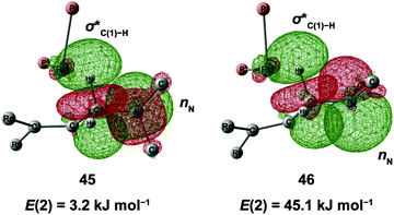
N–C(1) bond rotations (45 → 46 and 113 → 107) occur on the type A path; this is a significantly high energy process. The rotation connects a C![[double bond, length as m-dash]](https://www.rsc.org/images/entities/char_e001.gif) C-coordinate Rh(I) complex (45 or 113) with the synclinal (sc) conformation of the dihedral angle H–C(1)–N–lp (lone pair) to a complex with an antiperiplanar (ap) conformation (46 or 107). The sc conformation must form immediately after the Rh(I)⋯N bond cleavage. In contrast, the ap conformation is advantageous from the viewpoint of the stereoelectronic effects between the non-bonding orbital of the nitrogen (nN) and the C(1)–H antibonding orbital
C-coordinate Rh(I) complex (45 or 113) with the synclinal (sc) conformation of the dihedral angle H–C(1)–N–lp (lone pair) to a complex with an antiperiplanar (ap) conformation (46 or 107). The sc conformation must form immediately after the Rh(I)⋯N bond cleavage. In contrast, the ap conformation is advantageous from the viewpoint of the stereoelectronic effects between the non-bonding orbital of the nitrogen (nN) and the C(1)–H antibonding orbital  . The orbital overlap can be confirmed by NBO analysis, and the strength of the donor–acceptor interaction between the nN and the
  orbitals can be confirmed by the second-order perturbation energy E(2) (Fig. 16). As the donor–acceptor interaction increases in strength (45: E(2) = 3.2 kJ mol−1 → 46: E(2) = 45.1 kJ mol−1), the C(1)–H bond length increases slightly (45: 1.14 Å → 46: 1.18 Å). In other words, the interaction weakens the C(1)–H bond. This factor is important for C(1)–H activation.
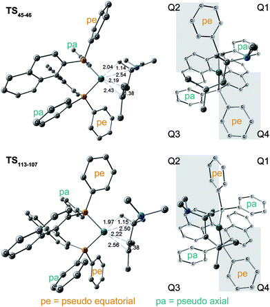
The N–C(1) bond rotation is a more energy-demanding step in the paths from 1 to 46 and from 1 to 107 (Fig. 15). Comparing the respective TSs of the N–C(1) bond rotation, the BINAP ligand at TS45–46 (the si-face) maintains C2-symmetry very well, while that for TS113–107 (the re-face) is largely distorted, especially for two of the pseudo-equatorial phenyl groups (Fig. 17). This is because the dialkylamino group and the methyl group on the C(3) atom in TS113–107 (re-face) occupy the upper left space (second quadrant) and the lower right (fourth quadrant) (Fig. 17), which was originally occupied by the pseudo-equatorial phenyl groups of the BINAP ligand, to avoid steric repulsion between the substrate and the phenyl group; therefore, the BINAP ligand is largely distorted. We performed EDA to investigate the energy difference between TS45–46 and TS113–107 (Table 2). The energy difference (ΔΔE = 19.1 kJ mol−1) between these TSs is consistent with the deformation energy difference (ΔDEF = 16.9 kJ mol−1) and the interaction energy difference (ΔINT = 2.2 kJ mol−1). The contributions of the ΔΔE mainly originate from the DEF (88.9%), and the contribution of INT is small (11.1%). Furthermore, the difference in deformation energy in the allylamine moiety (ΔDEFA = −0.1 kJ mol−1) is negligible, and that of the BINAP–Rh(I) moiety (ΔDEFB = 17.0 kJ mol−1) occupies the majority of the ΔDEF.
| DEF (DEFA, DEFB) | INT | ΔE | ΔG | |
|---|---|---|---|---|
| TS45–46 (si-face) | 52.5 (39.5, 13.0) | −132.9 | 51.6 | 17.7 |
| TS113–107 (re-face) | 69.4 (39.3, 30.0) | −130.7 | 70.7 | 38.0 |
| Δ | 16.9 (−0.1, 17.0) | 2.2 | 19.1 | 21.5 |
3.4 Associative mechanism
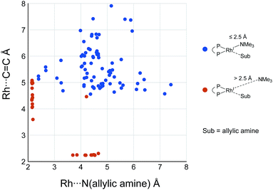
While some product complexes (red vertex in Fig. 10) are present in the network of the dissociative mechanism, there is no product complex in the network of the associative mechanism. To confirm the coordination state of all of the LMs, the Rh(I)–N (allylic amine) distance and the distance between the Rh(I) atom and the centre of the C(2)![[double bond, length as m-dash]](https://www.rsc.org/images/entities/char_e001.gif) C(3) bond are summarised in the scatter plot shown in Fig. 18, in which the LMs are divided into two groups by the Rh(I)–N (TMA) distance. Some C
C(3) bond are summarised in the scatter plot shown in Fig. 18, in which the LMs are divided into two groups by the Rh(I)–N (TMA) distance. Some C![[double bond, length as m-dash]](https://www.rsc.org/images/entities/char_e001.gif) C-coordinate Rh(I) complexes have no TMA coordination (orange plot in Fig. 18); however, no C
C-coordinate Rh(I) complexes have no TMA coordination (orange plot in Fig. 18); however, no C![[double bond, length as m-dash]](https://www.rsc.org/images/entities/char_e001.gif) C-coordinate Rh(I) complex is formed with TMA coordination (blue plot in Fig. 18). This result is different from the allylic mechanism of Ujaque and Espinet et al.18 (to find a C
C-coordinate Rh(I) complex is formed with TMA coordination (blue plot in Fig. 18). This result is different from the allylic mechanism of Ujaque and Espinet et al.18 (to find a C![[double bond, length as m-dash]](https://www.rsc.org/images/entities/char_e001.gif) C-coordinate Rh(I) complex, 647 approximate TSs were searched with the MC-AFIR and SC-AFIR methods for the associative mechanism). In the previous study by Ujaque and Espinet et al., the models that they used to conclude that the associative mechanism and allylic mechanism are favourable were too small (e.g. they used two PH3 molecules as a model of the BINAP ligand). However, BINAP is a bulky ligand; thus, the coordination of the comparably bulky C
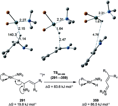
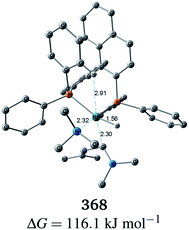
C-coordinate Rh(I) complex, 647 approximate TSs were searched with the MC-AFIR and SC-AFIR methods for the associative mechanism). In the previous study by Ujaque and Espinet et al., the models that they used to conclude that the associative mechanism and allylic mechanism are favourable were too small (e.g. they used two PH3 molecules as a model of the BINAP ligand). However, BINAP is a bulky ligand; thus, the coordination of the comparably bulky C![[double bond, length as m-dash]](https://www.rsc.org/images/entities/char_e001.gif) C bond to the Rh(I) centre is impossible in the associative mechanism. There are eight paths of C(1)–H bond cleavage in the graph GA (231 → 400, 241 → 369, 279 → 376, 291 → 359, 315 → 384, 374 → 369, 379 → 384 and 402 → 376). The most preferred path among the eight paths starts from the N-coordinate Rh(I) complex 291 (Fig. 19). After 291 is formed, a hydride on C(1) is abstracted by the Rh(I) centre, and the complex is separated into the N-hydride-coordinate Rh(I) and iminium ion fragments 359 (Fig. 19). The eight C(1)–H cleavage paths shown above proceed similarly. The hydride complex 368 has the largest coordination number (five-coordinate Rh(III) complex) in the entire network, which is formed from 359 through Rh(I)–C(1) bond formation. 368 has a square pyramidal geometry, as shown in Fig. 20.
C bond to the Rh(I) centre is impossible in the associative mechanism. There are eight paths of C(1)–H bond cleavage in the graph GA (231 → 400, 241 → 369, 279 → 376, 291 → 359, 315 → 384, 374 → 369, 379 → 384 and 402 → 376). The most preferred path among the eight paths starts from the N-coordinate Rh(I) complex 291 (Fig. 19). After 291 is formed, a hydride on C(1) is abstracted by the Rh(I) centre, and the complex is separated into the N-hydride-coordinate Rh(I) and iminium ion fragments 359 (Fig. 19). The eight C(1)–H cleavage paths shown above proceed similarly. The hydride complex 368 has the largest coordination number (five-coordinate Rh(III) complex) in the entire network, which is formed from 359 through Rh(I)–C(1) bond formation. 368 has a square pyramidal geometry, as shown in Fig. 20.
In all of the hydride complexes except for complex 368, the substrate is located far from the Rh(I) centre (see the ESI, Section 2.1†). Because the vacant position of complex 368 is blocked by a phenyl group of the BINAP ligand, the formation of the six-coordinate distorted-octahedral complex proposed by Takaya and Noyori et al.17 and Ujaque and Espinet et al.18 appears to be impossible. Furthermore, the relative free energy of complex 368 (ΔG = 116.1 kJ mol−1) is energetically unstable. Accordingly, the associative mechanisms of Takaya and Noyori et al. and Ujaque and Espinet et al. are unfavorable.
4 Conclusions
We explored the reaction paths of the cationic Rh(I)–BINAP-catalysed isomerisation of allylic amines by employing the MC-AFIR and SC-AFIR methods combined with the ONIOM method; furthermore, we determined the most rational path from the complicated reaction network by employing Prim’s algorithm. We conclude that the associative mechanism is impossible because there is no path leading to the product complex in the associative mechanism; also, the intermediates in the associative mechanism are unstable compared with those in the dissociative mechanism. In the dissociative mechanism, a path to 54 (type A) is the most rational path; it affords the (E,R)-enamine, which is consistent with the experimental results. Some paths afford the (Z)-enamine. However, the path to the (Z)-enamine is an endergonic process; therefore, the (Z)-enamine is not formed. The path to 96 leads to the opposite enantiomer of 54. The C![[double bond, length as m-dash]](https://www.rsc.org/images/entities/char_e001.gif) C-coordinate Rh(I) complexes on the path to 54 (e.g.45: ΔG = 20.0 kJ mol−1) are comparably stable intermediates. In contrast, those on the path to 96 (e.g.113: ΔG = 43.9 kJ mol−1) are higher in energy. The difference arises from the steric repulsion between a pseudo-equatorial phenyl group and a substrate; the phenyl group on the dialkylamino group side is especially distorted. The path to 96 is not preferred because of the instability of the C
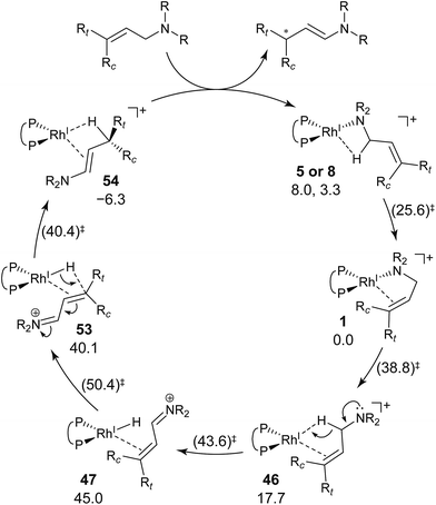
C-coordinate Rh(I) complexes on the path to 54 (e.g.45: ΔG = 20.0 kJ mol−1) are comparably stable intermediates. In contrast, those on the path to 96 (e.g.113: ΔG = 43.9 kJ mol−1) are higher in energy. The difference arises from the steric repulsion between a pseudo-equatorial phenyl group and a substrate; the phenyl group on the dialkylamino group side is especially distorted. The path to 96 is not preferred because of the instability of the C![[double bond, length as m-dash]](https://www.rsc.org/images/entities/char_e001.gif) C-coordinated intermediates. The catalytic cycle is summarised in Fig. 21. The cycle starts from the chelate complex 1 or from the N-coordinate complex 5 or 8. Complex 1 is converted to a C
C-coordinated intermediates. The catalytic cycle is summarised in Fig. 21. The cycle starts from the chelate complex 1 or from the N-coordinate complex 5 or 8. Complex 1 is converted to a C![[double bond, length as m-dash]](https://www.rsc.org/images/entities/char_e001.gif) C-coordinate complex 46, which has an agostic interaction between the Rh(I) atom and the H–C(1) bond. In 46, the C
C-coordinate complex 46, which has an agostic interaction between the Rh(I) atom and the H–C(1) bond. In 46, the C![[double bond, length as m-dash]](https://www.rsc.org/images/entities/char_e001.gif) C double bond is coordinated to the Rh(I) atom from the si-face direction. Then, the hydride ion on the C(1) atom migrates to the Rh(I) atom and the hydride complex 47 is formed, in which the lone pair of the nitrogen atom assists hydride migration. Complex 53 is a conformational isomer of 47. Finally, hydride migration from the Rh(I) atom to the C(3) atom forms the product complex 54 ((E,R)-enamine). After the formation of 54, the catalytic cycle moves to the next cycle through substitution.
C double bond is coordinated to the Rh(I) atom from the si-face direction. Then, the hydride ion on the C(1) atom migrates to the Rh(I) atom and the hydride complex 47 is formed, in which the lone pair of the nitrogen atom assists hydride migration. Complex 53 is a conformational isomer of 47. Finally, hydride migration from the Rh(I) atom to the C(3) atom forms the product complex 54 ((E,R)-enamine). After the formation of 54, the catalytic cycle moves to the next cycle through substitution.
The aim of the present study is to demonstrate the possibility of determining a reaction mechanism without assumption of TSs. We achieved this using the MC-AFIR and SC-AFIR methods. Furthermore, the E/Z and S/R selectivity of the product could be explained. In addition, we demonstrated the usefulness of Prim’s algorithm to find a rational combination of elementary reaction steps. We hope the present study demonstrates the successful application of the AFIR method and Prim’s algorithm.
Acknowledgements
This work was supported by a Grant-in-Aid for Scientific Research on Innovative Areas in “Precisely Designed Catalysts with Customized Scaffolding” (JSPS KAKENHI Grant Number JP15H05801 and JP16H01001) to M. S. and S. M., respectively, and “Stimuli-responsive Chemical Species for the Creation of Functional Molecules (No. 2408)” (JSPS KAKENHI Grant Number JP15H00913 and JP15H00938) to S. M. and K. M., respectively, and JST ACT-C (JPMJCR12YN) to M. S., S. M. and T. T. The generous allotment of computation time from the Research Centre for Computational Science, the National Institutes of Natural Sciences, Japan, is also gratefully acknowledged.References
- A. Miyashita, A. Yasuda, H. Takaya, K. Toriumi, T. Ito, T. Souchi and R. Noyori, J. Am. Chem. Soc., 1980, 102, 7932–7934 CrossRef CAS.
- R. Noyori, M. Ohta, Y. Hsiao, M. Kitamura, T. Ohta and H. Takaya, J. Am. Chem. Soc., 1986, 108, 7117–7119 CrossRef CAS.
- R. Noyori, Angew. Chem., Int. Ed., 2002, 41, 2008–2022 CrossRef CAS PubMed.
- R. Noyori, M. Kitamura and T. Ohkuma, Proc. Natl. Acad. Sci. U. S. A., 2004, 101, 5356–5362 CrossRef CAS PubMed.
- S. Mori, T. Vreven and K. Morokuma, Chem.–Asian J., 2006, 1, 391–403 CrossRef CAS PubMed.
- S. Maeda and K. Ohno, J. Phys. Chem. A, 2007, 111, 13168–13171 CrossRef CAS PubMed.
- S. Maeda and K. Ohno, J. Am. Chem. Soc., 2008, 130, 17228–17229 CrossRef CAS PubMed.
- K. Tani, T. Yamagata, S. Otsuka, S. Akutagawa, H. Kumobayashi, T. Taketomi, H. Takaya, A. Miyashita and R. Noyori, J. Chem. Soc., Chem. Commun., 1982, 600–601 RSC.
- K. Tani, T. Yamagata, S. Akutagawa, H. Kumobayashi, T. Taketomi, H. Takaya, A. Miyashita, R. Noyori and S. Otsuka, J. Am. Chem. Soc., 1984, 106, 5208–5217 CrossRef CAS.
- R. Noyori, Science, 1990, 248, 1194–1199 CAS.
- R. Noyori and H. Takaya, Acc. Chem. Res., 1990, 23, 345–350 CrossRef CAS.
- S. Otsuka and K. Tani, Synthesis, 1991, 665–680 CrossRef CAS.
- R. Noyori, CHEMTECH, 1992, 22, 360 CAS.
- S. Akutagawa and K. Tani, Catalytic Asymmetric Synthesis, Wiley-VCH, Weinheim, 2nd edn, 2000, pp. 145–161 Search PubMed.
- J. F. Hartwig and M. A. Larsen, ACS Cent. Sci., 2016, 2, 281–292 CrossRef CAS PubMed.
- S. Inoue, H. Takaya, K. Tani, S. Otsuka, T. Sato and R. Noyori, J. Am. Chem. Soc., 1990, 112, 4897–4905 CrossRef CAS.
- M. Yamakawa and R. Noyori, Organometallics, 1992, 11, 3167–3169 CrossRef.
- A. Nova, G. Ujaque, A. C. Albéniz and P. Espinet, Chem.–Eur. J., 2008, 14, 3323–3329 CrossRef CAS PubMed.
- Y. Sumiya, Y. Nagahata, T. Komatsuzaki, T. Taketsugu and S. Maeda, J. Phys. Chem. A, 2015, 119, 11641–11649 CrossRef CAS PubMed.
- Y. Sumiya, T. Taketsugu and S. Maeda, J. Comput. Chem., 2017, 2, 101–109 CrossRef PubMed.
- E. Martínez-Núñez, Phys. Chem. Chem. Phys., 2015, 17, 14912–14921 RSC.
- S. Habershon, J. Chem. Theory Comput., 2016, 12, 1786–1798 CrossRef CAS PubMed.
- I. Mitchell, S. Irle and A. J. Page, J. Chem. Phys., 2016, 145, 24105 CrossRef PubMed.
- S. Maeda and K. Morokuma, J. Chem. Phys., 2010, 132, 241102 CrossRef PubMed.
- S. Maeda, S. Komagawa, M. Uchiyama and K. Morokuma, Angew. Chem., Int. Ed., 2011, 50, 644–649 CrossRef CAS PubMed.
- S. Maeda, K. Ohno and K. Morokuma, Phys. Chem. Chem. Phys., 2013, 15, 3683–3701 RSC.
- S. Maeda, T. Taketsugu and K. Morokuma, J. Comput. Chem., 2014, 35, 166–173 CrossRef CAS PubMed.
- M. Hatanaka, S. Maeda and K. Morokuma, J. Chem. Theory Comput., 2013, 9, 2882–2886 CrossRef CAS PubMed.
- R. Uematsu, S. Maeda and T. Taketsugu, Chem.–Asian J., 2014, 9, 305–312 CrossRef CAS PubMed.
- R. Uematsu, E. Yamamoto, S. Maeda, H. Ito and T. Taketsugu, J. Am. Chem. Soc., 2015, 137, 4090–4099 CrossRef CAS PubMed.
- S. Maeda, Y. Harabuchi, Y. Sumiya, M. Takagi, M. Hatanaka, Y. Osada, T. Taketsugu, K. Morokuma and K. Ohno, A developmental version of GRRM program, Hokkaido University, Sapporo, Japan Search PubMed.
- F. Maseras and K. Morokuma, J. Comput. Chem., 1995, 16, 1170–1179 CrossRef CAS.
- S. Humbel, S. Sieber and K. Morokuma, J. Chem. Phys., 1996, 105, 1956 CrossRef.
- T. Matsubara, S. Sieber and K. Morokuma, Int. J. Quantum Chem., 1996, 60, 1101–1109 CrossRef.
- M. Svensson, S. Humbel, R. D. J. Froese, T. Matsubara, S. Sieber and K. Morokuma, J. Phys. Chem., 1996, 100, 19357–19363 CrossRef CAS.
- S. Dapprich, I. Komáromi, K. S. Byun, K. Morokuma and M. J. Frisch, J. Mol. Struct.: THEOCHEM, 1999, 461–462, 1–21 CrossRef CAS.
- T. Vreven and K. Morokuma, J. Comput. Chem., 2000, 21, 1419–1432 CrossRef CAS.
- T. Vreven, K. S. Byun, I. Komáromi, S. Dapprich, J. A. Montgomery Jr, K. Morokuma and M. J. Frisch, J. Chem. Theory Comput., 2006, 2, 815–826 CrossRef CAS PubMed.
- L. W. Chung, W. M. C. Sameera, R. Ramozzi, A. J. Page, M. Hatanaka, G. P. Petrova, T. V. Harris, X. Li, Z. Ke, F. Liu, H.-B. Li, L. Ding and K. Morokuma, Chem. Rev., 2015, 115, 5678–5796 CrossRef CAS PubMed.
- A. K. Rappé, C. J. Casewit, K. S. Colwell, W. A. Goddard III and W. M. Skiff, J. Am. Chem. Soc., 1992, 114, 10024–10035 CrossRef.
- A. D. Becke, J. Chem. Phys., 1993, 98, 5648 CrossRef CAS.
- P. J. Hay and W. R. Wadt, J. Chem. Phys., 1985, 82, 270 CrossRef CAS.
- P. J. Hay and W. R. Wadt, J. Chem. Phys., 1985, 82, 299 CrossRef CAS.
- K. Fukui, Acc. Chem. Res., 1981, 14, 363–368 CrossRef CAS.
- M. J. Frisch, G. W. Trucks, H. B. Schlegel, G. E. Scuseria, M. A. Robb, J. R. Cheeseman, G. Scalmani, V. Barone, B. Mennucci, G. A. Petersson, H. Nakatsuji, M. Caricato, X. Li, H. P. Hratchian, A. F. Izmaylov, J. Bloino, G. Zheng, J. L. Sonnenberg, M. Hada, M. Ehara, K. Toyota, R. Fukuda, J. Hasegawa, M. Ishida, T. Nakajima, Y. Honda, O. Kitao, H. Nakai, T. Vreven, J. A. Montgomery Jr, J. E. Peralta, F. Ogliaro, M. Bearpark, J. J. Heyd, E. Brothers, K. N. Kudin, V. N. Staroverov, R. Kobayashi, J. Normand, K. Raghavachari, A. Rendell, J. C. Burant, S. S. Iyengar, J. Tomasi, M. Cossi, N. Rega, J. M. Millam, M. Klene, J. E. Knox, J. B. Cross, V. Bakken, C. Adamo, J. Jaramillo, R. Gomperts, R. E. Stratmann, O. Yazyev, A. J. Austin, R. Cammi, C. Pomelli, J. W. Ochterski, R. L. Martin, K. Morokuma, V. G. Zakrzewski, G. A. Voth, P. Salvador, J. J. Dannenberg, S. Dapprich, A. D. Daniels, Ö. Farkas, J. B. Foresman, J. V. Ortiz, J. Cioslowski and D. J. Fox, Gaussian 09 Revision D.01, Gaussian Inc., Wallingford CT, 2009 Search PubMed.
- S. Maeda, Y. Harabuchi, M. Takagi, T. Taketsugu and K. Morokuma, Chem. Rec., 2016, 16, 2232–2248 CrossRef CAS PubMed.
- W. M. C. Sameera, S. Maeda and K. Morokuma, Acc. Chem. Res., 2016, 49, 763–773 CrossRef CAS PubMed.
- R. C. Prim, Bell Syst. Tech. J., 1957, 36, 1389–1401 CrossRef.
- M. Bastian, S. Heymann and M. Jacomy, Gephi: An Open Source Software for Exploring and Manipulating Networks, 2009 Search PubMed.
- S. Grimme, J. Antony, S. Ehrlich and H. Krieg, J. Chem. Phys., 2010, 132, 154104 CrossRef PubMed.
- D. Andrae, U. Häußermann, M. Dolg, H. Stoll and H. Preuß, Theor. Chem. Acc., 1990, 77, 123–141 CrossRef CAS.
- M. Dolg, H. Stoll, H. Preuss and R. M. Pitzer, J. Phys. Chem., 1993, 97, 5852–5859 CrossRef CAS.
- F. Weigend and R. Ahlrichs, Phys. Chem. Chem. Phys., 2005, 7, 3297–3305 RSC.
- F. Weigend, Phys. Chem. Chem. Phys., 2006, 8, 1057–1065 RSC.
- J. Tomasi, B. Mennucci and R. Cammi, Chem. Rev., 2005, 105, 2999–3094 CrossRef CAS PubMed.
- S. Miertuš, E. Scrocco and J. Tomasi, Chem. Phys., 1981, 55, 117–129 CrossRef.
- E. Cancès, B. Mennucci and J. Tomasi, J. Chem. Phys., 1997, 107, 3032 CrossRef.
- E. D. Glendening, A. E. Reed, J. E. Carpenter and F. Weinhold, NBO Version 3.1 Search PubMed.
- K. Morokuma, J. Chem. Phys., 1971, 55, 1236 CrossRef CAS.
- K. Kitaura and K. Morokuma, Int. J. Quantum Chem., 1976, 10, 325–340 CrossRef CAS.
- M. Brookhart, M. L. H. Green and G. Parkin, Proc. Natl. Acad. Sci. U. S. A., 2007, 104, 6908–6914 CrossRef CAS PubMed.
Footnote |
| † Electronic supplementary information (ESI) available. See DOI: 10.1039/c7sc00401j |
| This journal is © The Royal Society of Chemistry 2017 |

