
 Open Access Article
 This Open Access Article is licensed under a Creative Commons Attribution-Non Commercial 3.0 Unported Licence
The marriage of AIE and interface engineering: convenient synthesis and enhanced photovoltaic performance†
Can
Wang‡
a,
Zhiyang
Liu‡
bc,
Mengshu
Li
a,
Yujun
Xie
a,
Bingshi
Li
d,
Shuo
Wang
d,
Shan
Xue
d,
Qian
Peng
e,
Bin
Chen
f,
Zujin
Zhao
 f,
Qianqian
Li
a,
Ziyi
Ge
*bc and
Zhen
Li
*a
f,
Qianqian
Li
a,
Ziyi
Ge
*bc and
Zhen
Li
*a
aDepartment of Chemistry, Wuhan University, Wuhan 430072, China. E-mail: lizhen@whu.edu.cn; lichemlab@163.com
bNingbo Institute of Materials Technology and Engineering, Chinese Academy of Sciences, Ningbo 315201, China. E-mail: geziyi@nimte.ac.cn
cUniversity of Chinese Academy of Sciences, Beijing, 100049, China
dDepartment of Chemistry and Chemical Engineering, Shenzhen University, Shenzhen 518060, China
eBeijing National Laboratory for Molecular Science (BNLMS), Institute of Chemistry Chinese Academy of Sciences, Beijing 100190, China
fState Key Laboratory of Luminescent Materials and Devices, South China University of Technology, Guangzhou 510640, China
First published on 23rd February 2017
Abstract
As a promising option out of all of the well-recognized candidates that have been developed to solve the coming energy crisis, polymer solar cells (PSCs) are a kind of competitive clean energy source. However, as a convenient and efficient method to improve the efficiency of PSCs, the inherent mechanism of the interfacial modification was still not so clear, and interfacial materials constructed with new units were limited to a large degree. Here we present a new kind of interfacial material consisting of AIE units for the first time, with an efficiency of 8.94% being achieved by inserting TPE-2 as a cathode interlayer. This is a relatively high PCE for PC71BM:PTB7-based conventional PSCs with a single-junction structure. Different measurements, including TEM, AFM, SEM, GIXRD, UPS, SKPM, and SCLC, were conducted to investigate the properties in detail. All of the obtained experimental results confirmed the advantages of the utilization of new interfacial materials with AIE characteristics in polymer solar cells, thus providing an additional choice to develop new organic cathode interfacial layers with high performances.
BHJ PSCs, with the full name of bulk heterojunction polymer solar cells, in recent decades have received increasing interest for their use in renewable energy sources, due to their unique advantages including ease of fabrication, capability for large areas, flexibility, low-cost room-temperature solution process, and their light weight and continuously improving power conversion efficiencies (PCEs).1 Typically, a photoactive layer, composed of a fullerene derivative as the acceptor and a conjugated polymer as the donor, is sandwiched between a cathode and anode with their corresponding interlayers. The efficiency of the PSCs could be further improved through interfacial optimization, including decreased contact resistance, better electronic energy level alignment and more effective electron collection and transport, etc.2 Thanks to the enthusiasm of scientists, different approaches for interfacial modification have been successfully utilized to improve PCEs, including the insertion of transporting layers (electron or hole),3 and the use of solvent treatments,4 surface plasmon polaritons5 and nanoimprinting.6 Considering the practical aspects of commercialization and potential roll-to-roll fabrication techniques,7 water/alcohol soluble organic cathode interfacial layers (CILs) display great advantages over conventional inorganic metal salts (e.g. LiF, Cs2CO3, CsF, etc.), mainly due to the convenient spin-coating process which is required for CILs instead of the vacuum deposition that is required for the latter.8
Mainly, the reported water/alcohol soluble CILs could be divided into two types: π-conjugated molecules and non-conjugated ones, both including polymers and small molecules. As for the π-conjugated CILs, most of them are composed of a π conjugated backbone (generally consisting of fluorene units) and surfactant-like side groups (such as amine, ammonium, phosphate, sulfonic, and zwitterionic groups),9 as shown in Chart S1.† In 2012, Cao and co-workers reported that by using PFN as the CIL, polymer solar cells with an inverted structure (i-PSCs) gave a PCE of 9.15%,10 and the efficiency was further improved to 10.61% in 2015.11 In 2016, Peng reported a set of CILs constructed out of triphenylamine and fluorene units, and an efficiency exceeding 10% was obtained in polymer solar cells with a normal conventional structure (c-PSCs) modified with TFB (Chart 1).12 Almost at the same time, the development of non-conjugated CILs constructed out of nonaromatic units also attracted much attention.13 In 2012, Kippelen and coworkers reported a series of polymers constructed out of aliphatic amines, like PEIE and PEI (Chart S1†), which exhibited good performance once being utilized as surface modifiers in the PSCs.14 Recently, we developed a non-conjugated electrolyte (MSAPBS, Chart 1)15 for c-PSCs with PCEs over 10% and another two non-conjugated electrolytes (DSAPS and DSABS, Chart S1†)16 with PCEs exceeding 9.6%, proving that non-conjugated electrolytes can also implement an ohmic contact for optimal photogenerated electron collection and transport in the device. Then, how about the role of the conjugated blocks in CILs? Also, regardless of the continuous improvement of the PCEs by the insertion of CILs, the origin of the improvement in the PCEs derived from the CILs is still not clear enough. Moreover, besides the dominating CILs constructed with a fluorene unit (a relatively big planar aromatic ring), there are limited examples of other π-conjugated molecules being reported. Therefore, more CIL examples with different constructing units should be explored, in order to provide an additional opportunity to get a better understanding of the working mechanism of CILs.
 | ||
| Chart 1 The structure of the representative conjugated CIL and that of the non-conjugated one for highly efficient PSCs. | ||
Recently, aggregation induced emission (AIE), receiving growing attention from various fields of science, has demonstrated promising potential applications in LEDs, sensors, etc.17 In most AIE luminogens, their typical characteristic is a highly twisted conformation, which avoids the possibility of π–π stacking and the derived effect of aggregation-caused quenching in the aggregation state. As mentioned above, the use of both conjugated and non-conjugated CILs in devices, with and without π–π stacking, respectively, could dramatically enhance the corresponding performances, even without an understanding of the inherent mechanism. Thus, the marriage of AIEgens with CILs might provide another kind of water/alcohol soluble CIL, which contains π-conjugated aromatic rings just like the reported conjugated CILs but also possesses twisted non-planar conformation. Generally, the π-conjugated backbone is beneficial for conductivity which is essential for achieving a high device performance,18 meanwhile, it might also give rise to the π–π stacking problems in the solid state which would have an adverse effect on the device performance. However, the twisted non-planar conformation of the AIEgens could effectively eliminate this problem, and the conjugation degree is much lower than those in conventional π-conjugated molecules, which are similar to the non-conjugated CILs to some extent. That is, they are similar to both conjugated and non-conjugated CILs in some ways, but much different to them in other ways. Thus, perhaps, this kind of AIE-based CIL could provide some new insights. However, despite the wide use of AIE luminogens in biosensors, OLEDs and hole transporting materials in perovskite solar cells,19 attempts at applying CILs in PSCs have not been tried and reported.
In this paper, the first example of an AIE-based CIL was synthesized by introducing a 3-(trimethylammonio)propane-1-sulfonate chain with immobile counter ions to a TPE (tetraphenylethylene) unit, the famous AIE luminogen. The targets, water/alcohol soluble TPE-1 and TPE-2, were successfully applied to PC71BM:PTB7-based conventional PSCs as CILs between the aluminium electrode and the active layer. Consequently, thanks to the presence of AIE-active TPE-1 and TPE-2, the short-circuit current (abbreviated as Jsc), open-circuit voltage (abbreviated as Voc), and fill factor (abbreviated as FF) were dramatically improved, leading to a much enlarged PCE. Specifically, by introducing TPE-2 as the CIL, the PCE was enhanced from 3.89% (bare Al cathode) to 8.94% (∼2.3 times higher), with an improvement from 7.31% (Ca/Al cathode) to 8.94% (+22.3% relative enhancement), which is a relatively high efficiency for PC71BM:PTB7-based conventional PSCs and confirms that TPE derivatives could be a new kind of high-efficiency CIL.
The energy levels of TPE-1 and TPE-2 were measured using cyclic voltammetry. The oxidation potential values for TPE-1 and TPE-2 were observed as 0.84 and 1.02 eV, respectively (Fig. S2†). The HOMO energy levels of TPE-1 and TPE-2 were found to respectively be −5.20 and −5.38 eV, in reference to that of Fc/Fc+, the generally used internal standard value (4.80 eV). The LUMO energy levels of TPE-1 and TPE-2 were also estimated to be −2.80 eV and −2.77 eV, respectively. The electrochemical band gaps (ECVg) of TPE-1 and TPE-2 were thus calculated to be 2.40 and 2.61 eV (Table S1†). Clearly, compared to the data of TPE-1, the introduction of more electron-withdrawing zwitterionic groups to the TPE unit induced a lower HOMO level for TPE-2, which would be beneficial for the electron-injection/-collection properties and for blocking the hole, concurrently.20
To evaluate the performance of TPE-1 and TPE-2 when serving as interlayers, conventional devices based on PC71BM:PTB7 (Fig. 1b) were fabricated with a structure of ITO/PSS:PEDOT/PC71BM:PTB7/interlayer/aluminum. As controlled examples, devices modified with the well-known PFN and Ca interlayers were fabricated under the same conditions. The device configuration is shown in Fig. 1a. The CIL films of TPE-1 and TPE-2 on the active layers were prepared by spin-coating their methanol/acetic acid mixture solution (1 mg mL−1). The thickness of the interlayer was controlled by increasing the spin-coating speed from 2000 to 5000 rpm, to maximize the performance. The J–V curves of the devices with a tunable spin speed are presented in Fig. S3 and S4,† while the device parameters are listed in Tables S2 and S3†. The changing trend of the PCE with the spin speed was exactly the same. By increasing the speed from 2000 to 4000 rpm, the PCE was continuously improved and would be decreased when the spin speed reached 5000 rpm. At the speed of 4000 rpm, the devices achieved the best PCEs of 8.94% for TPE-2 (with Jsc = 16.86 mA cm−2, Voc = 0.76 V, and FF = 0.697), and 8.27% for TPE-1 (with Jsc = 16.02 mA cm−2, Voc = 0.76 V, and FF = 0.681) (Fig. 2a and b and Table 1). Clearly, compared to the PCEs of the other devices (3.89–8.33%), the device modified with a TPE-2 interlayer displayed the highest efficiency of 8.94%, confirming its promising potential once utilized as a CIL. In comparison with the control device without an interlayer (3.89%), the Voc, Jsc, and FF values of the TPE-2-based devices are dramatically improved from 0.55 V to 0.76 V, from 15.45 mA cm−2 to 16.86 mA cm−2, and from 45.51% to 69.70%, respectively. The Ca/aluminum control device displayed an efficiency of 7.31% (with Voc = 0.73 V, FF = 0.6493, and Jsc = 15.32 mA cm−2), a similar result to that reported in the literature.1f When Ca was replaced with the TPE-2 interlayer, the PCE was largely improved by 22.3% (8.94% versus 7.31%), and by 13.1% for TPE-1 (8.27% versus 7.31%). Even compared to the device with a PFN interlayer (PCE = 8.33%), TPE-2 exhibited a better performance with an enhancement both in FF and Jsc.
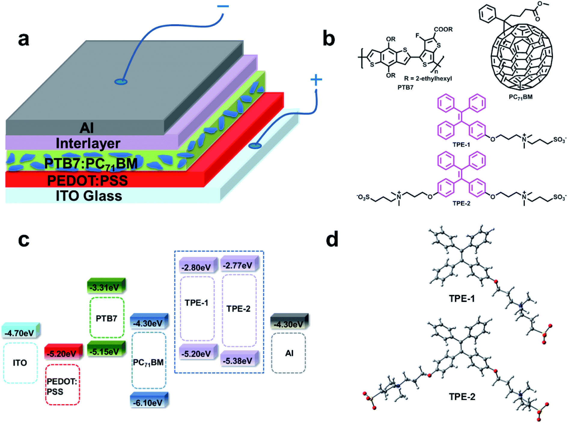 | ||
| Fig. 1 (a) The device architecture. (b) Structures of the TPE derivative interlayers, PC71BM and PTB7. (c) Energy level diagram. (d) Optimized structures of TPE-1 and TPE-2. | ||
 | ||
| Fig. 2 (a) J–V curves of the devices with different interlayer treatments under an illumination of 100 mW cm−2 and AM 1.5 G. (b) J–V curves of the devices in the dark. (c) Emission decay of TPE-1 and TPE-2 in the solid state. The inset photos depict their emission images when in a solid powder form. (d) UPS spectra of the aluminum films with different interlayer treatments. The diagram inserted depicts the status of the energy level in the PSCs that is vertically segregating on the active layer surface. (e) J–V curves and the configurations of the electron-only devices with different interlayer treatments. (f) J–V curves and the configurations of the hole-only devices with different interlayer treatments. | ||
| Interlayer | V oc [V] | J sc [mA cm−2] | FF [%] | PCE [%] best (avg) | Active layer thickness (nm) | R s [Ω cm2] | R sh [kΩ cm2] |
|---|---|---|---|---|---|---|---|
| a (avg) represents the average values of 20 devices. | |||||||
| None | 0.55 | 15.45 | 45.51 | 3.89 (3.80 ± 0.09) | 110 | 14.59 | 0.39 |
| MeOH/Al | 0.76 | 15.62 | 65.56 | 7.83 (7.76 ± 0.07) | 107 | 6.59 | 0.59 |
| Ca/Al | 0.73 | 15.32 | 64.93 | 7.31 (7.21 ± 0.10) | 108 | 4.67 | 0.43 |
| PFN/Al | 0.75 | 16.05 | 68.86 | 8.33 (8.20 ± 0.13) | 105 | 3.27 | 0.37 |
| TPE-1/Al | 0.76 | 16.02 | 68.08 | 8.27 (8.17 ± 0.10) | 106 | 6.08 | 0.83 |
| TPE-2/Al | 0.76 | 16.86 | 69.70 | 8.94 (8.85 ± 0.09) | 107 | 5.36 | 9.05 |
Previous work had proven that the methanol treatment could significantly improve the Voc and FF of the bare Al devices, which should be ascribed to an increase in the built-in voltage across the device as a result of the passivated traps on the surface and a corresponding increased density of charge on the surface.21 Since the solvent used during the device fabrication for TPE-1 and TPE-2 contained methanol, for good comparison, the devices with the bare Al cathode were also fabricated using methanol to verify the effects of methanol treatment. As shown in Table 1, similar to other reported works,12,16 the methanol treatment could significantly improve the Voc and FF (from 0.55 V to 0.76 V, and from 45.5% to 65.56%) of the bare Al devices, and almost retain the Jsc (15.45 versus 15.62 mA cm−2), achieving an enhanced PCE of 7.83%, which is still lower than those of the TPE-1 and TPE-2 based devices (8.27% and 8.94%, respectively). Thus, subtracting the possible influence on the Voc derived from methanol in the TPE-1/TPE-2 solution, the corresponding improvement in the Jsc should be the main reason for the higher PCEs of the TPE-1 and TPE-2 based devices, possibly due to the formation of a net dipole at the electrode interface of the zwitterionic modified TPE derivatives, which is beneficial for charge extraction and for the suppression of recombination at the interface.22
In order to check the surface potential after inserting the CILs, SKPM, with the full name of scanning Kelvin probe microscopy, was employed to study the interfacial dipole. The SPD, with the full name of surface potential difference, was collected and an average was taken from the tip and top films (0.5 mm × 0.5 mm) of the active layer. As shown in Fig. S5,† the SPD between the PC71BM:PTB7 films with and without a TPE-2 layer is ∼0.26 eV, while being ∼0.24 eV for PFN and ∼0.23 eV for TPE-1, respectively. These results indicated that the insertion of an interfacial layer could induce an effective reduction in the Schottky barrier and provide a better charge extraction at the interface. Also, the SPD of the PC71BM:PTB7 film modified with a TPE-2 layer is larger than that of a film with PFN, coinciding with the better device performance of TPE-2 and disclosing its good interfacial modification ability. However, the SPD of PC71BM:PTB7 with methanol treatment exhibited the most positive value (∼0.28 eV), confirming the conclusion that the methanol solvent treatment is the dominant factor for the improvement of the Voc. This also explained that the large enhancement in the Voc was realized by methanol treatment and nearly no improvement in the Voc was observed with the CILs deposited in methanol. So, compared to the control device, the enhancement of the Jsc in the devices modified with TPE-1 or TPE-2 suggested that the charge extraction and transport process were optimized.23 As demonstrated by the J–V characteristics of the devices in the dark (Fig. 2b), the devices modified with the TPE-2 layer displayed the smallest reverse leakage current in comparison with the others, coinciding with its highest Jsc value. The EQE, with the full name of external quantum efficiency, spectra also verified this result and the experimental Jsc values agreed well with those calculated from the incident photo-to-electron conversion efficiency (IPCE) measurement (within 5% error) in the range of 300–800 nm (Fig. S6†).
To gain further insights into the effect of the interlayer structure on the device performance, a space charge limited current (abbreviated as SCLC) measurement was used to investigate the ability of charge transport. The device configurations and corresponding curves are depicted in Fig. 2e and f. The J–V curve was fit using the Mott–Gurney law, J = 9εrε0μV2/8L3, where εrε0 is the dielectric permittivity of the active layer, μ is the mobility, V is the effective voltage, and L is the thickness of the active layer.24 As shown in Table S4,† both the hole and electron mobility of the devices modified with TPE-1/TPE-2 were significantly improved, compared to the control devices with bare aluminum with/without methanol treatment. It can be seen that the TPE-2 based devices exhibited the highest and more balanced hole and electron mobility values of 4.39 × 10⁻⁴ cm2 V−1 s−1 and 1.63 × 10⁻³ cm2 V−1 s−1, which provide a consistent improvement in the Jsc. These results confirmed that the charge transport barrier at the interface between the active layer and electrode was decreased significantly and the charge recombination was suppressed effectively.
Besides the higher mobilities, the TPE-1 and TPE-2 based devices also possess relatively higher FF values (Table 1), which actually stem from their ohmic contact between the active layer and electrode. The contact resistance could be further proven by Rsh and Rs, with the full names of shunt resistance and series resistance, respectively.25 A relatively lower Rs and/or relatively higher Rsh are required for a high FF value. As shown in Table 1, after inserting the CILs, all of the devices exhibited a significant decrease in the Rs compared to the bare Al device. Among them, TPE-2 demonstrated a similar Rs value to that of PFN (5.36 versus 5.02 Ω cm2). Moreover, the TPE-2 based device exhibited the highest Rsh (9.05 kΩ cm2) with an order of magnitude increase compared to the PFN based device. These results suggested that the TPE-2 based devices possessed the ideal ohmic contact, with an obvious enhancement in the Jsc and FF.
To gain a further in-depth knowledge of the possible relationships between the modification properties and structures, we used classical B3LYP density functional theory to do some calculations for the conformation of TPE-1 and TPE-2 at the level of 6-31G(d,p) after optimizing their structures (Fig. 1d). As displayed in Fig. S7,† both of their HOMOs were delocalized over the TPE moiety while the LUMO was located around the SO3− group. The calculated dipole moment of TPE-1 is 24.6 D, while that of TPE-2 is as large as 35.9 D. Theoretically, strong interactions with the aluminium electrode would be expected to exist and a substantially interfaced dipole would be formed, along with a decrease in the work function and interfacial energy barrier, thus resulting in an improvement in the device performance.
To get more information with regards to the interfacial changes after being coated with a CIL, the surface polarity on the surface of the aluminum film was investigated using water contact angle measurements. An aluminum film on ITO glass was prepared by vacuum deposition. As displayed in Fig. 3d, a contact angle (60.6°) was observed for the bare aluminum film, suggesting that the surface was slightly hydrophilic. However, when TPE-1 or TPE-2 was spin-coated onto the Al film, the surface became extremely hydrophilic and the contact angle was reduced to 7.6° and 20.6°, respectively, indicating the formation of net dipoles on the surface, which should be attributed to the polar zwitterion side chain groups.26
 | ||
| Fig. 3 (a) AFM (5 × 5 μm) images of the TPE-1 and TPE-2 films. (b) SEM images of the TPE-1 and TPE-2 films. (c) TEM images of the micro-particles of TPE-1 and TPE-2. (d) Contact angles of the aluminum films in the presence/absence of the TPE-1 or TPE-2 film. (e) GIXRD pattern of the TPE-1 and TPE-2 films on a silicon substrate (out-of-plane). (f) Abridged general view of the possible aggregate state of TPE-1 and TPE-2 in the film state. | ||
All of the above experimental results confirm that the addition of TPE-1 and TPE-2 induces many changes in the interfacial behavior, directly leading to the much enhanced photovoltaic performances. Actually, as reported in the literature, variable measurements had been applied to investigate the surface and interface electronic structures and the involved charge transport process, such as UPS analysis, LE-UPS and PYS (with the full name of low-energy ultraviolet photoelectron spectroscopy and photoelectron yield spectroscopy), and LEIPS, with the full name of low energy inverse photoemission spectroscopy.27 With the aim of investigating the energy level alignments after inserting the CILs, UPS analysis was undertaken to study the possible WF changes. As shown in Fig. 2d, the WF of the Al electrode was −4.30 eV. After being modified with a thin layer of TPE-1 or TPE-2, the WFs of the Al electrodes were changed to −4.22 and −4.20 eV, respectively. The decrease in the WF indicated the formation of interfacial dipoles, which should be attributed to the strong interactions between the CIL and Al electrode. The TPE-2 modified Al electrode possessed a larger Δ value of 0.10 eV rather than that of TPE-1 (0.08 eV), which would offer an energy alignment that is much better suited to the PC71BM LUMO, thus resulting in an improvement in the FF by reducing the recombination and charge transport barrier.
Based on these careful analyses and discussions above, the high performance of the devices modified with TPE-1/TPE-2 should be ascribed to the contribution of the interfacial layer of the introduced TPE-1 or TPE-2 to the improvement of the Jsc and FF. AFM was used to investigate the surface morphology changes of the PC71BM:PTB7 films, after being spin-coated with TPE-1 or TPE-2. As shown in Fig. S8,† compared to that of the pristine PC71BM:PTB7 film, nearly no changes in the morphology were observed after modification with TPE-1 or TPE-2, with a surface root mean square (RMS) roughness of 1.44 nm (TPE-1) and 1.46 nm (TPE-2) vs. 1.46 nm. Both of the modified surfaces remain homogeneous without reconstruction. The influence of the TPE-1/TPE-2 interlayer on the light absorption of the active layer was also studied carefully. As shown in Fig. S9,† in comparison to that of the pristine PC71BM:PTB7 blend films, there are, in the UV-visible absorption spectra, no obvious changes after being modified with TPE-1/TPE-2, suggesting that the interlayer did not reduce the sunlight absorption and transmission in the device.
As confirmed by all of the device parameters, TPE-2 demonstrated a better performance over TPE-1 as a CIL in PC71BM:PTB7-based PSCs, with an apparently higher Jsc, FF and Rsh, as well as lower Rs. Compared to TPE-1, TPE-2 was modified with two zwitterionic chain groups, which significantly changed its optical and physical properties and affected its performance while acting as a CIL. Thus, more detailed information of TPE-1 and TPE-2 should be carefully obtained, in order to investigate the relationship between the structure and device performance.
After the introduction of either one (TPE-1) or two (TPE-2) zwitterionic groups to the tetraphenylethene (TPE) unit, the solubility of TPE-1 and TPE-2 increased distinctly in a hydrophilic solvent such as methanol. Their photophysical properties are summarized in Table S1† and their absorption spectra in methanol are provided in Fig. S1.† The absorption spectra of TPE-2 and TPE-1 in the thin film and nanoaggregate state were measured too. Compared to the results in solution, the absorption spectrum exhibited an obviously broader and bathochromic shift (from 310 nm to 329 nm) for the nanoaggregates of TPE-1, while no obvious difference was observed for TPE-2. However, the spectrum of TPE-2 in the thin film showed a significantly broader and bathochromic shift (33 nm), while TPE-1 displayed a relatively broader absorption spectrum without an obvious peak shift. Based on these differences in the absorption spectra in the solution, nanoaggregate and thin film states, we could conclude that the molecular arrangements of TPE-1 and TPE-2 in the nanoparticles and thin films should be totally different.
Generally, the emission behavior of the fluorophores was affected badly by their molecular arrangement in the aggregated state. As displayed in Fig. 2c, both TPE-1 and TPE-2 emitted intense blue fluorescence in the aggregated state (ΦF,s = 37% for TPE-1 and ΦF,s = 25% for TPE-2) due to their AIE feature, as confirmed by the AIE titration results (Fig. S10†). As shown in Table S1 and Fig. S11,† the photoluminescence (PL) peaks for TPE-2 and TPE-1 are at 443 and 429 nm, respectively.
Interestingly, there are no obvious changes in the PL spectrum of the thin film compared to that of the nanoparticles for TPE-2, while a distinct broader and red-shifted emission (from 443 nm to 483 nm) was observed for the TPE-1 thin film. As is well known, the twisted propeller-shaped molecular conformation of TPE could effectively prevent the π–π interaction or possible formation of aggregates in the form of H or J in the solid state. So the distinct change in the emission behavior should be attributed to their different molecular arrangements in the films. Combined with the absorption spectra discussed above, it was interesting to find out that the Stokes shift of the TPE-2 film was only 85 nm, almost half of that of the TPE-1 film (165 nm), confirming again that TPE-1 and TPE-2 should possess totally different arrangement patterns in the film state.
To gain a visual cognition of the films, the morphology of the TPE-1 and TPE-2 films was investigated using an inverted fluorescence microscope in bright field and dark field, being excited with UV light. As shown in Fig. S12,† the film of TPE-2 exhibited a much more uniform surface compared to that of TPE-1. Furthermore, a deeper insight into the film’s morphology was conducted using AFM (Fig. 3a), in which the TPE-2 film exhibited a more distinct multilayer packing pattern compared to that of TPE-1. The details of the surfaces were further investigated using scanning electron microscopy (SEM, Fig. 3b). The film of TPE-1 exhibited a relatively rough surface, while TPE-2 exhibited a much more smooth surface. The differences in the film morphology should be associated with their different self-assembly properties and packing patterns in the aggregation state. To confirm this conjecture, a TEM (transmission electron microscopy) measurement was conducted, and the TEM images (Fig. 3c) suggest that TPE-1 possessed a random aggregation morphology, whereas the morphology for TPE-2 was quite uniformly structured with square edges in the aggregation state. Furthermore, distinct multilayer structures of TPE-2 were observed in higher multiples, indicating that the existence of intermolecular interactions derived from the charges (negative and positive) of the symmetric zwitterionic chains of TPE-2 endows the ability to form a compact and uniform deposit in the aggregation state or in the thin film state.
To get a deeper insight into the molecular packing pattern and surface morphology of the interlayer, GIXRD, with the full name of grazing incident X-ray diffraction, was further utilized to investigate the thin films. As shown in Fig. 3e, the out-of plane pattern for both of the TPE-1 and TPE-2 thin films displayed a high intensity (100) diffraction peak. However, no obvious multi-diffraction peaks for TPE-1 were observed, whereas distinct diffraction peaks assigned to an a-axis (h00) direction for TPE-2 were apparent, corresponding to the lamellar structure monitored by TEM and AFM in its aggregation state. The first diffraction peaks (100) appear at 2θ = 2.53 and 4.34° for TPE-1 and TPE-2, with interlayer distances of 20.07 Å and 35.31 Å, respectively. These results demonstrated that the thin film of TPE-2 takes a predominantly well-organized stacking structure along the vertical orientation, which is well-known to achieve a high carrier mobility28 because of the intermolecular interactions parallel to the direction of the channel current flow in the PSC devices.29 Thus, the increase of Jsc of TPE-2 compared to that of TPE-1 should be ascribed to the higher electron transporting ability and lower contact resistance, mainly due to its compact and well-organized lamellar structure.
Based on the results discussed above, we could propose a possible molecular arrangement model of TPE-1 and TPE-2 in the thin film state (Fig. 3f). TPE-1 possesses one hydrophobic aromatic group (TPE unit) and a hydrophilic zwitterionic chain. The molecules tend to form an aggregated conformation with an inner aromatic core and an outer zwitterionic chain, which is random because of the electrostatic repulsion on the surface of the microaggregates. On the contrary, after the introduction of two zwitterionic side chains to the TPE unit, TPE-2 could form an orderly aggregated structure due to the electrostatic attraction of the zwitterionic groups in the adjacent molecules. The well-organized structure induced the lamellar stacking pattern of TPE-2 along the vertical orientation, which is beneficial for electron transporting, resulting in a large enhancement in the Jsc and FF.
In summary, by introducing a zwitterionic group to the TPE unit, AIE CILs were successfully developed as cathode interlayers in PSCs for the first time. A PCE as high as 8.94% was obtained when the device was modified with TPE-2, which is a relatively high efficiency for conventional PSCs based on a PC71BM:PTB7 blend, with the single-junction structure. Careful investigation demonstrated that, thanks to the changes in the surface potential derived from the formed dipole and the enhanced mobility, the introduction of TPE-1 and TPE-2 could contribute to the improvement of the Jsc and FF of the corresponding PSCs, directly leading to their high PCE values. Also, the different morphology of the interfacial layer could affect the device performance, as demonstrated by TPE-2 based PSCs in comparison with those of TPE-1, showing the influence of the different number of zwitterionic chains. In comparison with the analogues without the TPE moieties reported by us previously,15,16 there are many different properties that can influence the corresponding devices, especially the absorption capabilities of the active layers and the morphology of the interfacial layers, which demonstrate the unique properties of AIE CILs to some degree. Thus, our findings possibly open up a new avenue for surface modification to achieve high photovoltaic performances.
Acknowledgements
The National Natural Science Foundation of China (No. 21325416 and 51573140), National Fundamental Key Research Program (2013CB834701) and Ningbo Municipal Science and Technology Innovative Research Team (2015B11002, 2016B10005) were appreciated.References
- (a) G. Yu, J. Gao, J. C. Hummelen, F. Wudl and A. J. Heeger, Science, 1995, 270, 1789–1791 CAS; (b) Y. Yang, W. Chen, L. T. Dou, W. H. Chang, H. S. Duan, B. Bob, G. Li and Y. Yang, Nat. Photonics, 2015, 9, 190–198 CrossRef CAS; (c) G. Li, V. Shrotriya, J. S. Huang, Y. Yao, T. Moriarty, K. Emery and Y. Yang, Nat. Mater., 2005, 4, 864–868 CrossRef CAS; (d) J. Y. Kim, K. Lee, N. E. Coates, D. Moses, T. Q. Nguyen, M. Dante and A. J. Heeger, Science, 2007, 317, 222–225 CrossRef CAS PubMed; (e) M. Graetzel, R. A. J. Janssen, D. B. Mitzi and E. H. Sargent, Nature, 2012, 488, 304–312 CrossRef CAS PubMed; (f) S. Q. Zhang, L. Ye and J. H. Hou, Adv. Energy Mater., 2016, 1502529 CrossRef; (g) J. B. Zhao, Y. K. Li, G. F. Yang, K. Jiang, H. R. Lin, H. Ade, W. Ma and H. Yan, Nat. Energy, 2016, 1, 15027 CrossRef CAS; (h) H. W. Hu, K. Jiang, G. F. Yang, J. Liu, Z. K. Li, H. R. Lin, Y. H. Liu, J. B. Zhao, J. Zhang, F. Huang, Y. Q. Qu, W. Ma and H. Yan, J. Am. Chem. Soc., 2015, 137, 14149–14157 CrossRef CAS PubMed; (i) J. B. You, L. T. Dou, K. Yoshimura, T. Kato, K. Ohya, T. Moriarty, K. Emery, C. C. Chen, J. Gao, G. Li and Y. Yang, Nat. Commun., 2013, 4, 1446 CrossRef PubMed; (j) C. Liu, C. Yi, K. Wang, Y. L. Yang, R. S. Bhatta, M. Tsige, S. Y. Xiao and X. Gong, ACS Appl. Mater. Interfaces, 2015, 7, 4928–4935 CrossRef CAS PubMed.
- (a) Z. G. Yin, J. J. Wei and Q. D. Zheng, Adv. Sci., 2016, 1500362 CrossRef PubMed; (b) K. Wang, C. Liu, T. Y. Meng, C. Yi and X. Gong, Chem. Soc. Rev., 2016, 45, 2937–2975 RSC; (c) S. H. Park, A. Roy, S. Beaupre, S. Cho, N. Coates, J. S. Moon, D. Moses, M. Leclerc, K. Lee and A. J. Heeger, Nat. Photonics, 2009, 3, 297–302 CrossRef CAS.
- J. Wang, F. J. Zhang, L. L. Li, Q. S. An, J. Zhang, W. H. Tang and F. Teng, Sol. Energy Mater. Sol. Cells, 2014, 130, 15–19 CrossRef CAS.
- J. H. Seo, A. Gutacker, Y. M. Sun, H. B. Wu, F. Huang, Y. Cao, U. Scherf, A. J. Heeger and G. C. Bazan, J. Am. Chem. Soc., 2011, 133, 8416–8419 CrossRef CAS PubMed.
- H. A. Atwater and A. Polman, Nat. Mater., 2010, 9, 205–213 CrossRef CAS PubMed.
- X. M. He, F. Gao, G. L. Tu, D. Hasko, S. Huttner, U. Steiner, N. C. Greenham, R. H. Friend and W. T. S. Huck, Nano Lett., 2010, 10, 1302–1307 CrossRef CAS PubMed.
- R. Sondergaard, M. Hosel, D. Angmo, T. T. Larsen-Olsen and F. C. Krebs, Mater. Today, 2012, 15, 36–49 CrossRef CAS.
- (a) Z. C. Hu, K. Zhang, F. Huang and Y. Cao, Chem. Commun., 2015, 51, 5572–5585 RSC; (b) C. H. Duan, K. Zhang, C. M. Zhong, F. Huang and Y. Cao, Chem. Soc. Rev., 2013, 42, 9071–9104 RSC.
- L. Y. Lu, T. Y. Zheng, Q. H. Wu, A. M. Schneider, D. L. Zhao and L. P. Yu, Chem. Rev., 2015, 115, 12666–12731 CrossRef CAS PubMed.
- Z. C. He, C. M. Zhong, S. J. Su, M. Xu, H. B. Wu and Y. Cao, Nat. Photonics, 2012, 6, 593–597 CrossRef CAS.
- Z. C. He, B. Xiao, F. Liu, H. B. Wu, Y. L. Yang, S. Xiao, C. Wang, T. P. Russell and Y. Cao, Nat. Photonics, 2015, 9, 174–179 CrossRef CAS.
- Z. G. Wang, Z. J. Li, X. P. Xu, Y. Li, K. Li and Q. Peng, Adv. Funct. Mater., 2016, 26, 4643–4652 CrossRef CAS.
- (a) H. Kang, S. Hong, J. Lee and K. Lee, Adv. Mater., 2012, 24, 3005–3009 CrossRef CAS PubMed; (b) C. Z. Li, C. Y. Chang, Y. Zang, H. X. Ju, C. C. Chueh, P. W. Liang, N. Cho, D. S. Ginger and A. K. Jen, Adv. Mater., 2014, 26, 6262–6267 CrossRef CAS PubMed; (c) E. Saracco, B. Bouthinon, J. M. Verilhac, C. Celle, N. Chevalier, D. Mariolle, O. Dhez and J. P. Simonato, Adv. Mater., 2013, 25, 6534–6538 CrossRef CAS PubMed; (d) R. M. Nie, A. Y. Li and X. Y. Deng, J. Mater. Chem. A, 2014, 2, 6734–6739 RSC; (e) X. D. Li, W. J. Zhang, X. Y. Wang, Y. L. Wu, F. Gao and J. F. Fang, J. Mater. Chem. A, 2015, 3, 504–508 RSC.
- Y. H. Zhou, C. Fuentes-Hernandez, J. Shim, J. Meyer, A. J. Giordano, H. Li, P. Winget, T. Papadopoulos, H. Cheun, J. Kim, M. Fenoll, A. Dindar, W. Haske, E. Najafabadi, T. M. Khan, H. Sojoudi, S. Barlow, S. Graham, J. L. Bredas, S. R. Marder, A. Kahn and B. Kippelen, Science, 2012, 336, 327–332 CrossRef CAS PubMed.
- X. H. Ouyang, R. X. Peng, L. Ai, X. Y. Zhang and Z. Y. Ge, Nat. Photonics, 2015, 9, 520–524 CrossRef CAS.
- Z. Y. Liu, X. H. Ouyang, R. X. Peng, Y. Q. Bai, D. B. Mi, W. G. Jiang, A. Facchetti and Z. Y. Ge, J. Mater. Chem. A, 2016, 4, 2530–2536 CAS.
- (a) J. Mei, N. L. C. Leung, R. T. K. Kwok, J. W. Y. Lam and B. Z. Tang, Chem. Rev., 2015, 115, 11718–11940 CrossRef CAS PubMed; (b) D. Ding, K. Li, B. Liu and B. Z. Tang, Acc. Chem. Res., 2013, 46, 2441–2453 CrossRef CAS PubMed; (c) J. Mei, Y. N. Hong, J. W. Y. Lam, A. J. Qin, Y. H. Tang and B. Z. Tang, Adv. Mater., 2014, 26, 5429–5479 CrossRef CAS PubMed; (d) Y. N. Hong, J. W. Y. Lam and B. Z. Tang, Chem. Soc. Rev., 2011, 40, 5361–5388 RSC; (e) R. T. K. Kwok, C. W. T. Leung, J. W. Y. Lam and B. Z. Tang, Chem. Soc. Rev., 2015, 44, 4228–4238 RSC; (f) J. Liang, B. Z. Tang and B. Liu, Chem. Soc. Rev., 2015, 44, 2798–2811 RSC; (g) W. B. Wu, R. L. Tang, Q. Q. Li and Z. Li, Chem. Soc. Rev., 2015, 44, 3997–4022 RSC; (h) W. J. Guan, S. Wang, C. Lu and B. Z. Tang, Nat. Commun., 2016, 7, 11811 CrossRef PubMed; (i) Z. K. Wang, J. Y. Nie, W. Qin, Q. L. Hu and B. Z. Tang, Nat. Commun., 2016, 7, 12033 CrossRef PubMed; (j) J. Yang, J. Huang, Q. Q. Li and Z. Li, J. Mater. Chem. C, 2016, 4, 2663–2684 RSC; (k) Q. Q. Li and Z. Li, Sci. China: Chem., 2015, 58, 1800–1809 CrossRef CAS.
- Y.-L. Li, Y.-S. Cheng, P.-N. Yeh, S.-H. Liao and S.-A. Chen, Adv. Funct. Mater., 2014, 24, 6811–6817 CrossRef CAS.
- A. E. Labban, H. Chen, M. Kirkus, J. Barbe, S. Del Gobbo, M. Neophytou, I. McCulloch and J. Eid, Adv. Energy Mater., 2016, 6, 1502101 CrossRef.
- Z. G. Zhang, B. Y. Qi, Z. W. Jin, D. Chi, Z. Qi, Y. F. Li and J. Z. Wang, Energy Environ. Sci., 2014, 7, 1966–1973 CAS.
- H. Q. Zhou, Y. Zhang, J. Seifter, S. D. Collins, C. Luo, G. C. Bazan, T.-Q. Nguyen and A. J. Heeger, Adv. Mater., 2013, 25, 1646–1652 CrossRef CAS PubMed.
- S. van Reenen, S. Kouijzer, R. A. J. Janssen, M. M. Wienk and M. Kemerink, Adv. Mater. Interfaces, 2014, 1, 1400189 CrossRef.
- (a) I. H. Campbell, S. Rubin, T. A. Zawodzinski, J. D. Kress, R. L. Martin, D. L. Smith, N. N. Barashkov and J. P. Ferraris, Phys. Rev. B: Condens. Matter Mater. Phys., 1996, 54, 14321–14324 CrossRef; (b) D. J. Ellison, B. Lee, V. Podzorov and C. D. Frisbie, Adv. Mater., 2011, 23, 502–507 CrossRef CAS PubMed; (c) H. Ishii, K. Sugiyama, E. Ito and K. Seki, Adv. Mater., 1999, 11, 605–625 CrossRef CAS.
- V. Shrotriya, Y. Yao, G. Li and Y. Yang, Appl. Phys. Lett., 2006, 89, 063505 CrossRef.
- W. Yu, L. Huang, D. Yang, P. Fu, L. Zhou, J. Zhang and C. Li, J. Mater. Chem. A, 2015, 3, 10660–10665 CAS.
- X. Cheng, S. H. Sun, Y. C. Chen, Y. J. Gao, L. Ai, T. Jia, F. H. Li and Y. Wang, J. Mater. Chem. A, 2014, 2, 12484–12491 CAS.
- (a) H. Lee, S. W. Cho and Y. Yi, Curr. Appl. Phys., 2016, 16, 1533–1549 CrossRef; (b) Y. Nakayama, T. L. Nguyen, Y. Ozawa, S. i. Machida, T. Sato, H. Tokairin, Y. Noguchi and H. Ishii, Adv. Energy Mater., 2014, 4, 1301354 CrossRef; (c) H. Yoshida, J. Phys. Chem. C, 2015, 119, 24459–24464 CrossRef CAS.
- (a) S. Y. Son, Y. Kim, J. Lee, G. Y. Lee, W. T. Park, Y. Y. Noh, C. E. Park and T. Park, J. Am. Chem. Soc., 2016, 138, 8096–8103 CrossRef CAS PubMed; (b) H. J. Chen, Y. L. Guo, G. Yu, Y. Zhao, J. Zhang, D. Gao, H. T. Liu and Y. Q. Liu, Adv. Mater., 2012, 24, 4618–4622 CrossRef CAS PubMed; (c) T. Lei, X. Xia, J. Y. Wang, C. J. Liu and J. Pei, J. Am. Chem. Soc., 2014, 136, 2135–2141 CrossRef CAS PubMed.
- A. C. Stuart, J. R. Tumbleston, H. X. Zhou, W. T. Li, S. B. Liu, H. Ade and W. You, J. Am. Chem. Soc., 2013, 135, 1806–1815 CrossRef CAS PubMed.
Footnotes |
| † Electronic supplementary information (ESI) available. See DOI: 10.1039/c6sc05648b |
| ‡ These authors contributed equally to this work. |
| This journal is © The Royal Society of Chemistry 2017 |