 Open Access Article
Creative Commons Attribution 3.0 Unported Licence
Pyrimidine-based twisted donor–acceptor delayed fluorescence molecules: a new universal platform for highly efficient blue electroluminescence†
In Seob
Park
ab,
Hideaki
Komiyama
a and
Takuma
Yasuda
*ab
aINAMORI Frontier Research Center (IFRC), Kyushu University, 744 Motooka, Nishi-ku, Fukuoka 819-0395, Japan. E-mail: yasuda@ifrc.kyushu-u.ac.jp
bDepartment of Applied Chemistry, Graduate School of Engineering, Kyushu University, 744 Motooka, Nishi-ku, Fukuoka 819-0395, Japan
First published on 26th September 2016
Abstract
Deep-blue emitters that can harvest both singlet and triplet excited states to give high electron-to-photon conversion efficiencies are highly desired for applications in full-color displays and white lighting devices based on organic light-emitting diodes (OLEDs). Thermally activated delayed fluorescence (TADF) molecules based on highly twisted donor–acceptor (D–A) configurations are promising emitting dopants for the construction of efficient deep-blue OLEDs. In this study, a simple and versatile D–A system combining acridan-based donors and pyrimidine-based acceptors has been developed as a new platform for high-efficiency deep-blue TADF emitters. The designed pre-twisted acridan–pyrimidine D–A molecules exhibit small singlet–triplet energy splitting and high photoluminescence quantum yields, functioning as efficient deep-blue TADF emitters. The OLEDs utilizing these TADF emitters display bright blue electroluminescence with external quantum efficiencies of up to 20.4%, maximum current efficiencies of 41.7 cd A−1, maximum power efficiencies of 37.2 lm W−1, and color coordinates of (0.16, 0.23). The design strategy featuring such acridan–pyrimidine D–A motifs can offer great prospects for further developing high-performance deep-blue TADF emitters and TADF-OLEDs.
Introduction
Organic light-emitting diodes (OLEDs) have made great progress towards applications in next-generation flat-panel displays and solid-state lighting over the past three decades since the pioneering work of Tang and VanSlyke in 1987.1 To produce full-color displays and white lighting devices based on OLED technologies, the three primary RGB (red, green, and blue) colors are indispensable. Up to date, red and green phosphorescent emitters based on organometallic iridium or platinum complexes primarily match the requirements of application in terms of efficiency, stability, and color purity.2–5 However, the overall device performance of blue (especially deep-blue) OLEDs, based on phosphorescent emitters6 or conventional fluorescent emitters,7 still lags behind its red and green counterparts. Hence, further improvement in the electroluminescence (EL) efficiency, operational stability, and color index is required. Driven by such technological demands, it is vital to develop highly efficient deep-blue emitters with Commission Internationale de l'Éclairage chromaticity coordinate (CIEx,y) values below 0.15, matching closely with the National Television System Committee (NTSC) standard pure blue coordinates of (0.14, 0.08).Over the last few years, OLEDs utilizing thermally activated delayed fluorescence (TADF) emitters, which can harvest both triplet (T1) and singlet (S1) excitons for EL via efficient reverse intersystem crossing (RISC), have shown conspicuous improvement in device efficiencies, achieving internal EL quantum efficiencies (ηint) of nearly 100%.8–14 Replacing phosphorescent organometallic emitters with efficient metal-free pure-organic TADF emitters offers the possibility to not only reduce the cost of materials by eliminating the need for expensive precious metals but also to solve the stability issue of the existing blue phosphorescent materials and their devices. In general, TADF emitters are composed of electron donor (D) and acceptor (A) moieties, which give rise to a small spatial overlap between the highest occupied molecular orbital (HOMO) and the lowest unoccupied molecular orbital (LUMO) in order to minimize the singlet–triplet energy splitting (ΔEST) and thereby accelerate the RISC process from its non-radiative T1 to radiative S1 states. Based on this design principle, various D–A and D–A–D structured blue/sky-blue TADF emitters containing triazine,9,15–17 benzosulfone,10,18–22 phenone,23–26 benzonitrile,8,27–32 or phenylborane33–37 as the A moiety have recently been synthesized and applied in TADF-OLEDs. However, high-performance blue TADF emitters are still very rare and only a few of them can achieve both a high external EL quantum efficiency (ηext) exceeding 20% and a suitable color purity with a CIEy value below 0.25.10,16,21,22,29,33,34,38 Hence, it remains quite challenging to search for an appropriate combination of D and A moieties to simultaneously attain both excellent EL efficiency and high color purity for deep-blue TADF materials.
Herein, we report a new family of highly efficient deep-blue TADF emitters based on a simple pre-twisted D–A architecture (Fig. 1) in which a pyrimidine-based acceptor moiety is connected with a spiroacridan/acridan-based donor moiety through a phenylene π-spacer. Owing to the large steric repulsion between the hydrogen atoms of the acridan unit and the adjacent phenylene spacer, this D–A system offers nearly orthogonal conformations in the ground (S0) and S1 states, leading to an effective spatial separation of the HOMO and LUMO and a reduction in ΔEST. Hence it enables efficient upconversion from the T1 to the S1 state. We envisage that the pyrimidine unit can serve as a universal building block for deep-blue TADF materials as it possesses a weaker electron-accepting nature than the widely used triazine unit and thus increases the bandgap energy (Eg) and S1 and T1 energy levels of the resulting D–A molecules. Moreover, the pyrimidine unit can be substituted with a variety of functional groups and fine-tuning of the photophysical and electronic properties can be achieved with simple chemical modifications.
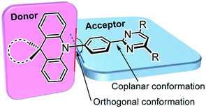 | ||
| Fig. 1 Molecular design and preferred geometry of deep-blue TADF emitters based on pre-twisted acridan–pyrimidine D–A structures. | ||
Results and discussion
Molecular design and synthesis
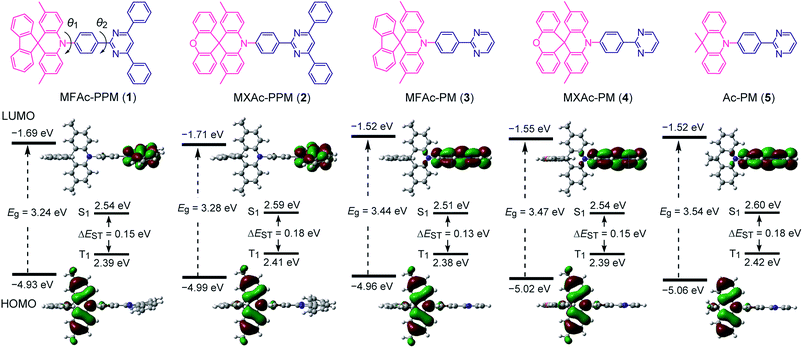
As shown in Fig. 2, we designed a new series of D–A molecules, 1–5 consisting of 2,4,6-triphenylpyrimidine (PPM) or 2-phenylpyrimidine (PM) as an acceptor and spiro[2,7-dimethylacridan-9,9′-fluorene] (MFAc), spiro[2,7-dimethylacridan-9,9′-xanthene] (MXAc), or 9,9-dimethylacridan (Ac) as a donor. The selection of the PPM and PM units which have relatively weak electron-withdrawing characteristics and intrinsic high T1 energies is key to producing wide-bandgap deep-blue TADF materials. Our design strategy is justified by time-dependent density functional theory (TD-DFT) calculations, which provide insights into the geometrical and electronic properties of 1–5 at the molecular level. As can be seen from Fig. 2, all of these molecules adopt highly twisted D–A conformations in their optimized geometries, with dihedral angles between the acridan unit and the adjacent phenylene ring (θ1) of 87–90° owing to the steric repulsion arising from their peri-hydrogen atoms. Meanwhile, the dihedral angles between the pyrimidine ring and the central phenylene ring (θ2) were rather small (<6°). Such nearly orthogonal molecular structures formed by 1–5 can effectively break the π-conjugation between the donor and acceptor moieties and cause localization of the HOMO and LUMO primarily on the acridan and PPM (or PM) units, respectively. Besides, the calculated first excited S1 states for 1–5 were dominated by the HOMO → LUMO intramolecular charge-transfer (ICT) transition. As a result, small ΔEST values in the range of 0.13–0.18 eV were estimated for 1–5 from the calculated S1 and T1 energies (Fig. 2), allowing for efficient RISC and consequently resulting in TADF emission.The configuration of 1 was further verified using X-ray crystallographic analysis (Fig. 3). As per our design, 1 revealed a highly twisted molecular structure with a dihedral angle between the acridan unit and the adjacent phenylene ring of 80°, reasonably consistent with the TD-DFT calculations. It is also noted that the spiro-fused fluorene substituent caused a slight bending of the acridan unit along the C9–N10 axis, on account of the sp3 character of the C9 atom.
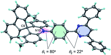 | ||
| Fig. 3 ORTEP diagram of 1 with 50% probability ellipsoids. Atom color code: C, gray; N, blue; H, light-blue. | ||
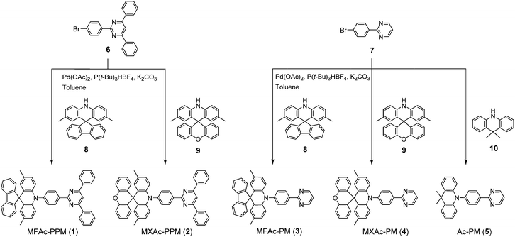
Compounds 1–5 were readily synthesized in high yields of over 90% through the Buchwald–Hartwig amination of bromo-PPM (for 1 and 2) or bromo-PM (for 3–5) with the corresponding spiroacridan/acridan by employing a Pd(OAc)2/P(t-Bu)3HBF4 catalytic system. All final products were purified using temperature-gradient vacuum sublimation to obtain highly pure materials for subsequent measurements and device fabrication. The chemical structures of 1–5 were confirmed using 1H and 13C NMR spectroscopy, mass spectrometry and elemental analysis. The detailed synthetic procedures and characterization data are described in the Experimental section and ESI.† The thermal properties of 1–5 were examined using thermogravimetric analysis (ESI†). Among these new compounds, 1 and 2 possessed the highest thermal stability with a decomposition temperature (Td, corresponding to 5% weight loss) of 422 °C. Such a Td value was much higher than those of 3–5 (Td = 351, 354, and 288 °C, respectively). The D–A molecules bearing the spiro-fused D units (MFAC and MXAc) were found to exhibit better thermal properties than that with the non-spiro Ac unit.
Photophysical and TADF properties
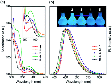
The steady-state UV-vis absorption and photoluminescence (PL) spectra of 1–5 in dilute solution are depicted in Fig. 4 and their relevant photophysical data are summarized in Table 1. All these compounds exhibit similar spectral features which involve two major absorption bands. While the stronger higher-energy absorptions below 330 nm are attributed to the π–π* transitions of the conjugated aromatic units, the much weaker lower-energy absorptions spanning the range of 350–400 nm are assigned to the ICT transitions associated with electron transfer from the acridan to the pyrimidine moieties. Upon photoexcitation at the ICT absorption band, 1–5 in toluene solution exhibited intense deep-blue PL emission with peaks (λPL) ranging from 448 to 460 nm.| λ abs (nm) | λ PL (nm) | λ PL (nm) | CIEb,c (x, y) | Φ PL , (%) | τ p (ns) | τ d (μs) | HOMOf (eV) | LUMOg (eV) | E S (eV) | E T (eV) | ΔESTi (eV) | |
|---|---|---|---|---|---|---|---|---|---|---|---|---|
| a Measured in toluene solution (10−5 M) at room temperature. b Measured in 18 wt%-doped thin films in a PPF solid host matrix at room temperature. c Commission Internationale de l'Éclairage (CIE) color coordinates. d Absolute PL quantum yield evaluated using an integrating sphere under N2. e PL lifetimes of the prompt (τp) and delayed (τd) decay components for the 18 wt%-doped films measured at room temperature. f Determined using photoelectron yield spectroscopy in neat films. g LUMO = HOMO + Eg, in which the optical energy gap (Eg) was derived from the absorption onset of the neat film. h Lowest singlet (ES) and triplet (ET) energies estimated from the onset wavelengths of the PL spectra at 300 and 5 K in the doped films, respectively. i Singlet–triplet energy splitting determined experimentally using ΔEST = ES − ET. | ||||||||||||
| 1 | 309, 386 | 458 | 464 | (0.15, 0.15) | 87 | 12 | 38 | −5.62 | −2.67 | 3.07 | 2.82 | 0.25 |
| 2 | 306, 378 | 451 | 452 | (0.15, 0.12) | 69 | 11 | 40 | −5.65 | −2.68 | 3.10 | 2.85 | 0.25 |
| 3 | 310, 380 | 461 | 466 | (0.15, 0.18) | 91 | 13 | 45 | −5.60 | −2.69 | 3.06 | 2.80 | 0.26 |
| 4 | 310, 379 | 454 | 458 | (0.15, 0.13) | 90 | 11 | 70 | −5.65 | −2.70 | 3.09 | 2.80 | 0.29 |
| 5 | 286, 359 | 448 | 457 | (0.15, 0.13) | 83 | 11 | 78 | −5.68 | −2.70 | 3.10 | 2.80 | 0.30 |
The photophysical and TADF properties of 1–5 were examined using doped thin films in a solid host matrix. The S1 and T1 energies (ES and ET, respectively) of 1–5 were determined from the onset of the fluorescence (300 K) and phosphorescence (5 K) spectra, respectively, and thus their ΔEST values were experimentally evaluated to be between 0.25–0.30 eV (Table 1 and ESI†). Because of the high ES and ET values of 3.0–3.1 eV and 2.8–2.9 eV, respectively, for these wide-bandgap emitters 1–5, we selected 2,8-bis(diphenylphosphoryl)dibenzo[b,d]furan (PPF)39 with a high ET of 3.1 eV as a suitable host material to prevent the reverse energy transfer from the T1 states of the guest emitter to the host material and to confine the excitons in the emitters. As shown in Fig. 5, the PL emission from these doped films thoroughly originated from their guest emitters (1–5), manifesting an efficient host-to-guest energy transfer. Among these derivatives, MFAc-containing 1 and 3 showed slightly red-shifted PL emissions centered at 464 and 466 nm, respectively, compared with their MXAc-containing counterparts (λPL = 452 and 458 nm for 2 and 4, respectively), presumably because of the enhanced electron-donating effects caused by the conjugated spirofluorene substituent on the C9 position of the acridan unit. The absolute PL quantum yields (ΦPL) of the doped films of 1–5 in PPF are as high as 87%, 69%, 91%, 90%, and 83% under N2, respectively, which are much higher than those obtained in dilute solutions (ΦPL = 32–36% in deoxygenated toluene solution). Such a PL enhancement in the solid state originates from the suppression of the non-radiative deactivation processes caused by collisional and intramolecular rotational excited-energy loss. It is noteworthy that most of these derivatives exhibited CIEx,y values below 0.15 in those solid thin films, demonstrating their suitability as efficient deep-blue emitters in TADF-OLEDs.
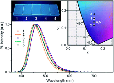 | ||
| Fig. 5 PL spectra of 1–5 in 18 wt%-emitter:PPF doped thin films. The inset shows the CIE chromaticity coordinates and a photograph of the deep-blue PL emission of 1–5 in the doped films. | ||
The TADF characteristics of 1–5 in the doped films were further evidenced by investigating the temperature-dependent transient PL decay. As shown in Fig. 6, each of the transient PL curves displays a clear double-exponential decay profile with prompt and delayed components in oxygen-free conditions. While the prompt component with a lifetime (τp) of 11–13 ns corresponds to conventional fluorescence (S1 → S0), the delayed component with a lifetime (τd) of 38–78 μs can be assigned to TADF involving ISC and RISC processes (S1 → T1 → S1 → S0). In comparison with 4 and 5, the relatively shorter τd for 1–3 can be attributed to their smaller ΔEST values (Table 1). Furthermore, the transient PL profiles of the doped films reveal a typical TADF feature:8 the PL intensity for the delayed component gradually increases when increasing the temperature from 5 to 300 K. These observations unambiguously indicate that 1–5 can indeed utilize T1 excitons for efficient light emission from the S1 state via the T1 → S1 thermal upconversion. From the overall ΦPL value and the proportion of the integrated areas of the two components in each transient PL curve, the fractional quantum efficiencies for the prompt (Φp) and delayed (Φd) components were evaluated for the doped films of 1–5, as given in the insets of Fig. 6. Obviously, these doped films exhibited a high ratio of Φd with respect to the overall ΦPL at ambient temperature (300 K), suggesting that a large portion of the S1 excitons underwent efficient ISC and RISC and then decayed to emit delayed fluorescence upon photoexcitation. Indeed, for 1–5, high RISC efficiencies (ΦRISC) of 44–82% were assumed by the equation:22ΦRISC = Φd/(1 − Φp) (see the ESI for details†).
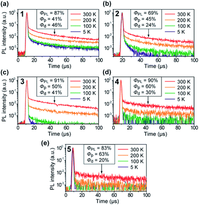 | ||
| Fig. 6 Temperature dependence of the transient PL decay for 1–5 in 18 wt%-emitter:PPF doped thin films in the temperature range of 5–300 K under vacuum. | ||
Electroluminescence performance
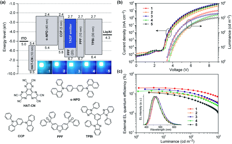
To investigate the EL performance of deep-blue TADF emitters 1–5, multilayer OLEDs were fabricated by employing thin films of 1–5 doped in a PPF host as an emitting layer (EML). We adopted the following device configuration: indium-tin-oxide (ITO, 100 nm)/HAT-CN (10 nm)/α-NPD (40 nm)/CCP (5 nm)/EML (20 nm)/PPF (10 nm)/TPBi (30 nm)/Liq (1 nm)/Al (100 nm), as illustrated in Fig. 7a. In this device architecture, HAT-CN (2,3,6,7,10,11-hexacyano-1,4,5,8,9,12-hexaazatriphenylene) and α-NPD (4,4′-bis-[N-(1-naphthyl)-N-phenylamino]-1,1′-biphenyl) were used as a hole-injection layer and a hole-transporting layer, respectively; whereas, TPBi (1,3,5-tris(N-phenylbenzimidazol-2-yl)benzene) and Liq (8-hydroxyquinoline lithium) served as an electron-transporting layer and an electron-injection material, respectively. Additionally, thin layers of CCP33 (9-phenyl-3,9′-bicarbazole) and PPF39 with a high ET of 3.0 and 3.1 eV were inserted as exciton-blocking layers to suppress the triplet exciton deactivation at the neighboring interfaces and to confine the excitons within the EML.The EL characteristics of the fabricated TADF-OLEDs are depicted in Fig. 7b and c, and the key device parameters are compiled in Table 2. The devices based on 1–5 displayed bright blue EL emission peaking in the range of 458–470 nm, with rather low turn-on voltages (Von) of 3.4–3.6 V. Their EL spectra were consistent with the corresponding PL spectra, suggesting efficient carrier injection, transport, and recombination into the EML within the device. Among the fabricated devices, the device employing 1 achieved the highest EL efficiencies with a maximum ηext of 20.4%, current efficiency (ηc) of 41.7 cd A−1, and power efficiency (ηp) of 37.2 lm W−1 at low current densities without any light out-coupling enhancement. The CIE coordinates of the EL from this device were (0.16, 0.23). To our knowledge, these efficiencies are among the highest level for blue TADF-OLEDs ever reported.10,16,21,22,29,33,34,38 So far, deep-blue TADF-OLEDs with emission maxima (λEL) below 470 nm have rarely achieved a high ηext exceeding 20%. Moreover, the device employing 1 also showed a relatively reduced efficiency roll-off compared to the other devices; the ηext value still remained as high as 15.6% at a practical luminance of 100 cd m−2. The reduced roll-off behavior for 1 can be attributed to the fast RISC originating from its relatively shorter τd and the suppression of triplet–triplet annihilation (TTA) and singlet–triplet annihilation (STA),40,41 as discussed below.
| Emittera | 1 | 2 | 3 | 4 | 5 |
|---|---|---|---|---|---|
| a Device configuration: ITO/HAT-CN (10 nm)/α-NPD (40 nm)/CCP (5 nm)/18 wt%-emitter:PPF (20 nm)/PPF (10 nm)/TPBi (30 nm)/Liq (1 nm)/Al (100 nm). b EL emission maximum. c Turn-on voltage at a brightness of 1 cd m−2. d Maximum external EL quantum efficiency. e External EL quantum efficiency at 100 cd m−2. f Maximum current efficiency. g Maximum power efficiency. h Commission Internationale de l'Éclairage (CIE) chromaticity coordinates recorded at 10 mA cm−2. | |||||
| λ EL (nm) | 470 | 462 | 469 | 460 | 458 |
| V on (V) | 3.4 | 3.6 | 3.4 | 3.6 | 3.6 |
| η ext,max (%) | 20.4 | 12.2 | 17.1 | 14.3 | 11.4 |
| η ext,100 (%) | 15.6 | 8.2 | 10.9 | 8.4 | 5.4 |
| η c (cd A−1) | 41.7 | 22.7 | 34.3 | 25.0 | 18.9 |
| η p (lm W−1) | 37.2 | 18.8 | 31.7 | 20.7 | 16.5 |
| CIEh (x, y) | (0.16, 0.23) | (0.16, 0.20) | (0.16, 0.21) | (0.16, 0.19) | (0.15, 0.15) |
Comparing the performance of the TADF-OLEDs containing 1–5, the maximum ηext values were in the order of 1 (20.4%) > 3 (17.1%) > 4 (14.3%) > 2 (12.2%) > 5 (11.4%). The relatively lower efficiencies of the devices with 2 and 5 compared to those with 1, 3, and 4 can be mainly ascribed to their lower ΦPL and Φd values. Nevertheless, the ηext values of 2 and 5 were more than two times higher than those expected from conventional fluorescent emitters with the same ΦPL values. These pyrimidine-based deep-blue TADF emitters could thus achieve high EL efficiencies by utilizing both the electro-generated T1 and S1 excitons for efficient light emission. However, the EL efficiencies for some of these TADF-OLEDs significantly decreased with increasing current density (or luminance). This severe efficiency roll-off is primarily attributed to the long-lived excited states of the T1 excitons, which undergo exciton deactivation processes such as TTA and STA. The TTA model is used here to analyze the efficiency roll-off for the devices containing 1–5, according to the following equation:40–42
Conclusions
A new family of deep-blue TADF emitters, consisting of pre-twisted acridan–pyrimidine D–A motifs, were designed and synthesized. All of these emitters in doped thin films showed excellent PL properties with quantum yields of 69–91% accompanied by prominent TADF originating from their small ΔEST. By employing these TADF emitters for OLEDs, considerably high maximum external EL quantum efficiencies of up to 20.4% with CIE coordinates of (0.16, 0.23) were achieved. Deep-blue EL with CIE coordinates of (0.15, 0.15) could also be obtained through rational molecular design in this platform. These results validate a versatile design strategy to utilize pyrimidine derivatives as a universal platform for the further development of efficient deep-blue organic emitters.Experimental section
Materials and synthesis
All commercially available reagents and solvents were used as received unless otherwise noted. 2,8-Bis(diphenylphosphoryl)dibenzo[b,d]furan (PPF)39 and 9-phenyl-3,9′-bicarbazole (CCP)33 were prepared according to the literature procedures, and were purified using vacuum sublimation. 2,3,6,7,10,11-Hexacyano-1,4,5,8,9,12-hexaazatriphenylene (HAT-CN) was donated by Nippon Soda Co., Ltd. and was purified using vacuum sublimation before use. Other OLED materials were purchased from E-Ray Optoelectronics Technology Co., Ltd. and were used for the device fabrication without further purification. The synthesis routes for deep-blue TADF molecules 1–5 are outlined in Scheme 1, and detailed synthetic procedures and characterization data for other intermediates (6–9) are given in the ESI.† 9,9-Dimethylacridan43 (10) was prepared according to the literature procedure. All final products were purified using temperature-gradient vacuum sublimation with a P-100 system (ALS Technology), before the measurements and device fabrication.![[thin space (1/6-em)]](https://www.rsc.org/images/entities/char_2009.gif) :
:![[thin space (1/6-em)]](https://www.rsc.org/images/entities/char_2009.gif) 1, v/v) to afford 1 as a white solid (yield = 1.60 g, 93%). 1H NMR (400 MHz, DMSO-d6): δ 9.03 (d, J = 8.4 Hz, 2H), 8.67 (s, 1H), 8.60–8.58 (m, 4H), 7.99 (d, J = 7.6 Hz, 2H), 7.78 (d, J = 8.4 Hz, 2H), 7.68–7.66 (m, 6H), 7.45 (td, J = 7.4 Hz, 1.3 Hz, 2H), 7.41 (d, J = 7.2 Hz, 2H), 7.33 (td, J = 7.2 Hz, 1.2 Hz, 2H), 6.80 (dd, J = 8.6 Hz, 1.8 Hz, 2H), 6.32 (d, J = 8.4 Hz, 2H), 6.04 (d, J = 1.6 Hz, 2H), 1.90 (s, 6H). 13C NMR (100 MHz, CDCl3): δ 165.04, 164.02, 156.52, 143.81, 139.24, 139.22, 138.16, 137.39, 131.38, 131.19, 130.98, 129.48, 129.03, 128.40, 128.00, 127.87, 127.45, 127.34, 125.86, 124.63, 119.83, 114.52, 110.55, 56.92, 20.40. MS (MALDI-TOF): m/z calcd 665.28 [M]+; found 665.18. Anal. calcd (%) for C49H35N3: C 88.39, H 5.30, N 6.31; found: C 88.35, H 5.23, N 6.34.
1, v/v) to afford 1 as a white solid (yield = 1.60 g, 93%). 1H NMR (400 MHz, DMSO-d6): δ 9.03 (d, J = 8.4 Hz, 2H), 8.67 (s, 1H), 8.60–8.58 (m, 4H), 7.99 (d, J = 7.6 Hz, 2H), 7.78 (d, J = 8.4 Hz, 2H), 7.68–7.66 (m, 6H), 7.45 (td, J = 7.4 Hz, 1.3 Hz, 2H), 7.41 (d, J = 7.2 Hz, 2H), 7.33 (td, J = 7.2 Hz, 1.2 Hz, 2H), 6.80 (dd, J = 8.6 Hz, 1.8 Hz, 2H), 6.32 (d, J = 8.4 Hz, 2H), 6.04 (d, J = 1.6 Hz, 2H), 1.90 (s, 6H). 13C NMR (100 MHz, CDCl3): δ 165.04, 164.02, 156.52, 143.81, 139.24, 139.22, 138.16, 137.39, 131.38, 131.19, 130.98, 129.48, 129.03, 128.40, 128.00, 127.87, 127.45, 127.34, 125.86, 124.63, 119.83, 114.52, 110.55, 56.92, 20.40. MS (MALDI-TOF): m/z calcd 665.28 [M]+; found 665.18. Anal. calcd (%) for C49H35N3: C 88.39, H 5.30, N 6.31; found: C 88.35, H 5.23, N 6.34.
![[thin space (1/6-em)]](https://www.rsc.org/images/entities/char_2009.gif) :
:![[thin space (1/6-em)]](https://www.rsc.org/images/entities/char_2009.gif) 1, v/v) to afford 3 as a white solid (yield = 2.01 g, 92%). 1H NMR (400 MHz, DMSO-d6): δ 9.02 (d, J = 4.8 Hz, 2H), 8.77 (dd, J = 6.4 Hz, 2.0 Hz, 2H), 7.98 (d, J = 7.6 Hz, 2H), 7.71 (dd, J = 6.8 Hz, 2.0 Hz, 2H), 7.55 (t, J = 4.8 Hz, 1H), 7.44 (td, J = 7.2 Hz, 1.2 Hz, 2H), 7.39 (d, J = 7.2 Hz, 2H), 7.32 (td, J = 7.2 Hz, 1.2 Hz, 2H), 6.78 (dd, J = 8.8 Hz, 1.9 Hz, 2H), 6.26 (d, J = 8.4 Hz, 2H), 6.03 (d, J = 2.0 Hz, 2H), 1.89 (s, 6H). 13C NMR (100 MHz, CDCl3): δ 164.24, 157.44, 156.51, 144.01, 139.24, 139.14, 137.55, 131.58, 130.86, 129.52, 128.39, 127.98, 127.89, 127.45, 125.84, 124.61, 119.82, 119.39, 114.45, 56.88, 20.39. MS (MALDI-TOF) m/z: calcd 513.22 [M]+; found 514.04. Anal. calcd (%) for C37H27N3: C 86.52, H 5.30, N 8.18; found: C 86.64, H 5.06, N 8.23.
1, v/v) to afford 3 as a white solid (yield = 2.01 g, 92%). 1H NMR (400 MHz, DMSO-d6): δ 9.02 (d, J = 4.8 Hz, 2H), 8.77 (dd, J = 6.4 Hz, 2.0 Hz, 2H), 7.98 (d, J = 7.6 Hz, 2H), 7.71 (dd, J = 6.8 Hz, 2.0 Hz, 2H), 7.55 (t, J = 4.8 Hz, 1H), 7.44 (td, J = 7.2 Hz, 1.2 Hz, 2H), 7.39 (d, J = 7.2 Hz, 2H), 7.32 (td, J = 7.2 Hz, 1.2 Hz, 2H), 6.78 (dd, J = 8.8 Hz, 1.9 Hz, 2H), 6.26 (d, J = 8.4 Hz, 2H), 6.03 (d, J = 2.0 Hz, 2H), 1.89 (s, 6H). 13C NMR (100 MHz, CDCl3): δ 164.24, 157.44, 156.51, 144.01, 139.24, 139.14, 137.55, 131.58, 130.86, 129.52, 128.39, 127.98, 127.89, 127.45, 125.84, 124.61, 119.82, 119.39, 114.45, 56.88, 20.39. MS (MALDI-TOF) m/z: calcd 513.22 [M]+; found 514.04. Anal. calcd (%) for C37H27N3: C 86.52, H 5.30, N 8.18; found: C 86.64, H 5.06, N 8.23.
Photophysical measurements
The UV-vis absorption and photoluminescence (PL) spectra were measured with a V-670 spectrometer (Jasco) and a FP-8600 spectrophotometer (Jasco), respectively, using degassed spectral grade solvents. The absolute PL quantum yields (ΦPL) were determined using an ILF-835 integrating sphere system (Jasco). The transient PL decay measurements were carried out using a C11367 Quantaurus-tau fluorescence lifetime spectrometer (Hamamatsu Photonics; λ = 340 nm, pulse width = 100 ps, and repetition rate = 20 Hz) under N2, and a C9300 streak camera (Hamamatsu Photonics) with an N2 gas laser (λ = 337 nm, pulse width = 500 ps, and repetition rate = 20 Hz) under vacuum (<4 × 10⁻¹ Pa). The HOMO energies of materials in neat films were determined using an AC-2 ultraviolet photoelectron spectrometer (Riken-Keiki). The LUMO energies were estimated by subtracting the optical energy gaps (Eg) from the measured HOMO energies; the Eg values were determined from the onset positions of the PL spectra of the thin films.OLED fabrication and characterization
ITO-coated glass substrates were cleaned with detergent, deionized water, acetone, and isopropanol. The substrates were then subjected to UV–ozone treatment for 30 min before they were loaded into an E-200 vacuum evaporation system (ALS Technology). The organic layers and a cathode aluminum layer were thermally evaporated onto the substrates under vacuum (<6 × 10⁻⁵ Pa) with an evaporation rate of <0.3 nm s−1 through a shadow mask. The layer thickness and deposition rate were monitored in situ during deposition using an oscillating quartz thickness monitor. OLED characteristics were measured using a 2400 source meter (Keithley) and a CS-2000 spectroradiometer (Konica Minolta).Acknowledgements
This work was supported in part by Grant-in-Aid for Scientific Research on Innovative Areas (No. 15H01049) from JSPS, the Cooperative Research Program of “Network Joint Research Center for Materials and Devices”, the Canon Foundation, the Sumitomo Electric Group CSR Foundation, the Futaba Electronics Memorial Foundation, and the KDDI Foundation. I. P. acknowledges the support from the Rotary Yoneyama Scholarships. The authors thank Dr N. Aizawa for fruitful discussion regarding this work.References
- C. W. Tang and S. A. VanSlyke, Appl. Phys. Lett., 1987, 51, 913 CrossRef CAS.
- M. A. Baldo, S. Lamansky, P. E. Burrows, M. E. Thompson and S. R. Forrest, Appl. Phys. Lett., 1999, 75, 4 CrossRef CAS.
- C. Adachi, M. A. Baldo, M. E. Thompson and S. R. Forrest, J. Appl. Phys., 2001, 90, 5048 CrossRef CAS.
- S. Reineke, F. Lindner, G. Schwartz, N. Seidler, K. Walzer, B. Lüssem and K. Leo, Nature, 2009, 459, 234 CrossRef CAS PubMed.
- H. Yersin, Highly Efficient OLEDs with Phosphorescent Materials, Wiley-VCH, Weinheim, Germany, 2008 Search PubMed.
- K. S. Yook and J. Y. Lee, Adv. Mater., 2012, 24, 3169 CrossRef CAS PubMed.
- M. Zhu and C. Yang, Chem. Soc. Rev., 2013, 42, 4963 RSC.
- H. Uoyama, K. Goushi, K. Shizu, H. Nomura and C. Adachi, Nature, 2012, 492, 234 CrossRef CAS PubMed.
- S. Hirata, Y. Sakai, K. Masui, H. Tanaka, S. Y. Lee, H. Nomura, N. Nakamura, M. Yasumatsu, H. Nakanotani, Q. Zhang, K. Shizu, H. Miyazaki and C. Adachi, Nat. Mater., 2014, 14, 330 CrossRef PubMed.
- Q. Zhang, B. Li, S. Huang, H. Nomura, H. Tanaka and C. Adachi, Nat. Photonics, 2014, 8, 326 CrossRef CAS.
- Q. Zhang, D. Tsang, H. Kuwabara, Y. Hatae, B. Li, T. Takahashi, S. Y. Lee, T. Yasuda and C. Adachi, Adv. Mater., 2015, 27, 2096 CrossRef CAS PubMed.
- H. Kaji, H. Suzuki, T. Fukushima, K. Shizu, K. Suzuki, S. Kubo, T. Komino, H. Oiwa, F. Suzuki, A. Wakamiya, Y. Murata and C. Adachi, Nat. Commun., 2015, 6, 8476 CrossRef CAS PubMed.
- R. Komatsu, H. Sasabe, Y. Seino, K. Nakao and J. Kido, J. Mater. Chem. C, 2016, 4, 2274 RSC.
- K. Wu, T. Zhang, L. Zhan, C. Zhong, S. Gong, N. Jiang, Z.-H. Lu and C. Yang, Chem.–Eur. J., 2016, 22, 10860 CrossRef CAS PubMed.
- M. Kim, S. K. Jeon, S.-H. Hwang and J. Y. Lee, Adv. Mater., 2015, 27, 2515 CrossRef CAS PubMed.
- J. W. Sun, J. Y. Baek, K.-H. Kim, C.-K. Moon, J.-H. Lee, S.-K. Kwon, Y.-H. Kim and J.-J. Kim, Chem. Mater., 2015, 27, 6675 CrossRef CAS.
- T.-A. Lin, T. Chatterjee, W.-L. Tsai, W.-K. Lee, M.-J. Wu, M. Jiao, K.-C. Pan, C.-L. Yi, C.-L. Chung, K.-T. Wong and C.-C. Wu, Adv. Mater., 2016, 28, 6976 CrossRef CAS PubMed.
- Q. Zhang, J. Li, K. Shizu, S. Huang, S. Hirata, H. Miyazaki and C. Adachi, J. Am. Chem. Soc., 2012, 134, 14706 CrossRef CAS PubMed.
- S. Wu, M. Aonuma, Q. Zhang, S. Huang, T. Nakagawa, K. Kuwabara and C. Adachi, J. Mater. Chem. C, 2014, 2, 421 RSC.
- M. Liu, Y. Seino, D. Chen, S. Inomata, S.-J. Su, H. Sasabe and J. Kido, Chem. Commun., 2015, 51, 16353 RSC.
- I. Lee and J. Y. Lee, Org. Electron., 2016, 29, 160 CrossRef CAS.
- S. Y. Lee, C. Adachi and T. Yasuda, Adv. Mater., 2016, 28, 4626 CrossRef CAS PubMed.
- S. Y. Lee, T. Yasuda, Y. S. Yang, Q. Zhang and C. Adachi, Angew. Chem., Int. Ed., 2014, 53, 6402 CrossRef CAS PubMed.
- P. Rajamalli, N. Senthilkumar, P. Gandeepan, C.-Z. Ren-Wu, H.-W. Lin and C.-H. Cheng, J. Mater. Chem. C, 2016, 4, 900 RSC.
- P. Rajamalli, N. Senthilkumar, P. Gandeepan, P.-Y. Huang, M.-J. Huang, C.-Z. Ren-Wu, C.-Y. Yang, M.-J. Chiu, L.-K. Chu, H.-W. Lin and C.-H. Cheng, J. Am. Chem. Soc., 2016, 138, 628 CrossRef CAS PubMed.
- Z. Wang, Y. Li, X. Cai, D. Chen, G. Xie, K. Liu, Y.-C. Wu, C.-C. Lo, A. Lien, Y. Cao and S.-J. Su, ACS Appl. Mater. Interfaces, 2016, 8, 8627 CAS.
- I. S. Park, S. Y. Lee, C. Adachi and T. Yasuda, Adv. Funct. Mater., 2016, 26, 1813 CrossRef CAS.
- Y. J. Cho, K. S. Yook and J. Y. Lee, Sci. Rep., 2015, 5, 7859 CrossRef CAS PubMed.
- D. Zhang, M. Cai, Y. Zhang, D. Zhang and L. Duan, Mater. Horiz., 2016, 3, 145 RSC.
- D. Zhang, M. Cai, Z. Bin, Y. Zhang, D. Zhang and L. Duan, Chem. Sci., 2016, 7, 3355 RSC.
- Y. J. Cho, S. K. Jeon, B. D. Chin, E. Yu and J. Y. Lee, Angew. Chem., Int. Ed., 2015, 54, 5201 CrossRef CAS PubMed.
- W. Liu, C.-J. Zhang, K. Wang, Z. Chen, D.-Y. Chen, F. Li, X.-M. Ou, Y.-P. Dong and X.-H. Zhang, ACS Appl. Mater. Interfaces, 2015, 7, 18930 CAS.
- M. Numata, T. Yasuda and C. Adachi, Chem. Commun., 2015, 51, 9443 RSC.
- T. Hatakeyama, K. Shiren, K. Nakajima, S. Nomura, S. Nakatsuka, K. Kinoshita, J. Ni, Y. Ono and T. Ikuta, Adv. Mater., 2016, 28, 2777 CrossRef CAS PubMed.
- I. S. Park, M. Numata, C. Adachi and T. Yasuda, Bull. Chem. Soc. Jpn., 2016, 89, 375 CrossRef CAS.
- Y. Kitamoto, T. Namikawa, D. Ikemizu, Y. Miyata, T. Suzuki, H. Kita, T. Sato and S. Oi, J. Mater. Chem. C, 2015, 3, 9122 RSC.
- K. Suzuki, S. Kubo, K. Shizu, T. Fukushima, A. Wakamiya, Y. Murata, C. Adachi and H. Kaji, Angew. Chem., Int. Ed., 2015, 54, 15231 CrossRef CAS PubMed.
- I. S. Park, J. Lee and T. Yasuda, J. Mater. Chem. C, 2016, 4, 7911 RSC.
- P. A. Vecchi, A. B. Padmaperuma, H. Qiao, L. S. Sapochak and P. E. Burrows, Org. Lett., 2006, 8, 4211 CrossRef CAS PubMed.
- C. Murawski, K. Leo and M. C. Gather, Adv. Mater., 2013, 25, 6801 CrossRef CAS PubMed.
- M. A. Baldo, C. Adachi and S. R. Forrest, Phys. Rev. B: Condens. Matter, 2000, 62, 10967 CrossRef CAS.
- C. Adachi, M. A. Baldo and S. R. Forrest, J. Appl. Phys., 2000, 87, 8049 CrossRef CAS.
- T. Takahashi, K. Shizu, T. Yasuda, K. Togashi and C. Adachi, Sci. Technol. Adv. Mater., 2014, 15, 034202 CrossRef.
Footnote |
| † Electronic supplementary information (ESI) available: General methods, synthesis and characterization data for intermediates, additional computational and photophysical data, TGA data, and OLED device characteristics. CCDC 1500786. For ESI and crystallographic data in CIF or other electronic format see DOI: 10.1039/c6sc03793c |
| This journal is © The Royal Society of Chemistry 2017 |

