 Open Access Article
A sensitivity analysis of a numbered-up photomicroreactor system†
Koen P. L.
Kuijpers
a,
Mark A. H.
van Dijk
a,
Quentin G.
Rumeur
a,
Volker
Hessel
a,
Yuanhai
Su
*b and
Timothy
Noël
 *a
*a
aMicro Flow Chemistry and Process Technology, Department of Chemical Engineering and Chemistry, Eindhoven University of Technology, Den Dolech 2, 5600 MB Eindhoven, The Netherlands. E-mail: t.noel@tue.nl; Tel: +31 40 247 3623
bDepartment of Chemical Engineering, School of Chemistry and Chemical Engineering, Shanghai Jiao Tong University, Shanghai, P.R. China. E-mail: y.su@sjtu.edu.cn
First published on 13th March 2017
Abstract
Limitations with regard to the scalability of photochemical reactions can be efficiently overcome by using numbered-up microreactor technology. Here, the robustness of such a numbered-up capillary photomicroreactor system is tested when subjected to potential disturbances, such as channel blockage and light source failure. Channel blockage leads to relatively large changes in both flow distribution and yield. However, we found that the performance can be accurately predicted thus making it possible to adjust the reaction parameters to obtain certain output targets. Light source failure did not lead to large variations in the mass flow distribution, highlighting the importance of the flow distributor section. Since the reaction is photocatalyzed, the impact on the reaction yield was significant in the reactor where the light failure occurred.
1. Introduction
Process safety, process efficiency and environmentally benign technologies gain increasing amounts of attention in both academia and industry. To improve these important process aspects, microreactors have been suggested as enabling technologies providing enhanced transport phenomena (i.e. mass, heat and photon).1,2 With respect to photochemical transformations, the use of visible light can contribute to develop more energy efficient processes. Such processes allow to use cheap light sources, such as compact fluorescent light bulbs (CFL) or light-emitting diodes (LEDs), and can be even carried out with solar irradiation.3 Moreover, visible light driven photoredox catalysis gained popularity in the pharmaceutical industry as it allows to access previously elusive reaction pathways and it provides great functional group tolerance due to the mild conditions, e.g. room temperature, atmospheric pressure and lower energy irradiation.4–8 Consequently, visible-light photochemistry provides a greener and safer alternative to conventional reaction pathways.Microreactors constitute the ideal reactor platform to carry out light stimulated reactions, as these reactors can overcome the light attenuation effect (Bougueur–Lambert–Beer law).4,9–11 Typically, photon transport occurs only on a sub-mm scale since the energy is rapidly absorbed by the reaction medium. Sub-mm characteristic dimensions in conjunction with excellent mixing can provide a homogeneous irradiated reaction medium. Furthermore, the reaction time and temperature can be easily controlled in a microreactor, allowing to effectively minimize the formation of by-products, which arise from e.g. over-irradiation. Microreactors display also excellent mass transport properties making them perfectly suited for heterogeneous gas–liquid reactions.
Besides all these advantages, the throughput of a single microreactor is typically insufficient for industrial scale production.12 Traditional scale-up approaches comprise an increase of the channel diameter (scale-out).13 Such an approach is, however, not feasible for photochemical transformations due to the attenuation effect. However, we and others have recently demonstrated that a numbering-up approach can be a powerful strategy to increase the overall throughput of the process whilst keeping all operating conditions constant.14–19 Numbering-up is an approach in which several microdevices are placed in parallel. When a single pumping system is used (internal numbering up), the flow must be evenly directed over the parallel reactor channels via a flow distributor. However, equal flow distribution over the different channels can be challenging, especially for gas–liquid flow.20–22
Multiple factors (e.g. fabrication errors, clogging, light failure) can cause flow maldistribution.23 While fabrication errors can be remediated prior to the launch of a production campaign, channel blockage and light source failure deteriorate the performance of the numbered-up system during operation.24–26 In this work, we carry out a thorough sensitivity analysis with regard to these disturbances. More specifically, we investigate its effect on the overall performance (i.e. flow distribution and product yield) of our numbered-up photomicroreactor system.14
2. Experimental
2.1 Dimerization of thiophenol via photocatalytic aerobic oxidation
Disulfide bonds are widely found in applications ranging from rubber vulcanization agents to pharmaceuticals. We have developed a number of photocatalytic approaches which allow for the mild synthesis of these compounds.27,28 For this work, we used the photocatalytic oxidation of thiophenol to diphenyl disulfide as a benchmark reaction for the sensitivity analysis (Scheme 1).27 The reaction utilizes Eosin Y as an inexpensive and metal-free photocatalyst, oxygen gas as the oxidant, N,N,N′,N′-tetramethylethane-1,2-diamine (TMEDA) as the base and ethanol as a cheap and green solvent. In flow, this reaction can be completely converted within two minutes while it would take up to 16 hours to complete in batch. This acceleration in flow can be attributed to the optimal gas–liquid mass transfer and the homogeneous irradiation profile. Consequently, such a kinetically fast reaction system is perfectly suited to evaluate the robustness of the numbered-up microreactor system.14,29 | ||
| Scheme 1 Dimerization of thiophenol to diphenyl disulfide via photocatalytic aerobic oxidation with Eosin Y as photocatalyst. | ||
2.2 Scaled-up multi-capillary photomicroreactor design
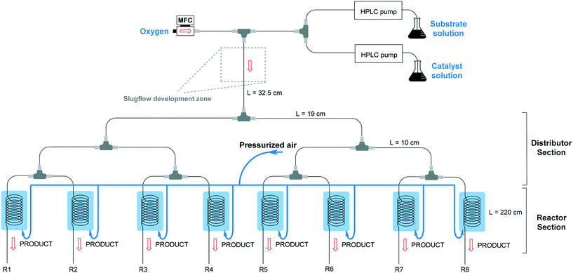
The numbered-up capillary photomicroreactor system comprises two main sections, i.e. a distributor section and a reactor section (Fig. 1). The entire assembly is solely constructed from commercially available parts and the total assembly time is about one hour, even for non-experts.29,30 The bifurcated distribution is enabled by the use of T-micromixers (PEEK, 1/16′′, 1 mm ID, IDEX Health & Science, Part No. P-714). Consequently, the gas–liquid flow can be split into 2n streams. In this manuscript, n equals 3 resulting in a reactor section with eight parallel capillary microreactors. The transparent microcapillaries are made of high purity perfluoroalkoxy alkane (PFA, 0.75 mm ID, IDEX Health & Science, Part No. 1622L).31 White light-emitting diode (LED) strips (Paulmann 703.18, 4.8 W, 420 lm, 1.5 m, 12 V) were coiled around the reactor to furnish the required photons. In order to control the temperature (23 °C ± 3 °C), pressurized air was used to cool the reactors. A schematic representation can be seen in Fig. 1.Two liquid solutions, the substrate solution and the catalyst solution, are pumped into the system via two HPLC pumps (Knauer HPLC pump 1050) and are then combined via a T-micromixer to form a single liquid flow. The substrate solution consists of 0.5 M thiophenol in ethanol and α,α,α-trifluorotoluene as an internal standard, while the catalyst solution consists of 1 mol% Eosin Y and 1 equivalent TMEDA as a base in ethanol. The combined liquid flow is merged with an oxygen gas flow, controlled by a mass flow controller (Bronkhorst), resulting in a gas–liquid segmented flow. The segmented flow is then divided into multiple channels via the distributor section. After steady state was reached, samples were collected at the outlets of the eight reactors and quenched with a saturated ammonium chloride (NH4Cl) solution, diluted with ethyl acetate (EtOAc) and analysed with GC-FID (GC-2010 Plus, Shimadzu). The flow distribution was measured by weighing the output of the different reactors over time.
3. Results and discussion
In our previous paper,14 we already showed that excellent flow distribution could be reached with this setup. Low standard deviation values under reaction conditions (SDw < 10%) and even lower standard deviations in the absence of any reaction (SDw < 5%) were obtained. The standard deviation (SDw) is calculated according to eqn (1) and (2), where wi is the mass flow rate in a particular reactor channel i, wm is the average mass flow rate and n is the number of reactor channels in the numbered-up system. | (1) |
 | (2) |
3.1 Effect of channel blockage on distribution and yield
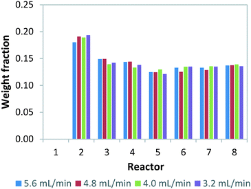
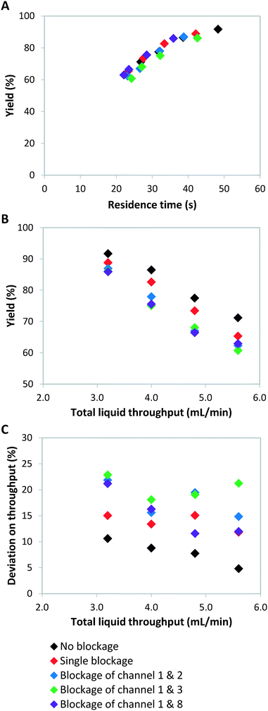
Failure of continuous-flow processing can occur because of channel blockage due to solid precipitation.32,33 Especially for microreactors, clogging remains one of the major hurdles for its widespread implementation.34 In order to simulate microreactor clogging, we closed off one or multiple channels with plugs. Fig. 2 shows the weight distribution when the first photomicroreactor is blocked. Compared to the situation without channel blockage, all the non-blocked reactor channels experience an increase in throughput. The throughput especially increases in the channel which is paired to the blocked one. This is due to the decreased resistance in this particular section of the bifurcation zone. Interestingly, the other six channels seem to have very similar throughputs within the tested flow range. The standard deviation on the throughput is approximately 15% and therefore slightly higher than the regularly operated set-up where no blockage occurs (SDw ≤ 10%). Our experimental results show the same trend as those reported by Su et al.35,36Double channel blockage scenarios are evaluated by respectively blocking reactor 1 and 2, reactor 1 and 3, reactor 1 and 8. For these situations, a higher standard deviation on throughput (SDw up to 25%) is observed, as can be seen in Fig. 3C. In fact, under such scenarios (SDw > 20%), the gas-to-liquid ratio, the residence time and the mass transfer between the two phases varies largely and thus affects the overall reaction performance in the numbered-up microreactor system.
Next, we investigated the effect of channel blockage on the yield of the photocatalytic transformation. The average yield of the reaction and its standard deviation are calculated according to eqn (3) and (4), respectively.
 | (3) |
 | (4) |
As we have described above, the overall flow rate in the non-blocked channels increases according to the total amount of blockages. This flow rate increase implies that shorter average residence times, and thus lower yields, are obtained (Fig. 3). It is clear from Fig. 3B that when channel blockage occurs the average yield drops compared to the non-clogged situation. For the double blockage scenarios, changes in yield of up to 10% were observed (Fig. 3B).
Theoretically, a decrease in residence time (τ) scalable with the number of blocked channels would be expected, as shown in eqn (5). For instance, when one out of eight channels suffers from blockage, an overall residence time of 7/8 times the original residence time is observed. If the kinetic constant (κ) of the reaction is known and the residence time is indeed scalable in presence of blockage, the expected yield can be calculated. For a reaction with first order kinetics,29 this yield can be calculated according to eqn (7).
 | (5) |
 | (6) |
| Y = 1 − e−κτ | (7) |
 | (8) |
 | (9) |
The kinetic constant can be determined viaeqn (6), which represents the integrated standard equation for first order kinetics. This parameter is determined to be κ = 0.0593 s−1 in the numbered-up microreactor in absence of any channel blockage (see ESI†). By applying this kinetic parameter and considering the effect of channel blockage on the residence time (eqn (5)) a comparison between two cases, namely with and without blockage, can be made. This is depicted in eqn (8), where the subscripts nb and b represent the cases of no blockage and blockage, respectively. Obviously, in order to make this comparison the reaction should also obey first order kinetics under blockage. This is checked and can be seen in Fig. 3A, where all data points follow the same first order trend. The theoretical fraction from eqn (8) can then be compared to the experimental results according to eqn (9), where if necessary a correction factor (fc) can be applied. In the ideal case, this correction factor should be 1. Next, the confidence intervals of fc are calculated for the four blockage scenarios we tested. The results are shown in Table 1 (more information on the confidence intervals can be found in the ESI†). From these results, it can be understood that the effect of channel blockage on the yield can be very accurately estimated as the standard error in these intervals is rather small. This information should allow the chemical engineer to automatically adjust the flow rates to ensure a given output target. In the meanwhile, the clogged photomicroreactor can be cleaned or replaced. Consequently, the continuous production of the target compound is not endangered at any moment during the clogging event.
| Case | f c ± σ |
|---|---|
| Single blockage | 1 ± 0.009 |
| Double blockage – channel 1 & 2 | 1 ± 0.016 |
| Double blockage – channel 1 & 3 | 1 ± 0.019 |
| Double blockage – channel 1 & 8 | 1 ± 0.023 |
3.2 Effect of light intensity on flow distribution and yield
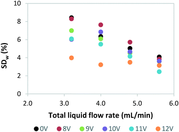
Next, we investigated the effect of light source failure on the performance of our numbered-up photomicroreactor assembly. Failure of a light source is a typical issue for a photomicroreactor as a light source can underperform due to aging or can even suffer from total failure. The light source failure can be simulated by decreasing the power input of the LEDs. That is, the power of the light source in one of the reactors is varied over 12 V (standard voltage of the LED strip), 11 V, 10 V, 9 V, 8 V and 0 V. The influence of the variable power on the flow distribution is depicted in Fig. 4. These results demonstrate that the standard deviation is acceptable in all cases (SDw < 10%). This confirms once more that in such numbered-up systems the distributor section plays the dominant role in the flow partitioning. The ratio of the pressure drop in the distributor section to the pressure drop in the reactor section (see Fig. 1) is the key parameter to obtain proper distribution in gas–liquid flows.20,29 In order to limit flow maldistribution, this ratio should be between 4 and 25. Our study shows that this principle even holds under light failure disturbances.Next, we investigated the influence of light failure on the reaction yield in each photomicroreactor (Fig. 5). It can be seen that the reaction yield significantly lowers when the power input of reactor 1 is lowered. This was expected since lower light input results in less photons which are needed to induce the photochemical transformation. Furthermore, the yields of the other seven reactors seem to remain constant. This data shows the robustness of this scaled-up system and its application potential for continuous production.
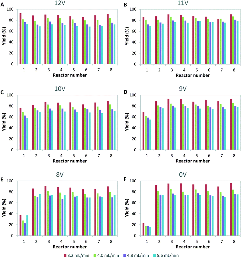 | ||
| Fig. 5 Yield per channel for variable power input of light for reactor 1 of A) 12 V, B) 11 V, C) 10 V, D) 9 V, E) 8 V and F) 0 V. | ||
Conclusions
The flexible scaled-up system used in this research allowed us to measure eight channels individually and therefore an extensive sensitivity analysis based on throughput and yield could be performed. In this study, possible disturbances on a numbered-up photomicroreactor system, like reactor clogging and light source failure, are simulated.Channel blockage has a significant impact on the flow distribution. The standard deviation on the mass flow rate increased from 10% for no blockage, to 15% for single blockage, up to 25% for the double blockage scenario. Obviously, when one channel is blocked, the flow will be distributed over the remaining reactors. We found that the biggest effect was seen on the paired channel. The overall decrease in residence time, together with the kinetics of the reaction, can be used to estimate the overall yield via a standard yield calculation method. This prediction method was validated and shows high accuracy.
The experiments with variable light intensity show that indeed the reaction is highly sensitive to light irradiation. However, the flow distribution is not affected enormously with standard deviations below 10%. This demonstrates that the flow distributor section is crucial in the design of numbered-up microreactor systems.
We believe that this simple yet effective numbering up system can find its way into academia and industry to enable scale up of flow chemistry. Particularly appealing features of our design are the modularity of the setup, the overall cost of the device, the excellent flow distribution and its stability to flow disturbances.
Acknowledgements
Funding for this research was provided by the Dutch Science Foundation (NWO) via a VIDI grant for T. N. (SensPhotoFlow, No. 14150). Y. S. would like to acknowledge financial support from the National Natural Science Foundation of China (No. 21676164). Also, we would like to thank the Loire Atlantique region, France, for their contribution of an Envoléo scholarship appointed to Q. Rumeur. Our gratitude also goes to Rong Fan, who performed preliminary results on the blockage experiments.Notes and references
- T. Noël, Y. Su and V. Hessel, Top. Organomet. Chem., 2016, 57, 1–42 CrossRef.
- R. L. Hartman, J. P. McMullen and K. F. Jensen, Angew. Chem., Int. Ed., 2011, 50, 7502–7519 CrossRef CAS PubMed.
- D. Cambié, F. Zhao, V. Hessel, M. G. Debije and T. Noël, Angew. Chem., Int. Ed., 2017, 56, 1050–1054 CrossRef PubMed.
- Y. Su, N. J. W. Straathof, V. Hessel and T. Noël, Chem. – Eur. J., 2014, 20, 10562–10589 CrossRef CAS PubMed.
- D. Ravelli, S. Protti and M. Fagnoni, Chem. Rev., 2016, 116, 9850–9913 CrossRef CAS PubMed.
- N. A. Romero and D. A. Nicewicz, Chem. Rev., 2016, 116, 10075–10166 CrossRef CAS PubMed.
- J. P. Goddard, C. Ollivier and L. Fensterbank, Acc. Chem. Res., 2016, 49, 1924–1936 CrossRef CAS PubMed.
- D. Staveness, I. Bosque and C. R. Stephenson, Acc. Chem. Res., 2016, 49, 2295–2306 CrossRef CAS PubMed.
- D. Cambié, C. Bottecchia, N. J. W. Straathof, V. Hessel and T. Noël, Chem. Rev., 2016, 116, 10276–10341 CrossRef PubMed.
- M. Oelgemoeller, Chem. Eng. Technol., 2012, 35, 1144–1152 CrossRef.
- J. P. Knowles, L. D. Elliott and K. I. Booker-Milburn, Beilstein J. Org. Chem., 2012, 8, 2025–2052 CrossRef CAS PubMed.
- N. Kockmann, M. Gottsponer and D. M. Roberge, Chem. Eng. J., 2011, 167, 718–726 CrossRef CAS.
- P. Plouffe, M. Bittel, J. Sieber, D. M. Roberge and A. Macchi, Chem. Eng. Sci., 2016, 143, 216–225 CrossRef CAS.
- Y. Su, K. Kuijpers, V. Hessel and T. Noël, React. Chem. Eng., 2016, 1, 73–81 CAS.
- M. Al-Rawashdeh, F. Yu, T. A. Nijhuis, E. V. Rebrov, V. Hessel and J. C. Schouten, Chem. Eng. J., 2012, 207–208, 645–655 CrossRef CAS.
- T. Iwasaki, N. Kawano and J. Yoshida, Org. Process Res. Dev., 2006, 10, 1126–1131 CrossRef CAS.
- W. P. Bula, W. Verboom, D. N. Reinhoudt and H. J. Gardeniers, Lab Chip, 2007, 7, 1717–1722 RSC.
- A. Nagaki, K. Hirose, O. Tonomura, S. Taniguchi, T. Taga, S. Hasebe, N. Ishizuka and J. Yoshida, Org. Process Res. Dev., 2016, 20, 687–691 CrossRef CAS.
- S. Parisien-Collette, A. C. Hernandez-Perez and S. K. Collins, Org. Lett., 2016, 18, 4994–4997 CrossRef CAS PubMed.
- M. Al-Rawashdeh, L. J. M. Fluitsma, T. A. Nijhuis, E. V. Rebrov, V. Hessel and J. C. Schouten, Chem. Eng. J., 2012, 181–182, 549–556 CrossRef CAS.
- J. Chen, S. Wang and S. Cheng, Chem. Eng. Sci., 2012, 84, 706–717 CrossRef CAS.
- J. Chen, S. Wang, X. Zhang, H. Ke and X. Li, Int. J. Heat Mass Transfer, 2015, 81, 939–948 CrossRef CAS.
- C. Amador, A. Gavriilidis and P. Angeli, Chem. Eng. J., 2004, 101, 379–390 CrossRef CAS.
- M. Saber, J. M. Commenge and L. Falk, Chem. Eng. Sci., 2010, 65, 372–379 CrossRef CAS.
- Y. S. Wada, M. A. Schmidt and K. F. Jensen, Ind. Eng. Chem. Res., 2006, 45, 8036–8042 CrossRef CAS.
- P. Pfeifer, A. Wenka, K. Schubert, M. A. Liauw and G. Emig, AIChE J., 2004, 50, 418–425 CrossRef CAS.
- A. Talla, B. Driessen, N. J. W. Straathof, L. G. Milroy, L. Brunsveld, V. Hessel and T. Noël, Adv. Synth. Catal., 2015, 357, 2180–2186 CrossRef CAS.
- C. Bottecchia, N. Erdmann, P. M. A. Tijssen, L. G. Milroy, L. Brunsveld, V. Hessel and T. Noël, ChemSusChem, 2016, 9, 1781–1785 CrossRef CAS PubMed.
- Y. Su, V. Hessel and T. Noël, AIChE J., 2015, 61, 2215–2227 CrossRef CAS.
- Y. Su, A. Talla, V. Hessel and T. Noël, Chem. Eng. Technol., 2015, 38, 1733–1742 CrossRef CAS.
- N. J. W. Straathof, Y. Su, V. Hessel and T. Noël, Nat. Protoc., 2016, 11, 10–21 CrossRef CAS PubMed.
- T. Noël, J. R. Naber, R. L. Hartman, J. P. McMullen, K. F. Jensen and S. L. Buchwald, Chem. Sci., 2011, 2, 287–290 RSC.
- S. Kuhn, T. Noël, L. Gu, P. L. Heider and K. F. Jensen, Lab Chip, 2011, 11, 2488–2492 RSC.
- R. L. Hartman, Org. Process Res. Dev., 2012, 16, 870–887 CrossRef CAS.
- Y. Su, G. Chen and E. Y. Kenig, Lab Chip, 2015, 15, 179–187 RSC.
- Y. Su, A. Lautenschleger, G. Chen and E. Y. Kenig, Ind. Eng. Chem. Res., 2014, 53, 390–401 CrossRef CAS.
Footnote |
| † Electronic supplementary information (ESI) available. See DOI: 10.1039/c7re00024c |
| This journal is © The Royal Society of Chemistry 2017 |

