Investigation of dynamic surface tension in gas–liquid absorption using a microflow interfacial tensiometer
Received
15th October 2016
, Accepted 13th February 2017
First published on 13th February 2017
Abstract
Surface tension is an important parameter that dominates gas–liquid dual-phase flow. In this study, the dynamic surface tension caused by changing substance concentrations at the gas–liquid interface was determined using a microflow interfacial tensiometer. The instantaneous surface tensions at the bubble rupturing moment in a CO2 chemical absorption process were determined from the bubble diameter. The mass transfer across the interface and the chemical reaction within the liquid caused up to a 7.2 mN m−1 reduction in the surface tension, as compared with that in a process without absorption, and the decrease in the surface tension can be expressed into a Langmuir–Szyszkowski equation of the CO2 interfacial concentration. This study clarifies the effect of chemical absorption on multiphase fluid dynamics parameters, which is less discussed in chemistry and chemical engineering studies.
Introduction
Gas–liquid absorption is important for chemical processes, for instance, when introducing a gas compound into a reaction1 or purifying a gas product by dissolving an unrequired gas into a liquid phase.2 To successfully implement such absorption, the fluid dynamics of the gas–liquid dual-phase flow need to be well understood. Since most parameters for gas–liquid contactors—including bubble size and distribution, flow patterns, gas hold-up, and energy dissipation—are related to surface tension, laws for the surface tension variation are essential for understanding gas–liquid absorption processes.3,4
Static surface tension (surface tension in the thermodynamic equilibrium state) is commonly used in gas–liquid fluid dynamic studies,5,6 but is only appropriate for modeling gas–liquid systems without mass transfer and chemical reactions. As with the change in the interface composition, the interfacial tension of the two phases also varies in real chemical processes. Recent publications indicate that varied interfacial tension occurring in multi-phase reactions and solvent extraction processes caused complicated flow phenomena. For example, in the experiment of Ward et al.,7 the reaction of NaOH and oleic acid formed amphiphilic molecules at the interface between mineral oil and water, which induced a tip-streaming flow in a microchannel reactor. Wang et al.8 found that mass transfer of phosphate changed the composition of the water–butanol interface, which decelerated the circular flow in growing droplets, displaying a Marangoni effect. Although these phenomena were observed in liquid–liquid systems, the effects of dynamic interfacial (surface) tension should also exist in gas–liquid systems, such as in gas–liquid absorption processes. However, to the best of our knowledge, the phenomenon of dynamic surface tension has not been well demonstrated in previous gas–liquid dual-phase flow studies, and the laws describing dynamic surface tension in gas–liquid processes are still unclear.
The issue of dynamic interfacial tension has been well investigated in studying emulsification.9,10 Some experiments based on a commercial interfacial tensiometer, such as that using pendent droplets,11 have shown reduced interfacial tension with increasing surfactant adsorption time.12 However, measurement of the dynamic interfacial tension in a process with mass transfer or reaction is a challenge for commercial interfacial tensiometers because of rapid alteration of the interfacial composition. Development of a technique for these measurements is difficult, especially for the gas–liquid system undergoing rapid absorption. Fortunately, the recently developed microflow or microfluidic interfacial tensiometer13,14 provides an appropriate method for investigating rapidly varying surface tension. As the interfacial force (capillary force) is a dominant force in microscale spaces that governs the fluid particle generation and flow,15 it is easy to determine the interfacial tension based on flow parameters. Using the shape of fluid particles in confined microchannels,16,17 or the size of bubbles and droplets generated from microchannel junctions,18,19 even small changes in the interfacial tension can be detected. This level of sensitivity is important for quantifying the dynamic interfacial tension in a chemical process containing non-amphiphilic mass transfer substances. In addition, the time resolution of the microflow interfacial tensiometer is as low as several milliseconds,20 due to the high droplet flow frequency.21 Previous research studies have successfully shown the determination of dynamic interfacial tension during microflow emulsification22 and liquid–liquid extraction.23
Since the surface tension is an important parameter in gas–liquid absorption processes, a microflow interfacial tensiometer was applied to investigate the laws of dynamic surface tension during a CO2 absorption process. We first explored the values of dynamic surface tension in the absorption of CO2 from a CO2–N2 mixture to monoethanolamine–ethylene glycol (MEA–EG) solutions, as new absorbents for CO2 capture.24 The mechanism of the appearance of varied surface tension was then illustrated by analyzing the rates of mass transfer and chemical reaction. The relationship between the dynamic surface tension and the CO2 interfacial concentration was finally confirmed, which is useful for the precise control and implementation of this CO2 absorption process.
Experimental
The dynamic surface tension experiment was implemented in a platform with a microchannel chip. Fig. 1 shows a schematic diagram of the co-flowing bubble-generating structure consisting of an embedded glass capillary and a winding microchannel. The tip of the capillary was used for infusing bubbles with a narrow size distribution (the relative size deviation was less than 3%). This microchannel was fabricated in a poly(methyl methacrylate) (PMMA) plate by precise milling using computer numerical control (CNC), and the chip was sealed using another PMMA plate on a high pressure thermal sealing machine (A274, Techson). The channel was 600 μm in both height and width, with a 90 mm length downstream of the capillary tip. The glass capillary was pulled using a flaming micropipette puller (Sutter Instrument) with a cuspate tip having a diameter of 45 μm. This tinny tip prevented large-area contact between the gas and liquid before a bubble was released. The square cross-section of the channel also allowed flows of spherical bubbles, which is advantageous for measuring the bubble diameter. The meandering channel located downstream of the bubble generation point provided sufficient time for complete absorption.
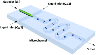 |
| | Fig. 1 Schematic of the microflow interfacial tensiometer. | |
A microscope (BXFM, Olympus) equipped with a high-speed CMOS camera (DK-2740, Dantec Dynamics) was used to record the bubble generation process at a frame frequency of 2000 fps. Both the gas and liquid phases were delivered by syringe pumps (LSP01-1A, Longer). The gas flow rate, QG, was varied from 50 to 125 μL min−1, while the liquid flow rate, QL, was varied from 200 to 750 μL min−1. The bubbles stopped decreasing in size after travelling 25 mm from the tip of the capillary in all experiments. Since the bubble did not enlarge any further in the following microchannel, mass transfer was complete and the pressure drop in the experimental channel was insignificant (the pressure drop calculated using the two-phase model of Yue et al.25 was less than 4 kPa). Finally, the bubble volume at the channel outlet was recorded, and the partial volume of the inert component in the gas mixtures (N2) was taken as equal to this volume.
The experimental system consisted of CO2–N2 mixtures and two MEA–EG solutions with MEA mass percentages of 5% and 15%. The source gases (99.99% purity) were purchased from the Huayuan Company, and analytically pure MEA and EG (99.0%+) were provided by the Beijing Chemical Plant. CO2–N2 mixtures with CO2 volume fractions of 17%, 37%, and 56% were prepared in a gas-tight syringe before the experiments. The viscosities of all liquids were measured using an Ubbelohde viscometer. The viscosities of the gas mixtures and the diffusion coefficients of CO2 in the liquids were evaluated by mixing methods, as described in previous reports.26,27 The static surface tensions of both MEA solutions in N2 were measured using a pendent drop interfacial tensiometer (OCAH200, DataPhysics Instruments). The physical parameters used in this study are summarized in Table 1. The experimental temperature was 28 °C.
Table 1 Physical properties of the experimental systems at 28 °C
| Substances |
Density ρ (g mL−1) |
Surface tension γ (mN m−1) |
Viscosity μ (mPa s) |
CO2 diffusion coefficient DCO2 (m2 s−1) |
| 17% CO2–N2 mixture |
1.27 × 10⁻³ |
— |
1.71 × 10⁻² |
— |
| 37% CO2–N2 mixture |
1.39 × 10⁻³ |
— |
1.58 × 10⁻² |
— |
| 56% CO2–N2 mixture |
1.50 × 10⁻³ |
— |
1.49 × 10⁻² |
— |
| 5% MEA solution |
1.105 |
50.5 (N2) |
15.6 |
0.19 × 10⁻⁹ |
| 15% MEA solution |
1.096 |
50.3 (N2) |
17.4 |
0.17 × 10⁻⁹ |
Results and discussion
Scaling law for bubble diameter without mass transfer
The dynamic surface tension in the microchannel interfacial tensiometer was determined by measuring the diameter of the bubble ruptured from the capillary tip. At the beginning of all the experiments, the relationship between the bubble diameter and the known surface tension was therefore established. Using N2 as the gas phase and both MEA–EG solutions as the liquid continuous phases, the scaling law for the bubble diameter was investigated in a control experiment. By controlling the flow rates of the gas and liquid phases, N2 bubbles were generated in dripping flow, which means that there was not any thread behind those bubbles before they ruptured. Therefore, bubble detachment followed the shear-rupturing mechanism,28,29 and the viscous shear force acting on the bubble was in equilibrium with the interfacial force at the bubble rupturing moment.30 According to this mechanism, the bubble size is primarily controlled by the capillary number,29,31 defined as Ca = μCuC/γ (where μC and uC represent the viscosity and velocity of the continuous phase, respectively, with uC = QL/s; s is the cross-sectional area of the microchannel and γ is the surface tension), as shown in Fig. 2a. A power equation is used to describe the dimensionless bubble diameter db/dh, where db is the bubble diameter and dh is the hydrodynamic diameter of the microchannel, as shown in eqn (1). The coefficients in this equation were determined by fitting the experimental results, with Ca from 0.003 to 0.012.| | 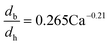 | (1) |
 |
| | Fig. 2 Control experiment for the bubble size scaling law and comparison of the fitting line with the experimental bubble diameters. (a) Dimensionless bubble diameters at different Ca, and (b) linear relationship between db/dh and Ca−0.21. The error bars in the center of the dots show the small deviations in the bubble diameters. | |
The fitting line was in good agreement with the experimental results, as shown in Fig. 2b. Eqn (1) also shows that the bubble size is determined only by Ca, which is related to the physical properties and flow conditions of the continuous phase. These results differ somewhat from our previous results for a similar gas–liquid dripping flow, where the flow rate ratio also had an effect.30 This is because the bubble detachment had a relaxation time in the previous experiment, when the microchip had a larger capillary tip. However, the gas breakup occurred quickly in the current study due to the modified capillary tip diameter. Since obvious density and viscosity differences exist between the gas and liquid phases, and the main forces that dominate bubble generation are all from the continuous phase, the gas composition has been proved to have little effect on the bubble diameter.30 In addition, eqn (1) shows that the bubble diameter is independent of the gas flow rate. Therefore, the advantage of eqn (1) is that it is not dependent on the gas–liquid absorption process. Regardless of the real gas flow rate and concentration at the rupturing moment, the force balance is the only factor determining the bubble size. Using the measured diameter and the known flow conditions of the continuous phase, the dynamic surface tension could then be back-calculated.
Bubble diameter accompanied by mass transfer
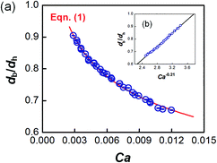
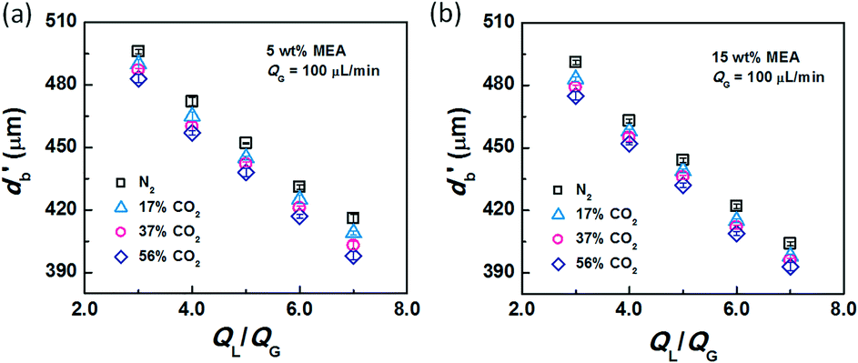
After conducting the control experiment, experiments were carried out using CO2–N2 mixtures as the dispersed phase. The bubble diameters after leaving the capillary tip were measured and recorded. Representative images of bubble formation and flow are shown in Fig. 3. In the bubble-forming stage (Fig. 3a), a bubble expands in the radial and axial directions until it pinches off from the capillary. This process is extremely fast, lasting 2.5–5 ms, which is not long enough to complete CO2 absorption. The average diameter of bubbles immediately after detachment (db′) was used to calculate the surface tension. The last image in Fig. 3a shows that the bubbles are already spherical at this moment. Fig. 3b shows the downstream bubble-flowing stage, in which the bubble shrinks gradually. During this stage, the reduction in bubble size is a result of absorption of CO2 through reaction with MEA. Some values of db′ are shown in Fig. 4. Clearly, the db′ values are somewhat smaller than those in the control experiment with N2 as the gas phase, and this trend becomes more apparent for gas mixtures with higher volume fractions of CO2. Since the resolution of the CMOS camera was 2 μm per pix, the small size reduction was clearly captured. The molar concentrations of MEA were 0.9 mol L−1 (5 wt%) and 2.7 mol L−1 (15 wt%), a large excess for reaction with CO2 (approximately 0.025 mol L−1 in the 56% CO2–N2 mixture). Since the relative amount of CO2 was small, changes in the viscosity of the continuous phase during the absorption processes could be neglected. Therefore, the fact that the bubble sizes were different under identical viscous shear stresses (∼μCuC) implies that the surface tension varies during CO2 absorption.
 |
| | Fig. 3 Representative images of the (a) bubble-forming and (b) bubble-flowing stages in the microchannel. The gas phase was a 56% CO2–N2 mixture at QG = 75 μL min−1 and the liquid phase was a 15 wt% MEA–EG solution at QL = 300 μL min−1. | |
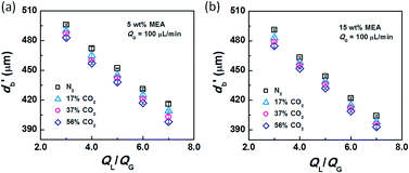 |
| | Fig. 4 Bubble diameters after the rupturing moments. The liquid phases were (a) 5 wt% and (b) 15 wt% MEA–EG solutions, while the gas phase was CO2–N2 with QG = 100 μL min−1. | |
Analysis of dynamic surface tension
In the bubble-forming stage, the varied surface tension was a result of the inconsistent CO2 concentrations at the gas–liquid interface. To quantitatively show the effect of CO2 absorption on the surface tension variation, the dynamic surface tensions were confirmed using eqn (1). Fig. 5 shows the surface tensions at the bubble break-up moments (γ′) calculated from the bubble diameters, db′. In this calculation, the viscous shear stress in the Ca number was calculated from the continuous phase viscosity, μC, and the velocity, uC. Since the apparent velocity, QL/s, does not reflect the Marangoni effect (which accounts for changes in the viscous boundary layer) caused by the interfacial tension gradient on the bubble surface, there are some errors associated with eqn (1). However, the reduction in surface tension was less than 7.2 mN m−1 in this study, which was only 14% of the total surface tension (50.5 mN m−1). We therefore assume that the surface tension gradient was not strong enough to change the viscous boundary layer substantially during bubble growth, especially at the time point when the shear stress and the surface tension reached equilibrium. Fig. 5 shows the space-averaged values for the bubble surface tensions. The error bars in Fig. 5 show the deviations of the dynamic surface tensions, which were all less than 2 mN m−1. These deviations are calculated from the bubble diameter deviations with the first-order Taylor expansion of eqn (1).20
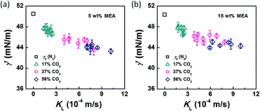 |
| | Fig. 5 Dynamic surface tensions and mass transfer coefficients of CO2 in the bubble-forming stage. The liquid phases were (a) 5 wt% and (b) 15 wt% MEA–EG solutions, and the gases were N2 and CO2–N2 mixtures. | |
Since surface tension changes are caused by the absorption of CO2 by the liquid from the gas mixture, the CO2 mass transfer performance during bubble generation could be determined. As the pressure drop in the microchannel was not obvious and the Laplace pressure from the interface was much lower than the atmospheric pressure for the sub-millimeter-scale bubbles, the pressure in the microchannel, po, was determined to be 1.01 × 10⁵ Pa in the experiment. From this pressure, the average overall mass transfer coefficient, KL, in the bubble-forming stage (defined as the CO2 mass transfer rate per unit mass transfer area per unit concentration difference) was calculated using eqn (2) based on our previous study:32
| | 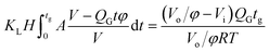 | (2) |
where
H is the Henry constant (
H = 3.61 × 10
−4 mol m
−3 Pa
−1),
33tg is the bubble generation time,
A is the bubble surface area,
V is the bubble volume,
t is time,
QG is the gas feed flow rate,
φ is the original volume fraction of N
2 in the feeding gas mixture,
Vo is the bubble volume at the channel outlet, which is equivalent to the partial volume of N
2 for the completed mass transfer,
Vi is the bubble volume at the rupturing moment, and
RT is from the ideal gas equation of state. Numerical integration was carried out to calculate
KL for each recorded bubble generation process.
32 The dynamic surface tension
versus the CO
2 mass transfer coefficient is therefore shown in
Fig. 5. Clearly, the surface tension decreases more rapidly as the mass transfer rate increases. These results indicate that the surface tension tends to be further from equilibrium when CO
2 mass transfer is significant, thereby leading to a 5–14% reduction in the surface tension value, as compared with the static surface tension without mass transfer (
γ0).
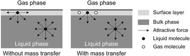
The origin of this dynamic surface tension is further depicted in Fig. 6. Each molecule is surrounded by identical neighbors in the liquid bulk phase, and the sum of the attractive forces is zero. In contrast, molecules in the liquid layer next to the gas–liquid contact line have fewer and different neighbors on the gas side, and thus the forces are not balanced. As the attraction for liquid molecules is greater than that for gas molecules, this results in an asymmetric force that is responsible for the surface tension. Therefore, surface tension is a parameter representing the intermolecular forces in the surface layer, and the composition of this surface layer is closely related to the value of the surface tension. In the presence of absorption, CO2 molecules enter the interfacial region, which changes the composition of the surface layer. This composition change leads to differences in attraction between molecules, weakening the asymmetric molecular force field between the gas and liquid phases. As a result, the surface tension decreases when the CO2 mass transfer rate increases, because there are more CO2 molecules in the surface layer. Comparing Fig. 5a and b, the surface tensions are somewhat larger in the experiment with 15 wt% MEA, which has a higher reaction rate of CO2 and MEA. This phenomenon indicates that the rapid reaction between MEA and CO2, wherein CO2 is fixed by EG,24 further restores the molecular force field in the interface. Therefore, the dynamic surface tension is a result of both the CO2 mass transfer and the chemical reaction in the liquid phase. However, due to the small amount of CO2 transported from the gas to the liquid phase, this reduction in surface tension is somewhat limited compared with that in a liquid–liquid system, in which a reduction of 40% or more in the interfacial tension has been observed.23 In contrast to the emulsification process with a chemically generated surfactant,7 the reaction between CO2 and MEA tends to increase rather than decrease the surface tension.
 |
| | Fig. 6 Schematic explanation of the appearance of dynamic surface tension during absorption processes. | |
Model of dynamic surface tension
According to the above discussion, it could be concluded that the dynamic surface tension is caused by the composition of CO2 in the surface layer. Thus, the relationship between the dynamic surface tension and the CO2 interfacial concentration was finally explored. First, the relationship between the concentration of CO2 and the CO2 mass transfer rate was determined using eqn (3). Since the reaction between CO2 and MEA was fast, the CO2 molecules were mainly present within the liquid layer close to the interface. Accordingly, the CO2 concentration in the bulk liquid phase was assumed to be zero. Consequently, the overall and liquid-phase-only mass transfer driving forces were given as  and Ci,CO2, respectively:
| | 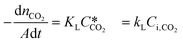 | (3) |
where KL is the overall mass transfer coefficient,  is the equilibrium concentration in the liquid phase corresponding to the CO2 concentration in the gas phase, kL is the liquid film mass transfer coefficient, and Ci,CO2 is the interfacial concentration of CO2.
  can be obtained using Henry's law:
| |  | (4) |
Here, pCO2 is the partial pressure of CO2 in the gas mixture, which is expressed as:
| | 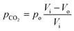 | (5) |
Combining eqn (3)–(5) yields:
| | 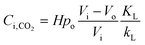 | (6) |
Further, kL is related to the mass transfer coefficient of physical absorption, kL0:
Here, E is a factor representing the intensification effect of the chemical reaction on the mass transfer. The Hatta number, Ha, denotes the ratio of the maximum chemical reaction rate to the maximum mass transfer rate in the liquid film.34
| |  | (8) |
Here, DCO2 is the diffusion coefficient of CO2 in the liquid and k0 is the kinetic constant of a pseudo-first-order reaction between CO2 and MEA (k0 = 577 s−1 for 5 wt% MEA and 4192 s−1 for 15 wt% MEA).35 The reaction rate, rCO2, is written as:
For a fast reaction, E is approximately equal to Ha.34 Thus, kL can be obtained using:
| |  | (10) |
Using eqn (6) and (10) along with the known KL value from Fig. 5, the interfacial concentrations of CO2 were obtained. Fig. 7a shows that the surface tension decreases with increasing Ci,CO2, as was expected. Additionally, using the Langmuir–Szyszkowski equation, which describes the variation of the surface tension of a solution with inconsistent interfacial concentrations,36 a correlated relationship for the dynamic surface tension and Ci,CO2 was found workable for all CO2 and MEA concentrations in this study, as shown in eqn (11) and Fig. 7b:
| | 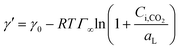 | (11) |
where
Γ∞ is the saturated surface concentration of CO
2 equal to 4.0 × 10
−7 mol m
−2 at
T = 301 K and
aL is the Langmuir parameter (the concentration in the liquid phase at half-surface coverage) equal to 0.0204 mol m
−3. Because CO
2 is not a surface-active substance and is difficult to enrich at the interface, the value of
Γ∞ is about 10 times lower and
aL is 10–100 times higher than those for common surfactants.
20 These results indicate that the dynamic surface tension in gas–liquid absorption is different from that in liquid–liquid emulsification. Although the effect of temperature was not tested experimentally in this study to prevent strong H
2O evaporation,
eqn (11) can still be used to guide the evolution of surface tension at room temperature, if the CO
2 interfacial concentration is measurable. In addition, this equation can also be applied to evaluate the CO
2 interfacial concentration by directly measuring surface tension, which will be helpful in analyzing the mass transfer resistance in other CO
2 absorption processes.
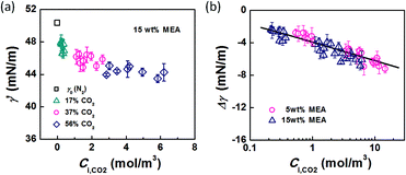 |
| | Fig. 7 (a) Dynamic surface tension versus CO2 interfacial concentration. Data from the 15 wt% MEA experiment is shown as an example. (b) Comparison of surface tension differences (Δγ = γ′ − γ0) with experimental results. The solid line represents eqn (11). | |
Conclusions
The dynamic surface tensions in CO2 absorption processes were studied using a microflow interfacial tensiometer. Based on the scaling law for the bubble diameter, the surface tension at the bubble rupturing moments was confirmed. Their values decreased with an increase in the CO2 mass transfer coefficient and a decrease in the MEA concentration in the liquid phase. The changes in the surface tension were attributed to the varied CO2 concentration in the interfacial layer, which changed the attractive forces between liquid molecules. A relationship between the dynamic surface tension and the interfacial CO2 concentration was established, which indicated different parameters for the Langmuir–Szyszkowski equation from those for common liquid–liquid emulsification which also has dynamic interfacial tension problems. This work clarified the effects of the mass transfer and chemical reaction in gas–liquid absorption on an important fluid dynamics parameter. Theoretical analysis and simulation of the evolution of the interfacial layer will be carried out as a next step.
Acknowledgements
We gratefully acknowledge the support of the National Natural Science Foundation of China (91334201) and the Foundation for the Author of National Excellent Doctoral Dissertation of the People's Republic of China (FANEDD 201349).
References
- D. Voicu, M. Abolhasani, R. Choueiri, G. Lestari, C. Seiler, G. Menard, J. Greener, A. Guenther, D. W. Stephan and E. Kumacheva, J. Am. Chem. Soc., 2014, 136, 3875 CrossRef CAS PubMed.
- M. Zanfir, A. Gavriilidis, C. Wille and V. Hessel, Ind. Eng. Chem. Res., 2005, 44, 1742 CrossRef CAS.
- V. van Steijn, C. R. Kleijn and M. T. Kreutzer, Lab Chip, 2010, 10, 2513 RSC.
- C. Q. Yao, Z. Y. Dong, Y. C. Zhao and G. W. Chen, Chem. Eng. Sci., 2014, 112, 15 CrossRef CAS.
- J. H. Xu, S. W. Li, Y. J. Wang and G. S. Luo, Appl. Phys. Lett., 2006, 88, 133506 CrossRef.
- V. van Steijn, C. R. Kleijn and M. T. Kreutzer, Lab Chip, 2010, 10, 2513 RSC.
- T. Ward, M. Faivre and H. A. Stone, Langmuir, 2010, 26, 9233 CrossRef CAS PubMed.
- X. Wang, G. Liu, K. Wang and G. Luo, Microfluid. Nanofluid., 2015, 19, 757 CrossRef.
- C. M. Phan, T. N. Le and S. Yusa, Colloids Surf., A, 2012, 406, 24 CrossRef CAS.
- N. S. Bhole, F. Huang and C. Maldarelli, Langmuir, 2010, 26, 15761 CrossRef CAS PubMed.
- M. Corti, M. Pannuzzo and A. Raudino, Langmuir, 2015, 31, 6277 CrossRef CAS PubMed.
- U. Teipel and N. Aksel, Chem. Eng. Technol., 2001, 24, 393 CrossRef CAS.
- J. D. Martin and S. D. Hudson, New J. Phys., 2009, 11, 115005 CrossRef.
- J. D. Martin, J. N. Marhefka, K. B. Migler and S. D. Hudson, Adv. Mater., 2011, 23, 426 CrossRef CAS PubMed.
- A. Gunther and K. F. Jensen, Lab Chip, 2006, 6, 1487 RSC.
- J. T. Cabral and S. D. Hudson, Lab Chip, 2006, 6, 427 RSC.
- Q. Brosseau, J. Vrignon and J. Baret, Soft Matter, 2014, 10, 3066 RSC.
- T. Glawdel and C. L. Ren, Phys. Rev. E: Stat., Nonlinear, Soft Matter Phys., 2012, 86, 26308 CrossRef PubMed.
- C. P. Tostado, J. H. Xu, A. W. Du and G. S. Luo, Langmuir, 2012, 28, 3120 CrossRef CAS PubMed.
- K. Wang, L. Zhang, W. Zhang and G. Luo, Langmuir, 2016, 32, 3174 CrossRef CAS PubMed.
- N. R. Beer, K. A. Rose and I. M. Kennedy, Lab Chip, 2009, 9, 838 RSC.
- K. Wang, Y. C. Lu, J. H. Xu and G. S. Luo, Langmuir, 2009, 25, 2153 CrossRef CAS PubMed.
- W. J. Lan, C. Wang, X. Q. Guo, S. W. Li and G. S. Luo, AIChE J., 2016, 62, 2542 CrossRef CAS.
- J. Tan, H. W. Shao, J. H. Xu, L. Du and G. S. Luo, Ind. Eng. Chem. Res., 2011, 50, 3966 CrossRef CAS.
- J. Yue, G. W. Chen, Q. Yuan, L. G. Luo and Y. Gonthier, Chem. Eng. Sci., 2007, 62, 2096 CrossRef CAS.
- J. Yue, G. W. Chen and Q. Yuan, Chem. Eng. J., 2004, 102, 11 CrossRef CAS.
- L. Dubois and D. Thomas, Chem. Eng. Technol., 2009, 32, 710 CrossRef CAS.
- C. X. Zhao and A. Middelberg, Chem. Eng. Sci., 2011, 66, 1394 CrossRef CAS.
- S. L. Anna, Annu. Rev. Fluid Mech., 2016, 48, 285 CrossRef.
- K. Wang, L. S. Xie, Y. C. Lu and G. S. Luo, Chem. Eng. Sci., 2013, 100, 486 CrossRef CAS.
- O. Amyot and F. Plouraboue, Phys. Fluids, 2007, 19, 033101 CrossRef.
- L. Yang, J. Tan, K. Wang and G. Luo, Chem. Eng. Sci., 2014, 109, 306 CrossRef CAS.
- X. Gui, Z. G. Tang and W. Y. Fei, J. Chem. Eng. Data, 2011, 56, 2420 CrossRef CAS.
- C. Alvarezfuster, N. Midoux, A. Laurent and J. C. Charpentier, Chem. Eng. Sci., 1981, 36, 1513 CrossRef CAS.
- S. W. Park, J. W. Lee, B. S. Choi and J. W. Lee, J. Ind. Eng. Chem., 2005, 11, 202 CAS.
- U. Teipel and N. Aksel, Chem. Eng. Technol., 2001, 24, 393 CrossRef CAS.
Footnote |
| † Current address: Department of Mechanical Engineering, School of Engineering, Tokyo Institute of Technology, 2-12-1 Ookayama, Meguro-ku, Tokyo, 152-8550 Japan; E-mail: ylyoro@126.com |
|
| This journal is © The Royal Society of Chemistry 2017 |

 *a and
Guangsheng
Luo
*a
*a and
Guangsheng
Luo
*a


 and Ci,CO2, respectively:
 is the equilibrium concentration in the liquid phase corresponding to the CO2 concentration in the gas phase, kL is the liquid film mass transfer coefficient, and Ci,CO2 is the interfacial concentration of CO2.
  can be obtained using Henry's law:


