 Open Access Article
Development of a fiber-based membraneless hydrogen peroxide fuel cell†
Mohsen Asadnia *a,
Seyyed Mohsen Mousavi Ehteshamib,
Siew Hwa Chanb and
Majid Ebrahmi Warkianic
aDepartment of Engineering, Macquarie University, Sydney, Australia 2109. E-mail: mohsen.asadnia@mq.edu.au; Tel: +61-405459781
bEnergy Research Institute at Nanyang Technological University, CleanTech One, Singapore 637141
cSchool of Biomedical Engineering, University of Technology Sydney, 2007 Australia
First published on 21st August 2017
Abstract
In this paper, polyvinylidene fluoride (PVDF) nanofibers have been suggested as a viable substrate for flexible and implantable electrochemical devices. PVDF electrospun nanofibers exhibit excellent mechanical properties, flexibility, chemical stability, and biocompatibility, making them a potential option in the development of implant fuel cells. This paper presents a membraneless hydrogen peroxide fuel cell that is fabricated to demonstrate the possibility of using these nanofibers as the substrate for electrochemical devices. An open circuit potential of 0.65 V was achieved for the cell fabricated using Prussian Blue (PB) as the cathode material and nickel and aluminium as the anode materials. The power produced by the cell was ∼1 mW cm−2 at 0.32 V. The results presented compare favourably with available power generators reviewed in the literature. Based on the proof of concept demonstration; PVDF electrospun nanofibers can be successfully used for implantable electrochemical devices such as bio-fuel cells and self-sustained point-of-care diagnostic systems.
1. Introduction
The application of flexible and conformable substrate technologies has increased in electronics fabrication over the last decade.1 One of the main issues associated with the design of flexible devices is the mechanical strength of the components including the substrate, which are subjected to varying types of stress such as bending and stretching. An effective approach to mitigate the mechanical strength issue is to lower the substrate thickness, decreasing the stress during different loading steps.2,3The material options for the substrate in flexible devices can be classified into two groups:
(1) semi-natural/semi synthetic substrates – such as paper.
(2) Biocompatible substrates – such as synthetic polymers and silk.
Paper is a semi-natural (cellulose-fiber based)/semi synthetic (synthetic latex binder) substrate.4,5 It may not be considered as a biocompatible substrate but known as a natural material in most of the related studies conducted in the past.4,6 However, being cost-effective, lightweight, environmentally friendly and abundantly available; paper has been widely used for the fabrication of flexible devices such as biosensors, batteries and super-capacitors.6–8
In order to integrate the flexible device within a living body, selecting biocompatible materials for device fabrication is an inevitable and crucial step. Low density polyethylene (LDPE), polyvinyl alcohol (PVA), and poly-dimethyl siloxane (PDMS) are promising options for implantable applications as they have excellent biocompatibility and inflammatory resistance.9–13 PVA as a soluble polymer acts as a sacrificial substrate enabling the control of the transport and mounting of implantable devices.13 The main challenge in the development of implantable materials is to ensure that no foreign-body reaction will take place. This reaction between the tissue and the device leads to the creation of a dense mass covering the device, thus hindering the species transport between the device and the tissue.14 A possible solution is using zwitterionic hydrogels based on poly(carboxybetaine methacrylate) (PCBMA) prepared from a carboxy-betaine monomer (CBMA) and a carboxybetaine cross-linker (CBMAX) aiding species transport between the living tissue and the device.15 However, the issue of a dense mass forming still remains.
During the last decade, interest in PVDF nano-fiber and its applications has grown significantly, particularly in the fields of energy harvesting,16 tissue engineering,17 and sensors.18 PVDF material has been suggested for fabrication of fuel cells in the past. In particular, it is shown that the blend composed of PVDF with high conductive poly(1,4-phenylene ether-ether-sulfone) (SPEES)19 or polyethylene terephthalate (PET)20 conductive carbon black powder led to the lowest through-plane resistivity values. PVDF exhibits notable electrical and mechanical characteristics such as piezoelectricity (highest amount for synthetic polymers), elasticity, flexibility, and biocompatibility.21,22 These notable characteristics make PVDF electrospun nanofibers a desired material for fabricating biocompatible and implantable fuel cells to be used as a source of power inside the body. It is reported that devices made from mono-filament PVDF show a favourable foreign body reaction with small granuloma sizes and CTI length in comparison to available sutures.23,24
In this study, we introduce PVDF electrospun nanofibers for the first time as the substrate for a wearable or implantable electrochemical fuel cell. To prove this concept, a hydrogen peroxide fuel cell with electrospun PVDF nanofibers as the substrate is developed. In the proposed cell, Prussian Blue (PB) was use as the cathode and nickel and aluminium were used as the anode.
2. Experimental
2.1 Fabrication and characterisation of PVDF electrospun nano-fiber
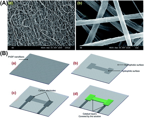
PVDF is a semi-crystalline polymer with a structure comprising of linear chains with hydrogen and fluoride in sequence around a carbon backbone, with a chemical formula (CH2–CF2); this structure is similar to the chemical composition of both polytetrafluoroethylene (PTFE) (CF2–CF2) and ethylene (CH2–CH2). The structural similarity to ethylene gives PVDF its flexibility and the crystalline similarity with PTFE gives PVDF a stereochemical constraint. In this study, the Far Field Electrospinning (FFE) process was used with a rotating collector to achieve aligned PVDF nanofibers; these aligned nanofibers are essential as they enhance the species transport on the surface and lower the concentration loses of the fuel cell. By optimising various electrospinning parameters, we have been able to achieve PVDF nanofibers with the minimum amount of beads as well as successfully obtaining single fibers on differing substrates, which is necessary to characterise the mechanical properties of the fibers. The average diameter of the nanofibers achieved is 800 nm (Fig. 1A-a). SEM images of the randomly oriented and aligned PVDF nanofibers is shown in Fig. 1A-b.2.2 Fabrication of PVDF nanofiber based fuel cell
The PVDF powder (MW 534000) used in the fabrication process was purchased from Sigma-Aldrich. For each electrospinning process, 1.7 g of PVDF powder was dissolved in a mixture of DMF (3.5 ml) and acetone (8 ml) (both also purchased from Sigma-Aldrich) and heated at 40 °C for 120 minutes to creates a homogeneous solution. The resulting transparent viscous solution was transferred into a 10 ml syringe for electrospinning. A 12 kV DC (direct current) voltage was applied across an 18-gauge syringe needle and a rotating spindle which was 10 cm in diameter. The polymer solution was then dispensed at a feed rate of 5 μl min−1. A number of pillar bundle sensors were mounted on the spindle collector which was positioned 15 cm away from the needle. The spindle rotated at a speed of 1500 rpm causing the fibers to stretch as they were deposited on the PDMS pillars while also being electrostatically aligned across the electrode gap.Liquid crystal polymer (LCP) was used as a flexible substrate, which consists of aligned molecule chains with crystal-like spatial regularity. Belonging to a class of aromatic thermoplastic polymers, LCP features a well-ordered structural configuration in both liquid and solid states. In the liquid crystal state, crystal-like regularities are formed as rigid segments of the molecules align next to one another in the direction of the shear flow; this structure remains even after cooling below the melting point.25,26
LCP possesses superior electrical and mechanical properties and features a relative dielectric constant of 3 in the range from 0.5 to 40 GHz and a low loss factor of about 0.004.27 The tensile modulus and tensile strength of LCP exists in ranges of 10 to 24 GPa, and 125 to 255 MPa respectively. LCP is also a hermetic material with a very low moisture absorption (0.02%) and permeability27 and is chemically inert to a number of chemicals, including acids and solvents. In addition, it is also fire resistant and produces relatively non-toxic combustion by-products.27
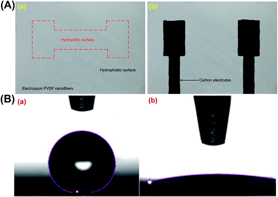
The fabrication process of the proposed fuel cell is depicted in Fig. 1B. First, the aligned PVDF nanofibers are collected on an aluminium foil and then carefully transferred to a flexible LCP substrate with dimensions 25 μm in thickness, 25 mm in width, and 25 mm in length (Fig. 1B-a). PVDF nanofibers after electrospinning exhibit super-hydrophobic behaviour (contact angle of 162°). An oxygen plasma treatment was used for approximately 120 seconds to selectively modify the surface properties of the nanofibers to make them hydrophilic (contact angle of 10°). The hydrophilic pattern enables proper contact between the electrolyte solution and the substrate. Furthermore, as the hydrophilic region is bound by the hydrophobic surface of the substrate, the spillage of the solution is prevented (Fig. 1B-b). Electrodes are created by printing the carbon ink onto the substrate (Fig. 1B-c); the carbon ink was purchased from SPI Supplies (US). Prussian Blue (PB) and aluminium/nickel slurry was used as anode and cathode (Fig. 1B-d). The area shown by red line is the hydrophilic surface and the rest is hydrophobic. Fig. 2A shows the device after creating the carbon ink electrodes. Fig. 2B shows the contact angle of the water on the electrospun PVDF nanofibers before and after surface treatment process.
The anode and cathode catalysts were coated on the carbon electrodes. The ink was prepared by mixing a calculated amount of catalyst with isopropanol alcohol and Nafion solution in an ultrasonic mixer. The area of the catalyzed electrode was 0.1 cm2. Both electrodes were covered by the solution which was half a milliliter electrolyte having H2O2 in 0.1 M hydrochloric acid solution.
2.3 Electrochemical experiments
Eqn (1) and (2) present the overall redox reactions taking place at catalyst layers.28| Al + H2O2 + 2H+ → Al3++ 2H2O + e−; E0 = 3.43 V vs. SHE | (1) |
| H2O2 → 2H2O + O2; E0 = 1.09 V vs. SHE | (2) |
Electrochemical experiments were conducted using Solartron Analytical potentiostat, (Solartron Group Limited, UK) with potential scanning rate and potential step of 20 mV s−1 and 20 mV, respectively. All the experiments were carried out at room temperature.
3. Results and discussion
3.1 Mechanical properties of a single PVDF nanofiber
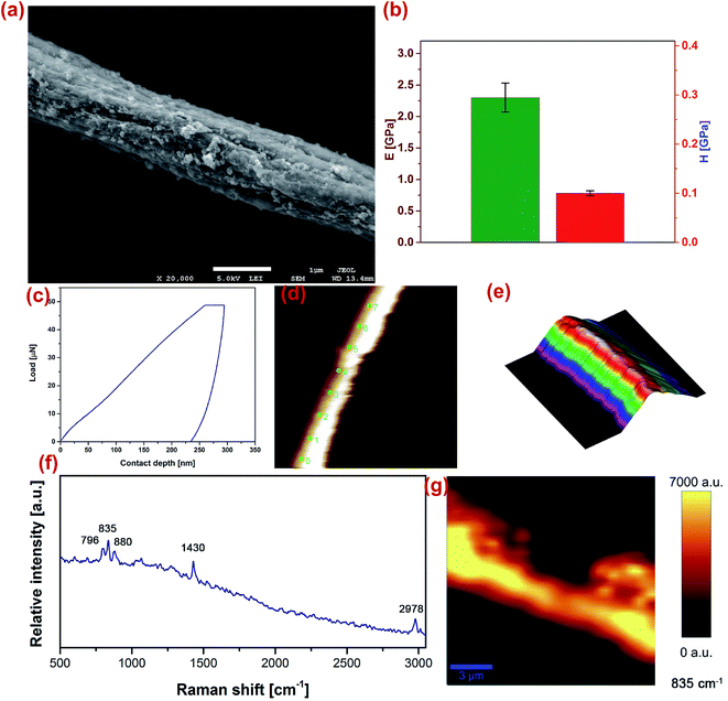
To ensure that mechanical properties of PVDF nanofibers met the requirements of materials for applications in implantable power generators, we have used a nano-indentation analysis to investigate the elastic modulus and hardness of a single PVDF nanofiber. The mechanical properties of the fibers were probed using a TriboScan 950 (Hysitron, MN, USA). The machine was equipped with a cube corner tip and the test was completed in ‘scanning probe microscope’ (SPM) mode. The obtained results are presented in Fig. 3. Due to the sample size, a 50 μN load with 5s–2s–5s load function (loading–holding–unloading) was applied to the samples in piezo-automation mode. Indentation points were chosen on the apex of the fibers. The cube corner tip was calibrated with a standard fused quartz sample for contact depths ranging from 100–400 nm. The nano-indentation studies revealed that the elastic modulus of the fibers were 2.2 GPa and the harness of the samples to be 0.1 GPa. The structural properties of the fibres are investigated by a confocal Raman (Witec, Alpha 300) equipped with a 633 nm wavelength laser and a 50× magnification objective lens for in grating 600 for Raman shifts 500–3000 cm−1. The machine is calibrated using a silicon wafer. The spectra collected are smoothed and filtered using Witec Project 2.04. Fig. 3(f and g) illustrate the Raman spectroscopy experiments on a PVDF single fiber.3.2 Electrochemical characterisation
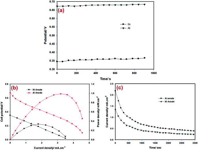
An open-circuit potential of the fabricated cells was recorded for about 15 minutes before conducting further experiments. Fig. 4a presents the open-circuit potential of the cells. Linear sweep voltammetry was used to measure the potential versus current characteristics of the cells. The catalyst regions of the cell were surrounded by a suitable amount of solution.As shown in Fig. 4b, the maximum power density of 1 mW cm−2 is achieved for a cell operating on 0.5 M solution at the cell potential of 0.32 V when aluminium is used as the anode material. The cell with Ni as the anode material produced a maximum power density of ca. 0.33 mW cm−2 at the cell potential of 0.2 V. To the best of our knowledge, the results in this study are the best among the reported results of fuel cells available in the literature.5 The power densities obtained are eight times higher compared to the highest power density obtained in bio-fuel cells reported.29 Results of this study are comparable with those from a previous study where filter paper was used as the substrate.5 An advantage of the current cell is the biocompatibility of the device which makes it desirable as a bio-fuel cell.
Chronoamperometry tests were carried out on cells to study the durability of the performance. As shown in Fig. 4c, the current–time profile of both cells was similar. The drop in the current density over time is attributed to the consumption of H2O2, catalysts degradation and the losses due to mass transport. Parasitic reactions such as hydrogen peroxide decomposition are the causes of bubbles formed around the electrodes. Various measures could be taken to improve the cell performance such as using electro-catalysts with improved activity and stability and/or improving the species transport by optimising the porosity of the fibers.
4. Conclusion
The introduction of PVDF nanofibers fabricated by electrospinning as the substrate for wearable or implantable electrochemical devices was suggested for the first time. In the study, a hydrogen peroxide fuel cell is made to demonstrate the possibility of using PVDF nanofibers as the substrate. The fabrication process consisted of creating patterns on a PVDF electrospun nanofiber substrate using oxygen plasma to define the hydrophobic and hydrophilic surfaces. Aluminium and nickel were used as the anode catalyst and PB was applied as the cathode catalyst. The power produced by the cells was 1 mW cm−2 at 0.32 V and 0.33 mW cm−2 at 0.2 V, for Al and Ni, respectively. Power densities obtained are the highest among available bio-power generators. The cell performance was limited mostly due to species transport. Approaches were suggested to improve cell performance and the mitigation of cell degradation. The nanofiber-based “green” cell is environmentally friendly, flexible, biocompatible and cost effective. It can potentially integrate within a self-sustained point-of-care diagnostic system to provide the on-demand power for biological sensing applications.Conflicts of interest
The authors declare that they have no conflict of interest.Acknowledgements
The authors would like to thank the financial support from Energy Research Institute at Nanyang Technological University, Singapore.References
- V. Misra, A. Bozkurt, B. Calhoun, T. Jackson, J. Jur, J. Lach, B. Lee, J. Muth, O. Oralkan, M. Ozturk, S. Trolier-Mckinstry, D. Vashaee, D. Wentzloff and Y. Zhu, Proc. IEEE, 2015, 103, 665–681 CrossRef CAS.
- M. Kaltenbrunner, M. S. White, E. D. Głowacki, T. Sekitani, T. Someya, N. S. Sariciftci and S. Bauer, Nat. Commun., 2012, 3, 770 CrossRef PubMed.
- Y. J. Park, S. K. Lee, M. S. Kim, H. Kim and J. H. Ahn, ACS Nano, 2014, 8, 7655–7662 CrossRef CAS PubMed.
- M. Irimia-Vladu, Chem. Soc. Rev., 2014, 43, 588–610 RSC.
- S. M. Mousavi Ehteshami, M. Asadnia, S. N. Tan and S. H. Chan, J. Power Sources, 2016, 301, 392–395 CrossRef CAS.
- L. Nyholm, G. Nyström, A. Mihranyan and M. Strømme, Adv. Mater., 2011, 23, 3751–3769 CAS.
- R. Dahiya, M. M. Tentezeris, Z. Cui and M. Singh, IEEE Sens. J., 2015, 15, 3093 CrossRef.
- D. Tobjörk and R. Österbacka, Adv. Mater., 2011, 23, 1935–1961 CrossRef PubMed.
- M. C. Bélanger and Y. Marois, J. Biomed. Mater. Res., 2001, 58, 467–477 CrossRef PubMed.
- M. Rafeie, M. Welleweerd, A. Hassanzadeh-Barforoushi, M. Asadnia, W. Olthuis and M. E. Warkiani, Biomicrofluidics, 2017, 11, 014108 CrossRef PubMed.
- J. W. Tsai, J. J. Wang and Y. C. Su, Sens. Actuators, A, 2014, 215, 176–183 CrossRef CAS.
- G. S. Prihandana, H. Ito, K. Tanimura, H. Yagi, Y. Hori, O. Soykan, R. Sudo and N. Miki, J. Biomed. Mater. Res., Part B, 2015, 103(6), 1180–1187 CrossRef CAS PubMed.
- D. H. Kim, N. Lu, R. Ma, Y. S. Kim, R. H. Kim, S. Wang, J. Wu, S. M. Won, H. Tao, A. Islam, K. J. Yu, T. I. Kim, R. Chowdhury, M. Ying, L. Xu, M. Li, H. J. Chung, H. Keum, M. McCormick, P. Liu, Y. W. Zhang, F. G. Omenetto, Y. Huang, T. Coleman and J. A. Rogers, Science, 2011, 333, 838–843 CrossRef CAS PubMed.
- Y. Onuki, U. Bhardwaj, F. Papadimitrakopoulos and D. J. Burgess, J. Diabetes Sci. Technol., 2008, 2, 1003–1015 CrossRef PubMed.
- L. Zhang, Z. Cao, T. Bai, L. Carr, J. R. Ella-Menye, C. Irvin, B. D. Ratner and S. Jiang, Nat. Biotechnol., 2013, 31, 553–556 CrossRef CAS PubMed.
- C. Chang, V. H. Tran, J. Wang, Y.-K. Fuh and L. Lin, Nano Lett., 2010, 10, 726–731 CrossRef CAS PubMed.
- Y.-F. Goh, I. Shakir and R. Hussain, J. Mater. Sci., 2013, 48, 3027–3054 CrossRef CAS.
- D. Mandal, S. Yoon and K. J. Kim, Macromol. Rapid Commun., 2011, 32, 831–837 CrossRef CAS PubMed.
- E. E. Unveren, T. Y. Inan and S. S. Celebi, Fuel Cells, 2013, 13, 862–872 CAS.
- L. Nguyen, F. Mighri, Y. Deyrail and S. Elkoun, Fuel Cells, 2010, 10, 938–948 CrossRef CAS.
- J. Chang, M. Domnner, C. Chang and L. Lin, Nano Energy, 2012, 1, 356–371 CrossRef CAS.
- M. Asadnia, A. G. P. Kottapalli, K. D. Karavitaki, M. E. Warkiani, J. Miao, D. P. Corey and M. Triantafyllou, Sci. Rep., 2016, 6, 32955 CrossRef CAS PubMed.
- A. Lambertz, K. M. Schröder, D. S. Schöb, M. Binnebösel, M. Anurov, U. Klinge, U. P. Neumann and C. D. Klink, Eur. Surg. Res., 2015, 55(1–2), 1–11 CrossRef CAS PubMed.
- C. D. Klink, K. Junge, M. Binnebösel, H. P. Alizai, J. Otto, U. P. Neumann and U. Klinge, J. Investig. Surg., 2011, 24, 292–299 CrossRef CAS PubMed.
- A. G. P. Kottapalli, M. Asadnia, J. M. Miao, G. Barbastathis and M. S. Triantafyllou, Smart Mater. Struct., 2012, 21, 8 CrossRef.
- A. G. P. Kottapalli, C. W. Tan, M. Olfatnia, J. M. Miao, G. Barbastathis and M. Triantafyllou, J. Micromech. Microeng., 2011, 21, 085006 CrossRef.
- X. F. Wang, J. Engel and C. Liu, J. Micromech. Microeng., 2003, 13, 628–633 CrossRef CAS.
- Y. Yamada, S. Yoshida, T. Honda and S. Fukuzumi, Energy Environ. Sci., 2011, 4, 2822–2825 CAS.
- I. Shitanda, S. Kato, Y. Hoshi, M. Itagaki and S. Tsujimura, Chem. Commun., 2013, 49, 11110–11112 RSC.
Footnote |
| † Electronic supplementary information (ESI) available. See DOI: 10.1039/c7ra08333e |
| This journal is © The Royal Society of Chemistry 2017 |


