DOI:
10.1039/C7RA03504G
(Paper)
RSC Adv., 2017,
7, 29240-29254
Experimental study on the thermal expansion property and mechanical performance of oil well cement with carbonaceous admixtures
Received
26th March 2017
, Accepted 22nd May 2017
First published on 5th June 2017
Abstract
Thermal stress is induced by the mismatch in the thermal expansion properties of a cement sheath and casing steel, which could lead to the generation of microannulus or cracks when the temperature rapidly increases or decreases in a thermal recovery well. This stress can be relieved if the set cement has a coefficient of thermal expansion (CTE) similar to that of the casing steel. In this study, the influence of two carbonaceous admixtures (petroleum coke and gilsonite) on the thermal expansion property, compressive strength, and microstructure of the oil well cement were studied. Experimental results show that replacing the cement with different proportions of carbonaceous admixtures increases the CTE of the set cement. This effect is mainly attributed to not only the improvement in the cement microstructure as a result of the filling effect but also the thermal pressurization caused by the expansion of the volatile matter in carbonaceous admixtures and the phase transition of the gilsonite particles in the cement paste when the temperature rapidly increases. Furthermore, the transformation of the hydrate products narrows the CTE range of the hardened cement paste when the cement is subjected to a high temperature history. Although the addition of carbonaceous admixtures has a negative influence on the strength performance of the set cement, it still satisfies the needs of cementing engineering and guarantees the cementing quality.
1. Introduction
Heavy oil is an important part of the world energy structure and it is attracting significant interest with the increasing demand for petroleum all over the world. There are abundant heavy oil resources around the world, which have been estimated about 13![[thin space (1/6-em)]](https://www.rsc.org/images/entities/char_2009.gif) 000 billion bbls of heavy oil in 1200 oil deposits.1,2 Considering the heavy oil recovery, the viscosity of heavy oil must be reduced to a value at which it can gain mobility and be produced up to the surface. There are many exploitation methods of heavy oil that include elevation of the oil reservoir temperature and reduction of oil viscosity; however, steam stimulation is the most promising method among all the possible techniques.3 Oil well integrity is an essential and key link for heavy oil development and exploitation. Moreover, cement sheath integrity is crucial for the well integrity and zonal isolation, which prevents undesired fluids such as oil, gas or steam from flowing into the wellbore and supports the wellbore.4 The oil well cement sets at low temperature at the beginning, but then requires high temperatures for a long term period due to the particular extraction method of heavy oil reservoir.2 Chemical stability, mechanical properties, and permeability are commonly the main parameters determined for characterizing the oilfield cement systems.5
000 billion bbls of heavy oil in 1200 oil deposits.1,2 Considering the heavy oil recovery, the viscosity of heavy oil must be reduced to a value at which it can gain mobility and be produced up to the surface. There are many exploitation methods of heavy oil that include elevation of the oil reservoir temperature and reduction of oil viscosity; however, steam stimulation is the most promising method among all the possible techniques.3 Oil well integrity is an essential and key link for heavy oil development and exploitation. Moreover, cement sheath integrity is crucial for the well integrity and zonal isolation, which prevents undesired fluids such as oil, gas or steam from flowing into the wellbore and supports the wellbore.4 The oil well cement sets at low temperature at the beginning, but then requires high temperatures for a long term period due to the particular extraction method of heavy oil reservoir.2 Chemical stability, mechanical properties, and permeability are commonly the main parameters determined for characterizing the oilfield cement systems.5
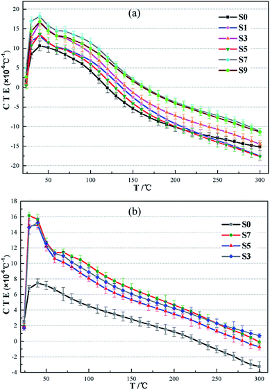
In the course of the thermal production process, steam is injected into the reservoir through the wellbore and heats it up to reduce the viscosity of heavy oil. The temperature of the oil reservoir sometimes increases to 250 °C or even over 300 °C. However, when the temperature is above 110 °C, the C–S–H gel in the cement paste begins to transform into another hydrate product, α dicalcium silicate, which has a denser structure, and leads to an obvious volumetric shrinkage of the cement.6 This transformation of the hydrate products also has an adverse effect on the compressive strength and permeability of the conventional cement. This negative influence can be prevented by mixing a certain amount of fine silica sand or silica flour into oil well cement with the generation of different hydrated calcium silicate products that have better chemical stability at high temperature and prevent strength retrogression of the hardened cement paste.2,7,8 The typical thermal expansion coefficient value of a casing steel is about 13 × 10−6 °C−1 and the thermal expansion coefficient for a conventional oil well cement system is measured to be around 9–10 × 10−6 °C−1 at the water-saturated state,2 which does not appear to be very different from that of the casing steel. However, there are oil–gas layers, water zones, and dry layers in the oil well, and the thermal expansion properties of the cement and casing are quite different at different temperatures under a dry environment. It can be observed from Fig. 1 that the thermal expansion coefficients of the hardened oil well cement and casing steel are not constant values but vary with the test temperature under a dry condition. At the beginning of the test, the CTEs of the two materials increase with the increasing temperature when the test temperature is below 45 °C. After this, the CTE of the casing steel slightly increases, whereas that of the hardened cement gradually decreases as the temperature increases. The value of the CTE of the hardened cement decreases to zero, which means that the hardened cement paste begins to shrink when the test temperature increases to 120 °C. Therefore, in the dry layers, extreme thermal stresses are generated at the interface of the cement sheath and the casing steel and the well should be cooled down to meet the need of the workover treatment and warmed up again to resume thermal recovery. As can be seen in Fig. 2, if the thermal stresses exceed the ultimate tensile strength of the cement sheath around the wellbore, microcracks or even a microannulus will emerge.9–11 As a consequence, the cement sheath integrity could be invalid, which will lead to the failure of well cementing and pose a threat to the efficiency of heavy oil production and the well longevity.12 For conventional cement, the addition of fine silica sand or silica flour can prevent the strength retrogression of the cement sheath that is caused by long-term exposure to the high temperature condition. However, the thermal stresses induced by the incompatibility of the thermal expansion properties between the cement sheath and casing cannot be eliminated during the heating and cooling cycles. Improving the coefficient of thermal expansion (CTE) of the oil well cement by adding different additives is one of the main measures to mitigate this stress in a thermal recovery well. Therefore, the thermal expansion property of cement should also be considered in designing new cement sheaths. During the thermal-recovery process (heating stage), this new cement system will expand as much as the casing, which will reduce the risk of mechanical failure.
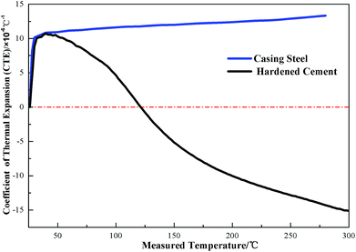 |
| | Fig. 1 The thermal expansion coefficients of the casing steel and set cement under the dry condition. | |
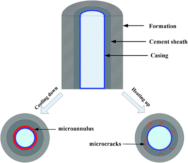 |
| | Fig. 2 The influence of cooling and heating cycle on the cement sheath. | |
For cement-based materials, the coefficient of thermal expansion (CTE) is the main parameter characterizing their thermal expansion properties.13 The CTE of cement is related to the moisture content, internal relative humidity, porosity, and development of the cement hydration products.14–18 In addition, different types of aggregates in the paste can also influence the CTE of cementitious materials. The effects of three types of coarse aggregates, including porous and dense limestone and river gravel, on the linear CTE of the concrete and cement paste have been investigated.19 It was also found that mineral additives, especially for fly ash, silica fume, and blast furnace slag, lowered the CTE of the hardened cement paste because of change in the porosity and transformation of the massive cement hydrates.20 Furthermore, a water-retaining lightweight aggregate is introduced to control the increase in the cement's CTE as a result of its internal curing effect.21 Compared to the detailed studies carried out on controlling the CTE of the hardened cement paste, little attention has been paid to the improvement of the thermal expansion property via increasing its CTE.
Petroleum coke material, which is widely used as an alternative fuel due to its high calorific value in cement kilns or coal-fired power plants, is a solid by-product obtained from oil refining.22,23 Petroleum coke powder is also used as an electrically conductive filler in concrete for deicing through resistance heating24,25 and electromagnetic interference (EMI) shielding.26,27 Furthermore, the use of petroleum coke as an acoustic absorbent material in cement systems has been reported, and satisfying results have been obtained due to its high porosity.28 Gilsonite is a natural and resinous hydrocarbon that is often called natural asphalt or asphaltite. In cementing applications, gilsonite has primarily been used as a lightweight additive due to its low density, chemical inertness, and low water requirements.29–31 Other benefits of the addition of gilsonite include good lost circulation control and the ability of cement to self-heal.30,32 Carbonaceous materials, such as finely ground coke, gilsonite, and petroleum coke, are also effective as extenders for low specific gravity and improve the flexibility of the cement slurries.33–35 The linear thermal-expansion coefficient of the set cement increases with the incorporation of carbonaceous materials when the temperature increases from 20 to 80 °C in a water bath.36 However, the thermal-expansion property of the set cement significantly varies under dry environment and high temperature conditions than under a water-saturated condition. Therefore, the influences of carbonaceous admixtures, including finely ground petroleum coke and gilsonite, on the thermal expansion behavior of the set cement under anhydrous conditions were studied herein. Furthermore, the hydrate products and compressive strength of a new cement system were investigated. Microstructures and pore size distributions of the cement pastes were also observed via scanning electron microscopy and mercury intrusion porosimetry (MIP), respectively, to explain the influencing mechanisms.
2. Materials and methods
2.1 Materials
High sulfate-resistant Class-G oil well cement produced by Shandong ShengWei Enterprise Company was used in the experiments. Silica flour was mixed into the cement system at a concentration of 40% by weight of cement (BWOC) to form the stable phase-xonotlite and prevent recession of the cement strength at high temperature. Micro-silica fume was blended into the cement slurry to limit the sedimentation of the cement system. The typical composition and physical properties of the oil well cement, silica flour, and micro-silica fume are presented in Table 1.
Table 1 Typical composition and physical properties of the raw materials
| Typical mineral composition of Class G oil well cement (wt%) |
| C3S |
C2S |
C4AF |
C3A |
| 52.5 |
31.2 |
7.9 |
2.6 |
| Typical chemical composition (wt%) |
| |
CaO |
SiO2 |
SO3 |
Fe2O3 |
Al2O3 |
MgO |
Na2O |
K2O |
| Cement |
64.20 |
19.40 |
2.80 |
5.50 |
4.50 |
2.00 |
0.10 |
0.60 |
| Silica flour |
0.26 |
98.41 |
0.02 |
0.13 |
0.42 |
0.37 |
0.15 |
0.11 |
| Micro-silica |
2.29 |
94.92 |
0.03 |
0.65 |
0.72 |
0.55 |
0.48 |
0.31 |
| |
Density (g cm−3) |
Specific surface area (m2 g−1) |
Loss on ignition (wt%) |
| Physical properties |
| Cement |
3.16 |
0.336 |
0.48 |
| Silica flour |
2.66 |
0.342 |
0.24 |
| Micro-silica |
1.65 |
21.36 |
0.92 |
A fluid loss control additive (BXF-200L), which is an acrylamide copolymer with salt tolerance and temperature resistance properties obtained from the Company of China National Petroleum Corporation, was used to control the fluid loss of the cement. The dispersant FHJZ-1, which is a polycarboxylate superplasticizer obtained from the Fuhai Industry Development Company, was needed to reduce the friction between cement particles and improve the rheological properties of the cement paste. A defoamer, whose chemical composition was TBP (tributyl phosphate), was also required to eliminate bubbles generated during the mixing process.
Herein, two types of carbonaceous materials, including finely ground petroleum coke and gilsonite, were used in the experiments. Proximate analysis and the typical properties obtained from representative samples are summarized in Table 2. The particle size distributions of the raw materials, including oil well cement, two types of carbonaceous materials, silica flour, and micro-silica, are presented in Fig. 3. The mean and median particle diameter of the raw materials are given in Table 3.
Table 2 Proximate analysis and typical properties of petroleum coke and gilsonite
| Proximate analysis of petroleum coke (wt%) |
| Moisture |
Ash |
Volatile |
Total sulfur |
Fixed carbon |
Specific gravity |
Specific surface area (m2 g−1) |
| 0.15 |
0.22 |
8.99 |
6.24 |
90.64 |
1.11 |
0.438 |
| Typical properties of gilsonite |
| Moisture (wt%) |
Ash (wt%) |
Fixed carbon (wt%) |
Solubility in CS2 (wt%) |
Specific gravity |
Specific surface area (m2 g−1) |
Softening point (°C) |
Flash point (°C) |
| 0.5 |
7.6 |
27.5 |
74.9 |
1.05 |
0.452 |
130 |
500 |
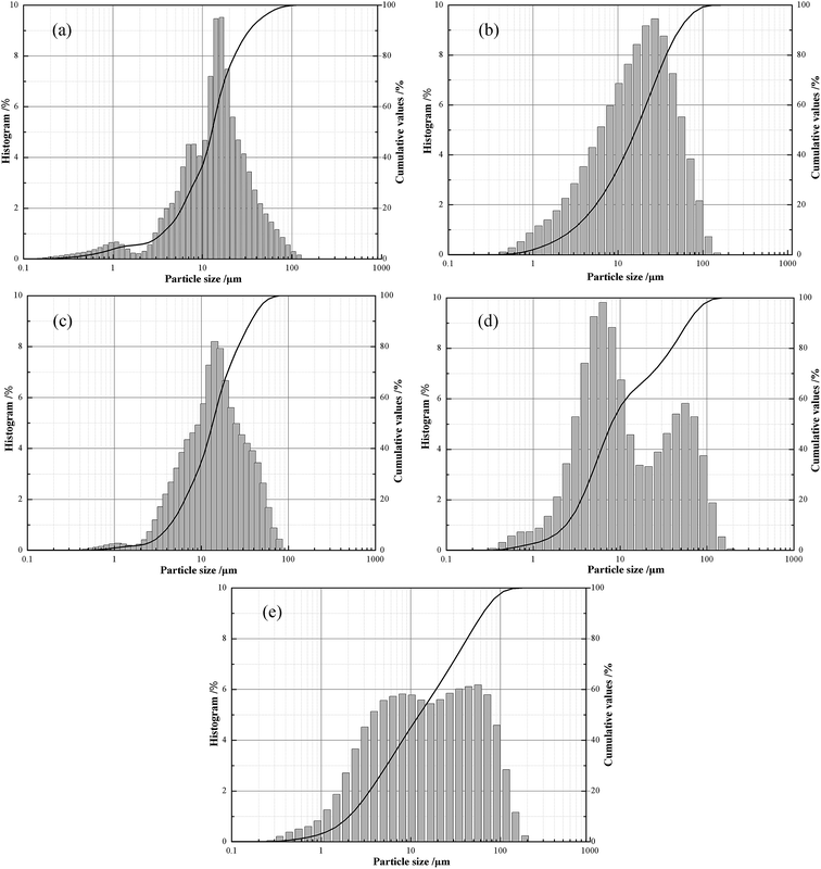 |
| | Fig. 3 Particle size distribution of raw materials. (a) Oil well cement; (b) silica flour; (c) microsilica; (d) gilsonite; and (e) petroleum coke. | |
Table 3 The mean and median particle diameter of raw materials
| Raw materials |
Mean particle diameter (μm) |
Median particle diameter (μm) |
| Cement |
17.14 |
13.40 |
| Silica flour |
21.16 |
13.35 |
| Microsilica |
17.32 |
13.47 |
| Gilsonite |
20.76 |
7.90 |
| Petroleum coke |
25.29 |
12.99 |
Moreover, two experimental parts were designed for the purpose of revealing the influences of the carbonaceous admixtures on the thermal expansion properties and mechanical performance of the oil well cement. First, the influences of two carbonaceous materials on the physical properties of the cement paste were independently studied. Some cement samples, in which S0 was a control group without any carbonaceous admixtures, were prepared and are shown in Table 4. Then, the optimal experiment was designed, as presented in Table 5, to research the combined effect of the finely ground petroleum coke and gilsonite on the thermal expansion performance of cement. The total dosages of the two types of carbonaceous materials did not exceed 50% by weight of the cement as a consequence of their negative impact on the compressive strength performance of the hardened cement paste.
Table 4 Mix proportions of the binder in cement pastes (wt%)
| Samplea |
S/C |
P/C |
G/C |
M/C |
Di/C |
De/C |
F/C |
Density (g cm−3) |
| All cement slurries were prepared with water/solid = 0.5 and the mix proportions were by weight of cement; S, P, G, M, D, De, and F are silicon flour, petroleum coke, gilsonite, micro silicon, dispersant, defoamer, and fluid loss additive, respectively. |
| S0 |
40 |
0 |
0 |
5 |
0.5 |
0.5 |
4 |
1.81 |
| P1 |
40 |
10 |
0 |
5 |
0.5 |
0.5 |
4 |
1.77 |
| P2 |
40 |
20 |
0 |
5 |
0.5 |
0.5 |
4 |
1.72 |
| P3 |
40 |
30 |
0 |
5 |
0.5 |
0.5 |
4 |
1.65 |
| P4 |
40 |
40 |
0 |
5 |
0.5 |
0.5 |
4 |
1.58 |
| P5 |
40 |
50 |
0 |
5 |
0.5 |
0.5 |
4 |
1.52 |
| G1 |
40 |
0 |
5 |
5 |
0.5 |
0.5 |
4 |
1.79 |
| G2 |
40 |
0 |
10 |
5 |
0.5 |
0.5 |
4 |
1.76 |
| G3 |
40 |
0 |
15 |
5 |
0.5 |
0.5 |
4 |
1.72 |
| G4 |
40 |
0 |
20 |
5 |
0.5 |
0.5 |
4 |
1.67 |
Table 5 Optimization of the experimental formula
| Admixtures (wt%) |
Samplea |
| S1 |
S2 |
S3 |
S4 |
S5 |
S6 |
S7 |
S8 |
S9 |
S10 |
| All cement pastes were prepared with water/solid = 0.5 and the same dosages of different additives except for petroleum coke and gilsonite; the mix proportions are by weight of cement. |
| Petroleum coke |
10 |
20 |
30 |
40 |
10 |
20 |
30 |
10 |
20 |
10 |
| Gilsonite |
10 |
10 |
10 |
10 |
20 |
20 |
20 |
30 |
30 |
40 |
| Density (g cm−3) |
1.69 |
1.65 |
1.59 |
1.53 |
1.64 |
1.60 |
1.52 |
1.58 |
1.54 |
1.52 |
2.2 Sample preparation
Class-G oil well cement slurries were prepared in strict accordance with the preparation procedure presented in the API Recommended Practice for Testing Well Cements 10B.37 Experimental formulations of the cement slurries are shown in Tables 3 and 4. First, all the solid materials including Class-G cement, silica flour, and micro-silicon fume were mixed well in a cup. Moreover, the additives, such as dispersant, defoamer, and the fluid loss additive, for cement slurry were dissolved in water and blended well in the cup of the blender. Second, all the solid materials were transferred into the blender cup within 15 s at a stirring rate of 4000 rpm, and then, the slurries were mixed for 35 s at a stirring rate of 12000 rpm. After being mixed well, cement slurries were placed into 50 × 50 × 50 mm cubes for compressive strength test. For measuring the thermal expansion coefficient of the hardened cement pastes, the well-mixed cement slurries were cast into metallic moulds, which could separate the cement paste into 10 × 10 × 50 mm cuboid specimens. After being solidified, the cement specimens were made as standard samples, as presented in Fig. 4, that were used for testing the thermal expansion coefficient.
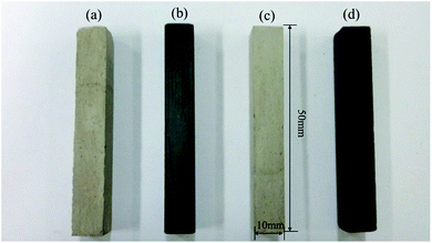 |
| | Fig. 4 Cement specimens for the CTE measurements. (a and c) Control groups and (b and d) cement specimens containing carbonaceous materials obtained after solidification, respectively. | |
2.3 Methods
2.3.1 Compressive strength test. Compressive strength is an important parameter for evaluating the cementing quality in an oil well as excellent compressive strength is conducive for preserving the cement sheath and extending the oil well longevity.38 Considering the complicated conditions in the downhole, temperature and pressure would be important factors affecting the cementing quality.39 In a thermal recovery well, the oil well cement sets at low temperature at the beginning but then works at high temperatures for a long period during the production process. In consideration of this circumstance in the downhole, cement slurries were initially cured at 75 °C at atmospheric pressure for 7 days, and then, these cement pastes were placed into the high temperature curing chamber at a temperature of 200 °C and pressure of 10 MPa for 7 days, which could simulate the downhole condition. After being cured at 75 °C and 200 °C, the cement specimens were placed in a cooling bath, in which the temperature of water was 27 ± 3 °C, for 30 minutes before conducting the compressive strength test, according to the API criterion. Then, three specimens of each kind of hardened cement paste at different temperatures were investigated for the compressive strength, and the average value was obtained as the compressive strength of the cement specimen.
2.3.2 Thermal expansion coefficient measurement. Recently, most of the studies have been focused on the thermal expansion property of the hardened cement paste under the water-saturated condition, and the measured temperature is between 20 and 80 °C.5,18,21 Considering the anhydrous condition in the dry layers and the high temperature in the thermal recovery well, the thermal expansion coefficient of the set cement was measured by a horizontal thermal expansion coefficient dilatometer, and the cement specimens were heated from 24 °C to 300 °C at an increasing rate of 1 °C per minute, allowing the temperature distribution of the specimen to become uniform; then, the CTEs of the specimen at different temperatures were obtained by the computer. The schematic of the experimental setup for the CTE measurements is shown in Fig. 5. To decrease the experimental errors, the thermal expansion coefficient of three specimens of each kind of hardened cement paste were measured, and the average value was obtained as the CTE of each kind of set cement.
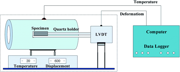 |
| | Fig. 5 Experimental setup for the CTE measurement. | |
Before measuring the CTEs of the hardened cement pastes, the experimental setup must be calibrated. Generally, the thermal expansion coefficient of quartz is considered as a constant value (0.54 × 10⁻⁶ °C−1). Although the CTE of quartz is low, the expansion of the long quartz holder, which supports the cement specimen, cannot be ignored during the measurement. This slight expansion affects the measurement of the total expansion and the expansion of the cement specimen. Therefore, the thermal expansion coefficient of each specimen was calculated using the following formulas:
| | |
αs = εs/ΔT = (ΔLt − ΔLq)/(L0 × ΔT),
| (3) |
where Δ
Lt is the total expansion of the dilatometer; Δ
Ls and Δ
Lq is the expansion of the cement specimen and quartz holder, respectively;
εs and
αs is the thermal strain and CTE of the specimen at a temperature interval, respectively;
L0 is the length of the specimen at 24 °C; and Δ
T is the change in the value of the measured temperature.
2.3.3 X-ray diffraction. X-ray diffraction (XRD) analysis was conducted using a Bruker D8-Advance X-ray diffractometer. The measurement data was obtained within the 10–90° range for the common cement-forming minerals at a grade of 0.02° increment with Cu Kα radiation.
2.3.4 Mercury intrusion porosimetry. Mercury intrusion porosimetry was performed using a Micromeritics AutoPore IV9500 system, and the pore-size distributions of the cement pastes with the addition of carbonaceous admixtures were measured at the age of 7 days. The total porosity was also obtained during the measurement.
2.3.5 Microstructural characterization. Scanning electron microscopy (SEM) was performed on selected samples using a scanning electron microscope ETD to determine the microstructure change of the cement specimen. The EDX spectra were obtained using an OXFORD INCA X-act equipment installed in the same SEM instrument.
3. Results and discussion
3.1 Thermal expansion property
Thermal expansion coefficients (CTEs) of the oil well cement containing two types of carbonaceous materials are presented in Fig. 6–8. It can be observed in Fig. 6 that the thermal expansion coefficients of all the cement pastes vary with the test temperature and the relation between the CTEs and the temperature change is non-linear. The thermal expansion of the hardened cement paste can be seen as a result of the thermal expansion of the solid materials and the dehydration shrinkage of the hydrate products in the cement paste. It is also evident that the CTE of all the samples between 24 and 40 °C increases as the test temperature increases. In fact, when the set cement saturated with water is heated, the liquid phase in the pores expands more than the solid phases.40 During this period, the liquid in the cement paste has no time to flow out of the cement matrix; thus, the liquid expansion results in an increased CTE. When the temperature continued to increase (40–60 °C), a sharp decrease in the CTE was observed. This change is because free water in the cement paste flows out of it and is gradually lost. When the sample is heated above 100 °C, the CTE values rapidly drop, which correspond to the aggravation of water loss in the main hydrate products such as the C–S–H gel. The shrinkage value of the hydrate products due to dehydration is more than the thermal expansion value. As a consequence, it results in a decrease in the hardened cement's CTE.
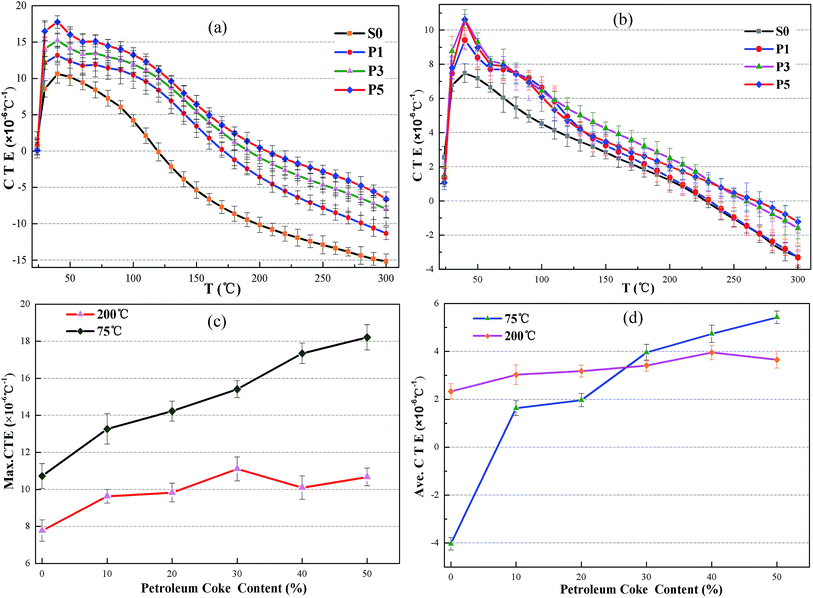 |
| | Fig. 6 Coefficients of thermal expansion of set cements with the addition of petroleum coke. (a) Cement specimens cured at 75 °C; (b) cement specimens cured at 200 °C; (c) the maximum CTE of the specimen; and (d) the average CTE of the specimen. | |
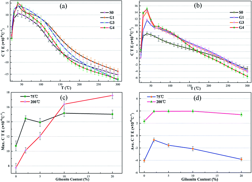 |
| | Fig. 7 Coefficients of thermal expansion of set cements with the addition of gilsonite. | |
 |
| | Fig. 8 Coefficients of thermal expansion of set cements with carbonaceous admixtures. | |
As shown in Fig. 6, on substituting petroleum coke for the oil well cement, the CTE of the hardened cement pastes cured at 75 °C and 200 °C increased. The maximum CTE of the set cement in the control group cured at 75 °C and 200 °C was found to be 10.724 × 10⁻⁶ °C−1 and 7.777 × 10⁻⁶ °C−1, respectively. When the dosage of petroleum coke is 20%, the maximum CTE is 14.231 × 10⁻⁶ °C−1 and 9.829 × 10⁻⁶ °C−1, which is 132.7% and 126.4% that of the control group, respectively. However, the addition of petroleum coke does not significantly change the CTEs of the specimens after being cured at 200 °C. After being exposed to high temperature, the hydrate products of the cement specimen changed, and the added calcium silicate hydrate phase, such as xonotlite (C6S6H), has a compact structure and good thermal stability; this has been explained in Section 3.3. Therefore, the structure and thermal expansion property of the hardened cement were improved and the effect of increasing CTE of petroleum coke was not significant as compared to that of the set cement cured at 75 °C. A similar relation was observed in the average CTEs of the cement specimen, which increased as the content of petroleum coke increased. For the hardened cement with a petroleum coke replacement, the test temperature when the CTE of the hardened cement decreases to zero, which means that the hardened cement begins to shrink, is higher than that of the control group. Therefore, the addition of petroleum coke can also mitigate the shrinkage behavior of the hardened cement paste at high temperatures. However, the increasing effect is limited with the replacement of the oil well cement levels up to 50%.
The effect of gilsonite on the thermal expansion properties of oil well cement is similar to that of petroleum coke. It is also clear in Fig. 7 that the CTE of the hardened cement increases with an increase in the dosage of gilsonite. However, when the test temperature is higher than 200 °C, the CTE of the hardened cement containing gilsonite even more sharply decreases than that of the control group. At 300 °C, the CTE of the hardened cement replaced with 20% gilsonite is lower than that of the control group, which is −17.013 × 10⁻⁶ °C−1 and −15.201 × 10⁻⁶ °C−1, respectively (Fig. 7a).
For the cement specimens containing both carbonaceous admixtures, better thermal behaviors were observed, as shown in Fig. 8. The maximum and average CTE of these specimens are listed in Table 6. The maximum CTE of the hardened cement paste (S7) containing 30% petroleum coke and 20% gilsonite could increase up to 20.613 × 10⁻⁶ °C−1, which was 188.2% that of the control group. The increasing effect is also found in cement specimens at high temperatures. Thus, on partly replacing the cement with petroleum coke and gilsonite, the CTE of the hardened cement paste increased, which was beneficial for the cement sheath and casing to relieve their mismatch phenomenon in terms of thermal expansion property. The increasing effect is directly related to the replacement proportion of carbonaceous admixtures in cement slurries. Even if the average CTE of the set cement increases with the addition of carbonaceous admixtures, it still lags behind that of the casing steel.
Table 6 Max. and Ave. CTE of cement samples containing petroleum coke and gilsonite
| Sample |
Max. CTE (×10−6 °C) |
Ave. CTE (×10−6 °C) |
| 75 °C |
200 °C |
75 °C |
200 °C |
| S0 |
10.955 |
10.955 |
−1.016 |
−1.016 |
| S1 |
14.836 |
12.353 |
0.928 |
2.325 |
| S2 |
14.417 |
14.584 |
1.864 |
4.335 |
| S3 |
17.261 |
17.592 |
2.880 |
6.302 |
| S4 |
16.065 |
17.653 |
5.562 |
7.689 |
| S5 |
14.576 |
17.636 |
1.083 |
5.526 |
| S6 |
17.114 |
18.256 |
1.099 |
6.021 |
| S7 |
20.613 |
19.016 |
5.762 |
6.679 |
| S8 |
20.974 |
19.325 |
1.421 |
3.215 |
| S9 |
18.190 |
20.741 |
4.881 |
5.741 |
| S10 |
16.911 |
16.949 |
5.459 |
6.041 |
Furthermore, when the cement paste is subjected to high temperature, the variation range of its CTE is much smaller than that of the cement cured at 75 °C (Fig. 5b, 6b, and 7b). For the control group S0, the measured CTEs of the hardened cement paste cured at 75 °C are between −16 and 11 × 10−6 °C−1, whereas after the samples are cured at 200 °C, the values are about −4 to 8 × 10⁻⁶ °C−1. This phenomenon can be explained by the change in the hydrate products when the cement specimen is exposed to high temperature.
3.2 Compressive strength
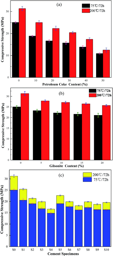
Replacing cement with carbonaceous admixtures has a negative impact on the compressive strength performance of the cement paste. A high compressive strength is essential for an oil well cement sheath to bear the compressive loads induced in the interfaces of casing-cement-formation, support the casing string, and protect the wellbore stability.41 The compressive strength of the hardened pastes with different dosages of petroleum coke and gilsonite were measured after curing the pastes at 75 °C and 200 °C, and the experimental results are shown in Fig. 9.
 |
| | Fig. 9 The compressive strength results of the set cement with carbonaceous materials. | |
It can be seen in Fig. 9 that the control group (S0) has higher compressive strength at both 75 °C and 200 °C than the cement pastes with the carbonaceous admixtures replacement. The compressive strength of the cement specimen decreases with an increase in the petroleum coke and gilsonite content. After being cured at 75 °C, the compressive strength of the cement sample P2 containing 20% petroleum coke and G4 containing 20% gilsonite was 16.65 MPa and 21.13 MPa, which was 66.46% and 84.33% that of the control group, respectively. Carbonaceous admixtures have a significantly adverse impact on the compressive strength of cement pastes because of their physicochemical properties. Petroleum coke is an inert substance that has a porous and loose structure and does not react chemically with cement components. The addition of massive petroleum coke, distributing in the cement slurry, can reduce the structural bonding strength of the cement paste, which results in a negative impact on the compressive strength. Similar to petroleum coke, gilsonite also does not react with any cement components. Although the liquid state of gilsonite can decrease the continuity of the cement matrix at high temperatures, gilsonite will change from a liquid to a solid with a dense and compact structure again at test temperatures (27 ± 3 °C). Therefore, the cement specimen containing gilsonite can still maintain a higher compressive strength than that containing petroleum coke. Moreover, the adverse effect of gilsonite is less attributed to its compact structure. Although the adverse impact of the carbonaceous admixtures on the compressive strength of cement cannot be ignored, the strength value of the cement specimen S7, with 30% petroleum coke and 20% gilsonite, measured after the specimen was cured at 75 °C for 72 h was up to 16.23 MPa, which still satisfied the needs of cementing engineering (13.8 MPa)42 and guaranteed the cementing quality.
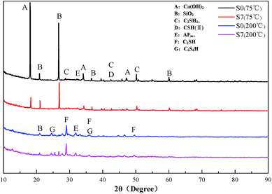
3.3 Phase analysis
S0 and S7 were measured for phase analysis of the cement paste before and after adding the carbonaceous materials, respectively. The XRD patterns of different cement specimens are presented in Fig. 10.
 |
| | Fig. 10 XRD patterns of cement pastes cured at 75 °C and 200 °C. | |
As can be seen in Fig. 10, after the cement specimens were cured at 75 °C and 200 °C, there was no difference in the diffractograms from S0 and S7, which suggested that no new mineral product was generated with the addition of carbonaceous materials. Thus, carbonaceous materials do not chemically react with any cement components. It can be also observed that the main products changed after the cement was subjected to a high temperature history. Cement paste cured at 200 °C showed lower intensity of diffraction lines of calcium hydroxide (CH) and SiO2 and higher intensity of diffraction lines characteristics for C2SH and C6S6H. This is due to the pozzolanic reaction of SiO2 in silicon flour with the CH in cement to form the addition calcium silicate hydrate phase, which can be converted into xonotlite (C6S6H) at high temperature. This product, C6S6H, has a compact structure and good thermal stability, and therefore, it can effectively guarantee the good compressive strength of cement paste. Moreover, the thermal expansion property of hardened cement is also improved, which is the reason why the variation range of CTE is smaller than that of the cement paste after being cured at 75 °C, as shown in Fig. 6–8.
3.4 Pore structure characterization
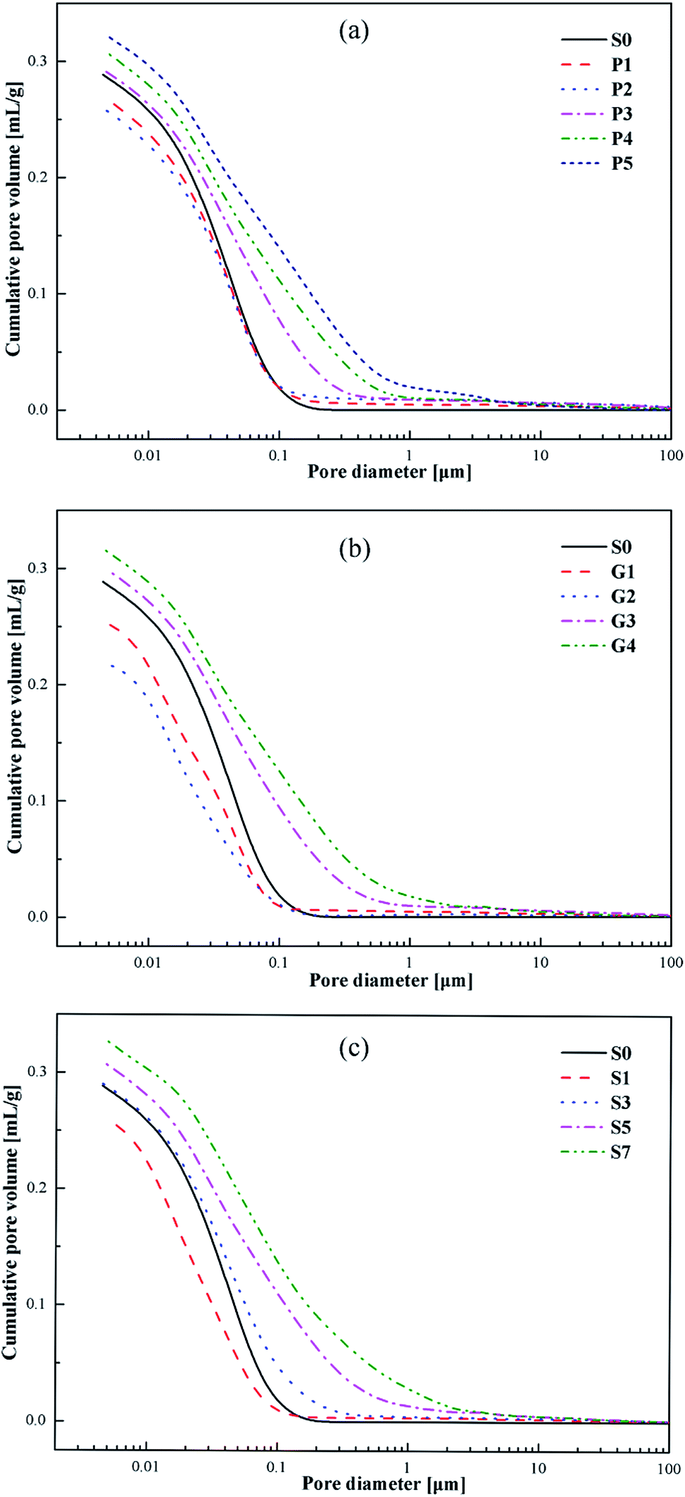
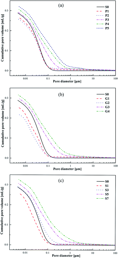
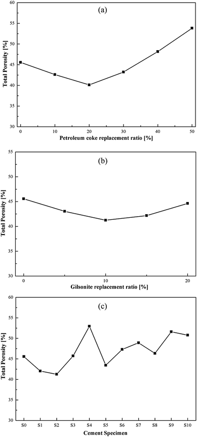
Fig. 11 shows the cumulative pore volumes of the cement specimens. As can be seen in Fig. 11, the addition of carbonaceous admixtures produces different variations in the pore volumes of the cement specimens at the age of 7 days. When the replacement ratio of the carbonaceous admixtures is appropriate, for example 20% of petroleum coke or 10% of gilsonite, the pore volume decreases. However, the pore volumes increase as the replacement ratio of petroleum coke increases up to 30% or the dosage of gilsonite is over 15% or even more, which is consistent with the total porosities of the specimens with different replacement ratios as shown in Fig. 13.
 |
| | Fig. 11 Cumulative pore volumes of the specimens. | |
Fig. 12 shows the differential pore-size distributions of the specimens. All the specimens have differential peaks at the pore diameters in the range of 0.01–1 μm. With the appropriate addition of the carbonaceous admixtures, the pore diameters corresponding to the peaks decrease, indicating a filling effect owing to the carbonaceous admixtures in the cement pastes. However, as the replacement ratio increases, the peaks move to larger pore diameters. Moreover, the number of large and small pores gradually increases and decreases, respectively.
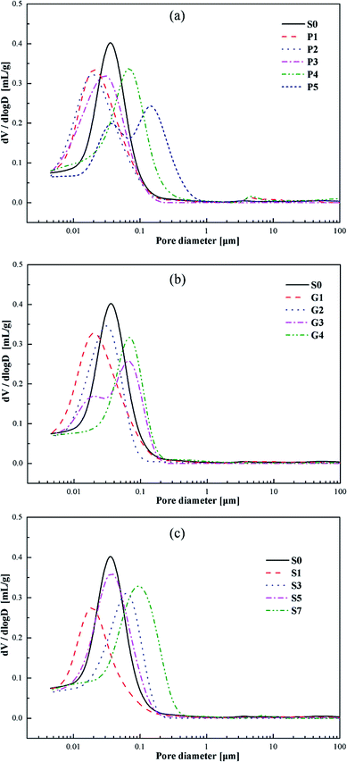 |
| | Fig. 12 Differential pore-size distributions of the specimens. | |
The total porosities of the specimens are presented in Fig. 13. As the replacement ratio of the carbonaceous admixtures increases, the total porosity of the specimen decreases at first and then increases. The measured pore volumes are the smallest for P2 and G2, which indicate the best filling effect of the carbonaceous admixtures in the cement pastes. As the replacement ratio increases, the presence of more entrained air in the hardened specimens increases the pore volumes, resulting in the higher total porosity, which is consistent with the compressive strength developments of the specimens.
 |
| | Fig. 13 Total porosities of the specimens. | |
3.5 Microstructure characterization
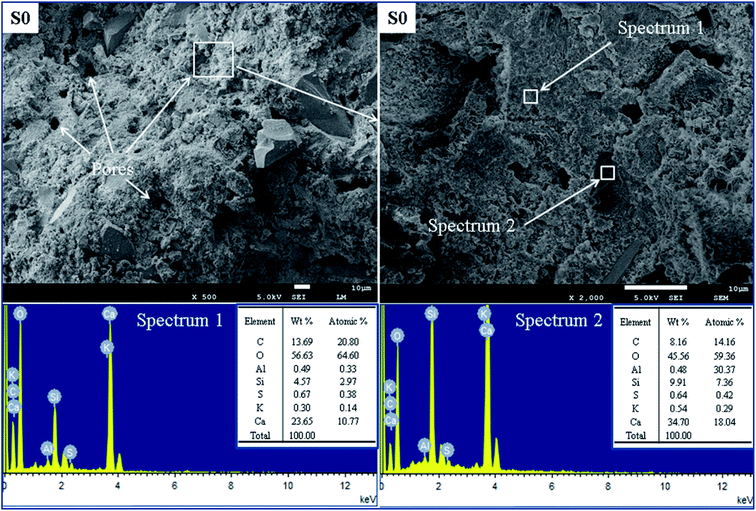
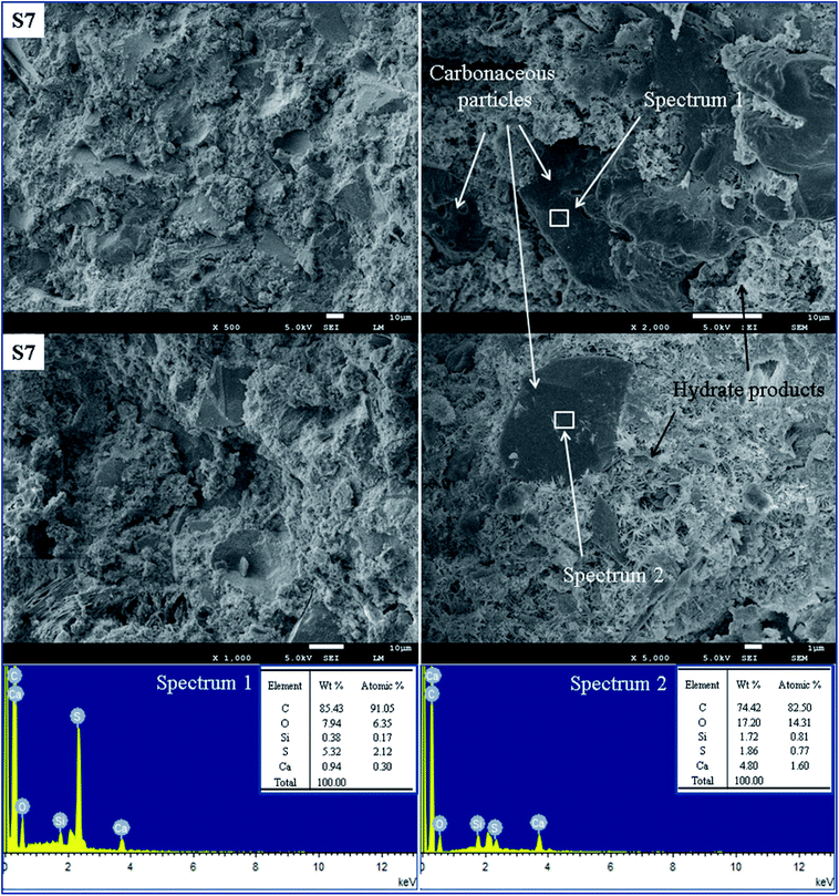
The microscopic structures and EDS analyses were carried out to reveal the mechanisms that influence the oil well cement pastes with carbonaceous materials. Fig. 14 presents the SEM images and EDS spectra of the control group S0 after hydration at 75 °C for 7 days. EDS analysis of the sample S0 can explain the elementary composition of the hydrate products. Fig. 15 shows the SEM images and EDS spectra of the cement specimen S7 hydrated under the same condition. The EDS analysis can verify the presence of carbonaceous materials in the cement pastes according to the elementary composition of the carbonaceous particles.
 |
| | Fig. 14 SEM images and EDS spectra of the control group S0. | |
 |
| | Fig. 15 SEM images and EDS spectra of the cement specimen S7. | |
Fig. 14 shows a mixture of hydrate products having a flocculent and porous structure of the C–S–H gel. In this paste, some large pores exist due to the crystallization of the formed hydrate products, and the presence of these pores results in a porous and loose structure of the cement. According to the elementary analysis shown in the spectrum 1 and spectrum 2 in Fig. 14 for S0, the high content of Ca, O, and Si element indicates that this area consists of hydrate products, which is used as a control group to identify the distribution of the carbonaceous materials. As seen in Fig. 15, the cement specimen containing carbonaceous materials has a denser and more compact structure with fewer pores as compared to the control group. EDS analysis of the sample S7 can help us identify the carbonaceous particles in the cement paste, and the high content of C and S elements can be observed because of petroleum coke and gilsonite. Fig. 15 shows the elemental composition of different microstructures in the matrix of sample S7. Noticeably seen in spectrum 1 and spectrum 2, the high ratio of C and S elements and the SEM images can be qualitative indicators illustrating that this area is mainly composed of carbonaceous materials. It can also be observed that the small carbonaceous particles with a particle size of less than 10 μm are embedded through the regions of the C–S–H gel in the cement slurry and are filled in the wide pores, whereas the larger particles (particle size more than 10 μm) are adhered with different kinds of hydrate products. That is one reason why these specimens form a more compact structure. However, the carbonaceous particles distributed in the cement paste could be adverse for bridging the cement particles and reduced the framework stress of the hardened cement, resulting in lower compressive strength as compared to that of the control group.
It is generally known that the material with a denser structure has a higher CTE.19 In addition, high content of the volatile matter in the carbonaceous materials plays a dominant role in the thermal expansion of the hardened cement paste. The volatile matter in the cement system expands and compensates for the shrinkage of the hydrate products because of dehydration when the temperature increases. Furthermore, the softening point of gilsonite is at about 130 °C. Thus, the gilsonite particles expand and their morphologies are transformed from solid to liquid, which can help these particles fill in the smaller pores when the temperature increases up to 130 °C. The expansion pressure caused by the expansion of the volatile matter and the transformation of the gilsonite particles leads to the swelling of set cement and restricts its shrinkage behavior. Therefore, the addition of carbonaceous admixtures can increase the CTE of the hardened cement paste.
4. Conclusions
In this study, the thermal expansion behavior of the set cement under anhydrous conditions was discussed, and the thermal-expansion admixtures used for cementing engineering in a thermal production well were optimized as carbonaceous materials could improve the thermal expansion property of the oil well cement. Although this improvement is limited, it can provide some guidance in designing new cement systems later. Based on the experimental results and the abovementioned discussions, the conclusions can be derived as follows.
(1) Replacing the oil well cement with carbonaceous admixtures (petroleum coke and gilsonite) increases the thermal expansion coefficients of the hardened cement pastes after curing at 75 °C and 200 °C, and the increase is directly related to the replacement ratio of the carbonaceous admixtures in the cement slurries.
(2) From the MIP data, it is clear that the addition of carbonaceous admixtures produces different variations in the pore structure of the cement specimens at the age of 7 days. The appropriate replacement ratio can improve the microstructure of the specimen via increasing the number of small pores and decreasing large pores as a result of the filling effect, which contributes to the increase in CTE.
(3) The thermal pressurization caused by the expansion of volatile matter and the phase transformation of carbonaceous particles in the paste when the temperature rapidly increases also results in the increase in the CTE of the set cement.
(4) After the cement is subjected to a high temperature history, the formation of hydrate products with good thermal stability because of the pozzolanic reaction of SiO2 narrows the CTE range of the hardened cement paste.
(5) The addition of carbonaceous admixtures has a negative influence on the compressive strength performance of the set cement; however, it still satisfies the needs of cementing engineering and guarantees the cementing quality.
Acknowledgements
This study was sponsored by the National Basic Research Program of China (2015CB251202), the Graduate Innovation Foundation of China University of Petroleum (YCX2017017), and the Program for Changjiang Scholars and Innovative Research Team in University (IRT1086).
References
- T. Lu, Z. Li and S. Li, et al., Enhanced heavy oil recovery after solution gas drive by water flooding, J. Pet. Sci. Eng., 2016, 137, 113–124 CrossRef CAS.
- A. Chougnet-Sirapian, E. Pershikova and A. Loiseau, New Steam Resilient Cement: Evaluation of Long-term Properties under Extreme Conditions, Paper SPE 141202 presented at the SPE International Symposium on Oilfield Chemistry, The Woodlands, Texas, USA, 2011, pp. 11–13 Search PubMed.
- A. Garnier, J. Saint-Marc and A. P. Bois, et al., A singular methodology to design cement sheath integrity exposed to steam stimulation, International Thermal Operations and Heavy Oil Symposium, Society of Petroleum Engineers, 2008 Search PubMed.
- G. G. Debruijn, C. Siso and D. Reinheimer, et al., Flexible cement improves wellbore integrity for steam assisted gravity drainage (SAGD) wells, International Thermal Operations and Heavy Oil Symposium. Society of Petroleum Engineers, 2008 Search PubMed.
- A. Loiseau, Thermal Expansion of Cement and Well Integrity of Heavy Oil Wells, SPE Heavy and Extra Heavy Oil Conference: Latin America, Society of Petroleum Engineers, 2014 Search PubMed.
- M. Nasir, O. S. B. Al-Amoudi and H. J. Al-Gahtani, et al., Effect of casting temperature on strength and density of plain and blended cement concretes prepared and cured under hot weather conditions, Constr. Build. Mater., 2016, 112, 529–537 CrossRef CAS.
- E. Grabowski and J. E. Gillott, Effect of replacement of silica flour with silica fume on engineering properties of oilwell cements at normal and elevated temperatures and pressures, Cem. Concr. Res., 1989, 19(3), 333–344 CrossRef CAS.
- R. B. Pernites and A. K. Santra, Portland cement solutions for ultra-high temperature wellbore applications, Cem. Concr. Compos., 2016, 72, 89–103 CrossRef CAS.
- M. Wyrzykowski and P. Lura, Controlling the coefficient of thermal expansion of cementitious materials – A new application for superabsorbent polymers, Cem. Concr. Compos., 2013, 35(1), 49–58 CrossRef CAS.
- E. M. Schulson, I. P. Swainson and T. M. Holden, Internal stress within hardened cement paste induced through thermal mismatch: Calcium hydroxide versus calcium silicate hydrate, Cem. Concr. Res., 2001, 31(12), 1785–1791 CrossRef CAS.
- Y. F. Fu, Y. L. Wong and C. A. Tang, et al., Thermal induced stress and associated cracking in cement-based composite at elevated temperatures – Part I: Thermal cracking around single inclusion, Cem. Concr. Compos., 2004, 26(2), 99–111 CrossRef CAS.
- A. Garnier, J. Saint-Marc and A. P. Bois, et al., An Innovative Methodology for Designing Cement-Sheath Integrity Exposed to Steam Stimulation, SPE Drill. Completion, 2010, 25(01), 58–69 CrossRef.
- G. K. White, Solids: thermal expansion and contraction, Contemp. Phys., 1993, 34(4), 193–204 CrossRef CAS.
- E. J. Sellevold and Ø. Bjøntegaard, Coefficient of thermal expansion of cement paste and concrete: mechanisms of moisture interaction, Mater. Struct., 2006, 39(9), 809–815 CrossRef CAS.
- Z. C. Grasley and D. A. Lange, Thermal dilation and internal relative humidity of hardened cement paste, Mater. Struct., 2007, 40(3), 311–317 CrossRef.
- Q. Zeng, K. Li and T. Fen-Chong, et al., Effect of porosity on thermal expansion coefficient of cement pastes and mortars, Constr. Build. Mater., 2012, 28(1), 468–475 CrossRef.
- S. Ghabezloo, Effect of porosity on the thermal expansion coefficient: A discussion of the paper ‘Effects of mineral admixtures on the thermal expansion properties of hardened cement paste’ by Z. H. Shui, R. Zhang, W. Chen, D. Xuan, Constr. Build. Mater. 24(9)(2010) 1761–1767, Constr. Build. Mater., 2010, 24(9), 1796–1798 CrossRef.
- I. Maruyama and A. Teramoto, Impact of time-dependant thermal expansion coefficient on the early-age volume changes in cement pastes, Cem. Concr. Res., 2011, 41(4), 380–391 CrossRef CAS.
- G. D. Alungbe, M. Tia and D. G. Bloomquist, Effect of aggregate, water-cement ratio, and curing on the coefficient of linear thermal expansion of concrete, Transp. Res. Rec., 1992, 1335, 44–51 Search PubMed.
- Z. Shui, R. Zhang and W. Chen, et al., Effects of mineral admixtures on the thermal expansion properties of hardened cement paste, Constr. Build. Mater., 2010, 24(9), 1761–1767 CrossRef.
- I. Maruyama and A. Teramoto, Effect
of water-retaining lightweight aggregate on the reduction of thermal expansion coefficient in mortar subject to temperature histories, Cem. Concr. Compos., 2012, 34(10), 1124–1129 CrossRef CAS.
- U. Kääntee, R. Zevenhoven and R. Backman, et al., Cement manufacturing using alternative fuels and the advantages of process modelling, Fuel Process. Technol., 2004, 85(4), 293–301 CrossRef.
- J. C. Hower, J. D. Robertson and J. M. Roberts, Petrology and minor element chemistry of combustion by-products from the co-combustion of coal, tire-derived fuel, and petroleum coke at a western Kentucky cyclone-fired unit, Fuel Process. Technol., 2001, 74(2), 125–142 CrossRef CAS.
- P. L. Zaleski, D. J. Derwin and W. H. Flood Jr, Electrically Conductive Paving Mixture and Pavement System, US Pat., 5707171, 1998-1-13.
- P. Xie and J. J. Beaudo, Electrically conductive concrete and its application in deicing, in Proceedings of the 2nd CANM ET/ACI International Symposium on Advances in Concrete Technology, SP2154, American Concrete Institute, Farmington Hills, Mich, USA, 1995, pp. 399–417 Search PubMed.
- J. Cao and D. Chung, Coke powder as an admixture in cement for electromagnetic interference shielding, Carbon, 2003, 41(12), 2433–2436 CrossRef CAS.
- R. A. Khushnood, S. Ahmad and P. Savi, et al., Improvement in electromagnetic interference shielding effectiveness of cement composites using carbonaceous nano/micro inerts, Constr. Build. Mater., 2015, 85, 208–216 CrossRef.
- M. Frías, J. M. Jiménez-Mateos, J. Pfretzschner, J. Olmeda, R. M. Rodríguez and M. I. Sánchezde Rojas, Development of blended cement mortars with acoustic properties using petroleum coke, Constr. Build. Mater., 2011, 25, 1086–1092 CrossRef.
- Well cementing compositions, US Pat., 3,220,863, 1965-11-30.
- K. A. Slagle and L. G. Carter, Gilsonite-A Unique Additive for Oil-well Cements, Drilling and Production Practice, American Petroleum Institute, 1959 Search PubMed.
- E. Broni-Bediako, O. F. Joel and G. Ofori-Sarpong, Oil Well Cement Additives: A Review of the Common Types, Oil & Gas Research, 2016, 2, 112 Search PubMed.
- S. Le Roy-Delage and L. Martin, Self-adaptive cements, US Pat., 9,222,011, 2015-12-29.
- F. Mitchell, Low density cement composition, US Pat., 3,376,146, 1968-4-2.
- J. Olmeda, M. I. S. De Rojas and M. Frías, et al., Effect of petroleum (pet) coke addition on the density and thermal conductivity of cement pastes and mortars, Fuel, 2013, 107, 138–146 CrossRef CAS.
- G. Debruijn, R. Williams and E. Therond, Carbonaceous extenders for flexible cement, US Pat., 7,836,953, 2010-11-23.
- A. Loiseau, A. Chougnet-Sirapian and E. Tomilina, et al., Compositions and Methods for Well Completions, US Pat., Application 13/814,724, 2010-8–18.
- American Petroleum Institute, Recommended practice for testing well cements, 2nd edn, April 2013 Search PubMed.
- E. Karakosta, L. Lagkaditi and S. ElHardalo, et al., Pore structure evolution and strength development of G-type elastic oil well cement. A combined 1H NMR and ultrasonic study, Cem. Concr. Res., 2015, 72, 90–97 CrossRef CAS.
- Y. Bu, J. Du and S. Guo, et al., Properties of oil well cement with high dosage of metakaolin, Constr. Build. Mater., 2016, 112, 39–48 CrossRef CAS.
- J. J. Valenza and G. W. Scherer, Evidence of anomalous thermal expansion of water in cement paste, Cem. Concr. Res., 2005, 35(1), 57–66 CrossRef CAS.
- H. Liu, Y. Bu and A. Nazari, et al., Low elastic modulus and expansive well cement system: The application of gypsum microsphere, Constr. Build. Mater., 2016, 106, 27–34 CrossRef CAS.
- American Petroleum Institute, Specification for Cements and Materials for Well Cementing, 24th edn, December 2010 Search PubMed.
|
| This journal is © The Royal Society of Chemistry 2017 |

 Open Access Article
 This Open Access Article is licensed under a
  *a,
Jiapei Dua and
Dongming Liub
*a,
Jiapei Dua and
Dongming Liub