 Open Access Article
Creative Commons Attribution 3.0 Unported Licence
Fabrication of TiO2 coated porous CoMn2O4 submicrospheres for advanced lithium-ion anodes
Jun Zhoua,
Shuang Cheng *a,
Yu Jianga,
Fenghua Zhenga,
Xing Oua,
Lufeng Yanga,
Mengkun Wanga,
Minghai Yaoa and
Meilin Liu
 *ab
*ab
aGuang Zhou Key Laboratory of Energy Materials Surface Chemistry, New Energy Research Institute, School of Environment and Energy, South China University of Technology, Guangzhou, 510006, China. E-mail: escheng@scut.edu.cn; Tel: +86-020-39380525
bSchool of Materials Science and Engineering, Georgia Institute of Technology, Atlanta, GA 30332-0245, USA. E-mail: meilin.liu@mse.gatech.edu; Tel: +1-404-894-6114
First published on 13th April 2017
Abstract
Herein, a facile and general way for the synthesis of TiO2 coated cobalt manganese oxide CoMn2O4 (CMO) has been developed. In this contribution, uniform Co0.33Mn0.67CO3 spheres are firstly fabricated via a solvothermal method. Porous CMO with a diameter of about 800 nm is obtained by a subsequent annealing procedure. Finally, a thin layer of TiO2 is coated on the surface of the CMO through a hydrolysis and subsequent condensation process. When evaluated as anode materials for lithium ion batteries (LIBs), after 500 cycles at a current density of 1000 mA g−1, the CMO@TiO2 spheres possessed high reversible capacities of 940 mA h g−1 with a suitable discharge plateau of ∼0.6 V, much higher than the pristine CMO. In addition, the CMO@TiO2 shows better rate performance than CMO, as high as 196 mA h g−1 at a very fast discharge current of 5 A g−1. The high electrochemical performance of CMO@TiO2 should be attributed to its special structure of nanometer scale spheres with high porosity and the thin layer coating of TiO2 as a zero-strain shell, which can effectively reduce the diffusion length of electrolyte, Li+ and electrons, buffer volume expansion during the Li+ insertion/extraction processes and thus reduce the materials' pulverization.
1. Introduction
Lithium ion batteries (LIBs) have become one of the most important power sources for portable devices, electric vehicles and energy storage power stations nowadays, but the development of advanced batteries with higher energy density and power density within a certain weight or volume is still a challenge. As an indispensable part of LIBs, anode materials play a key role in improving the performance of batteries and have always been a focus of the energy storage area. Up to now, carbon materials and Li4Ti5O12 are the two commonly used commercial anode materials, and Si-based anode materials are regarded as most commercial potential materials for next generation LIBs.1–3 Transition metal oxides (TMOs), such as Co3O4,4–6 Mn3O4,7,8 Fe2O3,9,10 and NiO11 also have long been reckoned as potential anode materials for LIBs due to their many attractive features, including high theoretical capacities, high power density and environmental benign. However, these materials inevitably suffer from several major problems: severe volume changes during charge–discharge processes, agglomeration and pulverization of particles, and poor electronic conductivity.12 New research is constantly being carried out to meet the increasing requirements for LIBs anodes. In recent years, mixed transition metal oxides (MTMOs) have been attracting great research interest as anodes in LIBs owing to their outstanding features:13 (1) synergistic effect, attributed to different expansion coefficients of two types of metal elements; (2) higher reversible capacities, due to its complex chemical compositions which can alloy with more Li ions compared with normal metal oxides;14 (3) higher electrical conductivity, owing to relatively low activation energy; (4) more environmental benign. A promising family of MTMOs is AxB3−xO4 (A, B = Co, Ni, Zn, Mn, Fe, etc.), typically in a spinel structure. Sun et al.13 and Lou et al.15 reviewed the most common MTMOs in their literature, such as NiCo2O4,16 ZnCo2O4,17 ZnMn2O4,18 CoMn2O4,19 CoFe2O4,20 ZnFe2O4.21CoMn2O4, with a high Mn proportion, is becoming one of the most potential anode and has attracted the attention of researchers due to its not only high capacity but also suitable discharge plateau (∼0.6 V) as well as low cost.22 Just like TMOs, MTMOs also share the disadvantage of large volume changes, agglomeration, pulverization and poor electronic conductivity to some extent. Nanostructuring and coating to form hybrid materials are two common approaches to address these challenges.1,23 In the case of CoMn2O4 (CMO), numerous nanostructure, such as nanowires,24 nanofibers,25 nanorods,26 porous sphere,27 hollow spheres28 as well as its composite with graphene29,30 have been studied by many researchers and good electrochemical performance has been achieved. Coating to form a buffering matrix is always another effective method to relieve the rapid fading capacity during charge–discharge processes. TiO2 is considered a suitable zero-strain shell for application in LIBs anodes. Its fascinating features, such as plentiful polymorphs, good chemical and thermal stability, excellent electronic and optical properties render it greatly promising not only in photocatalysis, solar cells but also in LIBs.31 Various TiO2 with different structure and morphology have been synthesized and investigated as anodes in LIBs. For example, porous TiO2 spheres composed of interconnected nanorods32 and porous TiO2 urchins constructed from connected nanocrystals33 have ever been studied and hierarchical structured TiO2 showed better performance than commercial TiO2. In addition, great effort has been directed toward synthesis of core@TiO2 structures. For example, Wang et al.34 fabricated SnO2@TiO2 core–shell structure as anode materials for LIBs, which displayed excellent electrochemical performance. Zhao et al.35 successfully constructed core–shell α-Fe2O3@TiO2 microellipsoids and studied the formation mechanisms in detail. Kim et al.36 synthesized SiO2@TiO2 spherical core–shell particles and they presented good catalytic performance in decomposing methyl orange. So far, no literature has reported TiO2 coated CMO as anode materials for LIBs.
In this work, a simple solvothermal approach was designed for the synthesis of carbonate precursors of CMO. After the carbonate precursors were calcined in air at 600 °C for 3 h, uniform porous CMO spheres with high yields were obtained. Surprisingly, the porous CMO spheres with diameters of 600–800 nm consist of numerous polyhedral nanoparticles. The obtained CMO was further used as the original material to synthesize the CMO@TiO2 core–shell structure through a hydrolysis and condensation process using tetrabutyl titanate (TBOT) as the titanium source and the ammonia as the catalyst. The as-obtained porous CMO@TiO2 spheres exhibit good cycling and rate performance when utilized as anode materials. The first discharge capacities of CMO and CMO@TiO2 are 959 and 1100 mA h g−1, respectively, showing an initial efficiencies of 70.4% and 67.6%, respectively. After cycling at a current density of 1000 mA g−1 for 500 cycles, the specific capacity of CMO@TiO2 was stabilized at around 940 mA h g−1, much higher than pristine CMO.
2. Experimental procedure
2.1. Sample synthesis
All the reagents used were supplied by Damao Chemical Reagent Factory (Tianjin, China) of analytical grade and used without any further purification.2.2. Characterizations
X-ray diffraction (XRD) patterns were recorded on a Bruker D8 advance X-ray diffractometer using Cu Kα radiation (λ = 0.15406 nm). X-ray photoelectron spectroscopy (XPS) measurements were performed on a PHI Quantera II instrument with Al Kα radiation. Scanning electron microscopy (SEM) images were obtained using a field emission scanning electron microscope (FE-SEM, Hitachi LEO 1530). Transmission electron microscopy (TEM) and high-resolution TEM (HRTEM) were taken on a JEM-2100F.2.3. Electrochemical measurements
Electrochemical measurements were performed at 25 °C in thermostat using CR 2025-type coin cells with Celgard 2400 porous polypropylene membrane as separator, lithium-foil as both counter electrode and reference electrode and 1 M LiPF6 in EC/DMC (1![[thin space (1/6-em)]](https://www.rsc.org/images/entities/char_2009.gif) :
:![[thin space (1/6-em)]](https://www.rsc.org/images/entities/char_2009.gif) 1 by volume) as electrolyte. The working electrode was prepared by making a slurry of active materials, acetylene black (AB), and polyvinylidene difluoride (PVDF) in a weight ratio of powder/AB/PVDF = 7
1 by volume) as electrolyte. The working electrode was prepared by making a slurry of active materials, acetylene black (AB), and polyvinylidene difluoride (PVDF) in a weight ratio of powder/AB/PVDF = 7![[thin space (1/6-em)]](https://www.rsc.org/images/entities/char_2009.gif) :
:![[thin space (1/6-em)]](https://www.rsc.org/images/entities/char_2009.gif) 2
2![[thin space (1/6-em)]](https://www.rsc.org/images/entities/char_2009.gif) :
:![[thin space (1/6-em)]](https://www.rsc.org/images/entities/char_2009.gif) 1 in N-methylpyrrolidone (NMP) onto a copper foil current collector and then drying at 80 °C under vacuum for 10 h, and a mass loading of the active materials was about 0.45–0.5 mg cm−1. The cells were assembled in an Ar-filled glovebox with moisture and oxygen contents both below 0.1 ppm. The cycling and rate performance tests of the samples were performed on a Land battery test system (CT2001A). The cyclic voltammetry (CV) was tested in the voltage of 0.01 to 3.0 V at a scan rate of 0.1 mV s−1 by an electrochemical workstation (CHI660E).
1 in N-methylpyrrolidone (NMP) onto a copper foil current collector and then drying at 80 °C under vacuum for 10 h, and a mass loading of the active materials was about 0.45–0.5 mg cm−1. The cells were assembled in an Ar-filled glovebox with moisture and oxygen contents both below 0.1 ppm. The cycling and rate performance tests of the samples were performed on a Land battery test system (CT2001A). The cyclic voltammetry (CV) was tested in the voltage of 0.01 to 3.0 V at a scan rate of 0.1 mV s−1 by an electrochemical workstation (CHI660E).
3. Results and discussion
3.1. Structure and morphology characterization
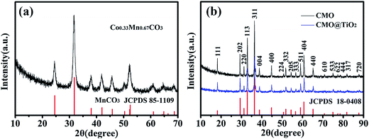
The synthesis process of porous CMO@TiO2 submicrospheres is depicted in Fig. 1. Pink carbonate precursor is first synthesized through a solvothermal process with assistant of NH4HCO3. The precursor is then calcinated under air to form porous CMO submicrospheres which can be ascribed to the escape of CO2 gas from the material during the heating process. Subsequently, a thin layer of TiO2 was coated on the surface of the spheres through a hydrolysis and following condensation process using TBOT as titanium source and ammonia as catalyst and a composite of CMO@TiO2 with sphere morphology was finally obtained.The chemical compositions of the samples were first characterized by X-ray diffraction (XRD) technology and presented in Fig. 2. Fig. 2a shows the XRD pattern of the carbonate precursor prepared through NH4HCO3 assisted solvothermal process with the molar ratio of Co and Mn being 1![[thin space (1/6-em)]](https://www.rsc.org/images/entities/char_2009.gif) :
:![[thin space (1/6-em)]](https://www.rsc.org/images/entities/char_2009.gif) 2. By comparison with MnCO3 (JCPDS no. 85-1109), all the diffraction peaks could be indexed on the basis of the hexagonal phase with a space group R
2. By comparison with MnCO3 (JCPDS no. 85-1109), all the diffraction peaks could be indexed on the basis of the hexagonal phase with a space group R![[3 with combining macron]](https://www.rsc.org/images/entities/char_0033_0304.gif) c (no. 167).28 After calcined at 600 °C for 3 hours in air, all of the reflections could be indexed as tetragonal (Co, Mn)(Co, Mn)2O4 (a = b = 8.09 Å, c = 9.27 Å; Co
c (no. 167).28 After calcined at 600 °C for 3 hours in air, all of the reflections could be indexed as tetragonal (Co, Mn)(Co, Mn)2O4 (a = b = 8.09 Å, c = 9.27 Å; Co![[thin space (1/6-em)]](https://www.rsc.org/images/entities/char_2009.gif) :
:![[thin space (1/6-em)]](https://www.rsc.org/images/entities/char_2009.gif) Mn = 1
Mn = 1![[thin space (1/6-em)]](https://www.rsc.org/images/entities/char_2009.gif) :
:![[thin space (1/6-em)]](https://www.rsc.org/images/entities/char_2009.gif) 2; JCPDS no. 18-0408) with a spinel structure, as illustrated in Fig. 2b. No other diffraction peaks are observed, implying a high purity of the products. For the CMO@TiO2 composite, the diffraction peaks agree well with the CMO except that the intensities of the peaks decrease. No clear TiO2 diffraction peaks can be seen from the pattern, which may ascribe to its low content.
2; JCPDS no. 18-0408) with a spinel structure, as illustrated in Fig. 2b. No other diffraction peaks are observed, implying a high purity of the products. For the CMO@TiO2 composite, the diffraction peaks agree well with the CMO except that the intensities of the peaks decrease. No clear TiO2 diffraction peaks can be seen from the pattern, which may ascribe to its low content.
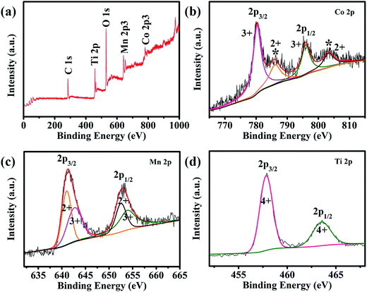
XPS analyses were carried out to further investigate the composition of CMO@TiO2 and the valence states of its metal ions. All of the binding energies in this XPS analysis were corrected for specimen charging by referencing them to the C 1s peak (set at 284.6 eV). As shown in the survey scan of CMO@TiO2 (Fig. 3a), the CMO@TiO2 hybrid contains four elements (except carbon): cobalt, manganese, oxygen and titanium. In the Co 2p spectrum of Fig. 3b, peak at 781.2 eV is assigned to Co 2p3/2, while the peak at 796.9 eV is attributed to Co 2p1/2. Whereas, the two peaks are accompanied by two prominent shakeup satellite peaks (786.3 and 802.9 eV, respectively). The main peaks and satellite peaks indicate the presence of Co(II) and Co(III) cations.29,37–39 It can be seen from Fig. 3c that the Mn 2p spectrum exhibits two peaks at 641.7 and 653.3 eV which can be referred to the binding energies of the 2p3/2 and 2p1/2, respectively. After refined fitting, the spectrum can be divided into four peaks. Among them, 641.5 and 653.0 eV can be assigned to the existence of Mn(II), while other two peaks at 642.9 and 653.7 eV are characteristic of Mn(III) cation.40 In Fig. 3d, XPS investigation on the titanium chemical state shows two binding energy located at 458.5 eV and 464.1 eV, which can be indexed to Ti 2p3/2 and Ti 2p1/2, respectively, indicating a valance state of Ti(IV).41,42
The morphology and microstructure of the carbonate precursors and corresponding CMO@TiO2 were then characterized by scanning electron microscopy (SEM). As shown in Fig. 4a, the precursor is formed with well-defined spheres with an average diameter of about 800 nm. While, the spheres are composed of countless much smaller polyhedral nanoparticles and hence cause the formation of a rough surface (Fig. 4b). After calcinated in air, the carbonate particles are transformed into CMO spheres with a similar diameter but much porous structure due to the release of CO2 during calcination. After coating with TiO2, the morphology is remained (Fig. 4c). From the enlarged SEM image of Fig. 4d, it can be seen that the nanoparticles that make up the spheres become larger after calcination, compared with those of the carbonate precursor, and a lot voids are formed. Besides, elemental mapping image of the porous spheres (Fig. 4e) show well matched spatial distributions of Co, Mn, O and Ti, further confirming the successful coating of TiO2, which is agreed well with the XPS analysis.
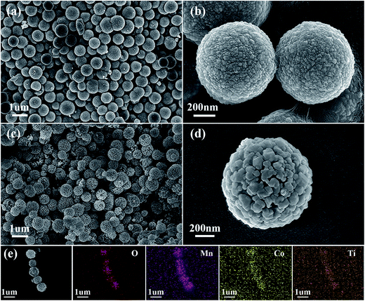 | ||
| Fig. 4 SEM images of the (a and b) Co–Mn carbonate precursors, (c and d) the CMO@TiO2 composite and (e) a strand of submicrospheres and the corresponding EDX elemental mappings of O, Mn, Co and Ti. | ||
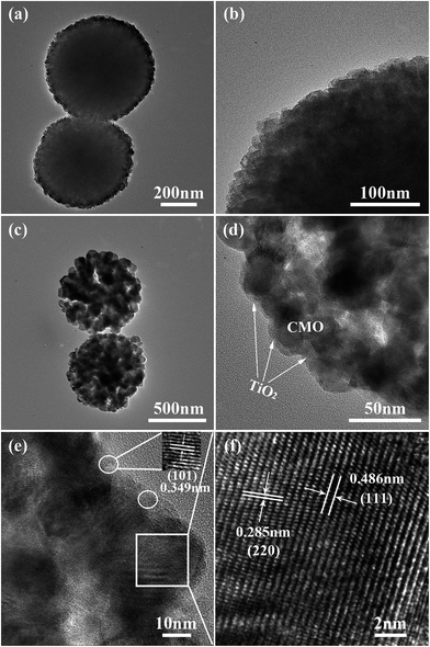
To get more detailed information about the morphology and the crystal structure of the materials, TEM and HRTEM observations were employed. It can be found from Fig. 5a that the carbonate precursors have a solid interior structure and its rough surface can be clearly seen from a higher magnification image in Fig. 5b, which is in consistent with the SEM results. CMO porous spheres are obtained by sintering the carbonate precursors at 600 °C for 3 h in air. After coating with TiO2, the porous structure is remained (Fig. 5c) and a thin layer can be seen along the edge of CMO, as indicated by the arrows in Fig. 5d. In one white oval area of the HRTEM image (Fig. 5e), distinct lattice fringes with an interplanar spacing of 0.349 nm (enlarged in the inset at the right top) can be observed, which can be attributed to the (101) plane of TiO2 phase, verifying the thin coating layer is indeed TiO2.
Besides, another HRTEM region standing for the core substance is marked with white square (Fig. 5e). From its enlarged image in Fig. 5f, clear lattice fringes with an interplanar distance of 0.486 nm and 0.285 nm can be observed, corresponding to the spacings of (111) and (220) planes of CMO crystals, respectively, which is agreed well with the XRD analysis.
3.2. Electrochemical properties
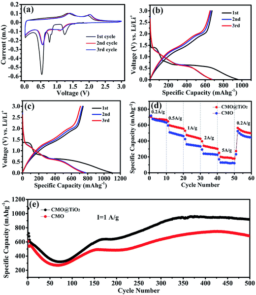
After assembled to be half-cells, electrochemical properties of the CMO@TiO2 and CMO are characterized and presented in Fig. 6. Fig. 6a shows the cyclic voltammetry (CV) curves of CMO@TiO2 electrodes at a scan rate of 0.1 mV s−1 in a potential range 0.01–3.0 V. As can be seen, the CV curve for the first cycle is obviously different from those of the subsequent ones. In the first reduction sweep, three peaks at ∼1.24 V, ∼0.53 V and ∼0.77 V can be found. The broad peak at ∼1.24 V can be assigned to the reduction of Co3+ and Mn3+ to Co2+ and Mn2+, and the sharp peak at ∼0.53 V is attributed to the reduction of Co2+ and Mn2+ to metallic Co and Mn, respectively,25,43,44 while the minor peak at ∼0.77 V can be ascribed to the irreversible decomposition of the solvent in the electrolyte to form the solid electrolyte interface (SEI).19,45 Two broad oxidation peaks are observed at ∼1.34 and 1.97 V in the anodic scan, corresponding to the oxidation of Mn to Mn2+ and Co to Co2+, respectively. From the second cycle onward, the repeated redox peaks at 0.55/1.42 V and 1.14/2.03 V belong to the reduction-oxidation of MnO/Mn and CoO/Co, respectively.28 Furthermore, voltage gaps of the redox couples are increased at the second cycle, implying irreversible reactions and capacity fading, which should be attributed to polarization and possible agglomeration of the materials.46 On the basis of the CV analysis above, the entire electrochemical process can be indicated as follows:| CoMn2O4 + 8Li+ + 8e− → Co + 2Mn + 4Li2O | (1) |
| Co + 2Mn + 3Li2O ⇌ CoO + 2MnO + 6Li+ + 6e− | (2) |
The discharge–charge profiles of the CMO and CMO@TiO2 porous spheres at a current density of 200 mA g−1 for the 1st, 2nd, 3rd cycles are exhibited in Fig. 6b and c, respectively. The CMO electrode delivers initial discharge and charge capacities of 958.9 and 675.1 mA h g−1, respectively, corresponding to a coulombic efficiency of 70.4%, while CMO@TiO2 electrode gives initial discharge and charge capacities of 1100.8 and 743.8 mA h g−1 with a slight lower coulombic efficiency of 67.5%. The formation of the SEI film and partial decomposition of Li2O are likely responsible for the large irreversible capacity loss during the first cycle. Other factors, such as kinetic limitations and the intrinsic nature of the materials, may also play a part. From the second cycle onward, the coulombic efficiency increases to about 98% and retains this value for the subsequent cycles.
Rate performance of the samples were then studied at different current densities stepwise from 200 to 5000 mA g−1 with ten cycles for each step after initially activate for 2 cycles at a current density of 100 mA g−1 (Fig. 6d). As seen from the figure, CMO@TiO2 shows better rate capability than that of CMO with average discharge capacities of 676, 582, 459, 328 and 196 mA h g−1 at 200, 500, 1000, 2000 and 5000 mA g−1, respectively. The improved rate performance may be aroused from the nano-scaled self-building electric field and some defects at the continuous coherent heterointerfaces of the CMO and the TiO2 coating layer.47–49
To further investigate the electrochemical performance of the samples before and after coating, long cycling test at a current density of 1000 mA g−1 for 500 cycles was performed and the corresponding results are exhibited in Fig. 6e. Capacities of the two samples show a similar trend that goes down in the first 75 cycles and then gradually increases to a certain value. For sample CMO@TiO2, it still suffer from severe structure degradation because of the volume change resulting from conversion reaction. SEI films will fracture and new active surfaces will be exposed accompanied by the growth of new SEI along with the morphology change. This can bring enormous capacity fading, especially at higher current density.46,50 The subsequent capacity increase should be attributed to the high-rate lithiation induced reactivation due to the construction of new structures and optimized stable SEI.51–53
It is apparent that the CMO@TiO2 electrode exhibits much improved rate and cycling capabilities, which can be ascribed to the following reasons: (1) the thin layer of TiO2 as a zero-strain shell together with the porous structure can constrain the large volume change of the CMO materials to some extent and thus reduce the materials from pulverization, leading to improvement in capacity retention upon extended cycling; (2) self-building electric field and some defects, such as TiMn, were formed at the interface of TiO2 and CMO, which can probably enhance the conductivity of CMO and hence the rate capacity.
4. Conclusions
In summary, this work reports a facile method for a controllable preparation of porous CMO and CMO@TiO2 spheres. When evaluated as anode materials, the CMO@TiO2 exhibits better cycling and rate performance than the pristine CMO. The excellent electrochemical performance may originate from the nano-sized particles, porous structure and the thin layer coating of TiO2. As a coating layer, the zero-strain TiO2 shell may effectively buffer the large volume change and prevent the materials from pulverization during the charge/discharge processes. This work shows that metal oxides coating is an effective way to improve the performance of mixed transition metal oxides, which effectively promote their potential applications as anode materials for next generation energy storage electrodes.Acknowledgements
This work was supported by the National Science Foundation for Young Scientists of China (no. 21403073), Fundamental Research Funds for Central Universities of SCUT, China (no. 2015ZZ118) and Guangdong Innovative and Entrepreneurial Research Team Program (2014ZT05N200).References
- B. Zhao, R. Ran, M. L. Liu and Z. P. Shao, Mater. Sci. Eng., R, 2015, 98, 1–71 CrossRef.
- X. Han, H. X. Chen, Z. Q. Zhang, D. L. Huang, J. F. Xu, C. Li, S. Y. Chen and Y. Yang, J. Mater. Chem. A, 2016, 4, 17757–17763 CAS.
- H. Wu, G. Chan, J. W. Choi, I. Ryu, Y. Yao, M. T. McDowell, S. W. Lee, A. Jackson, Y. Yang, L. B. Hu and Y. Cui, Nat. Nanotechnol., 2012, 7, 310–315 CrossRef CAS PubMed.
- J. Y. Wang, N. L. Yang, H. J. Tang, Z. H. Dong, Q. Jin, M. Yang, D. Kisailus, H. J. Zhao, Z. Y. Tang and D. Wang, Angew. Chem., Int. Ed., 2013, 52, 6417–6420 CrossRef CAS PubMed.
- H. Wu, M. Xu, Y. C. Wang and G. F. Zheng, Nano Res., 2013, 6, 167–173 CrossRef CAS.
- Q. Guan, J. L. Cheng, B. Wang, W. Ni, G. F. Gu, X. D. Li, L. Huang, G. C. Yang and F. D. Nie, ACS Appl. Mater. Interfaces, 2014, 6, 7626–7632 CAS.
- S. Z. Huang, Y. Cai, J. Jin, J. Liu, Y. Li, Y. Yu, H. E. Wang, L. H. Chen and B. L. Su, Nano Energy, 2015, 12, 833–844 CrossRef CAS.
- S. Y. Gao and K. Geng, Nano Energy, 2014, 6, 44–50 CrossRef CAS.
- K. Z. Cao, L. F. Jiao, H. Q. Liu, Y. C. Liu, Y. J. Wang, Z. P. Guo and H. T. Yuan, Adv. Energy Mater., 2015, 5, 1401421 CrossRef.
- W. J. Yu, L. L. Zhang, P. X. Hou, F. Li, C. Liu and H. M. Cheng, Adv. Energy Mater., 2016, 6, 1501755 CrossRef.
- Z. Y. Fan, J. Liang, W. Yu, S. J. Ding, S. D. Cheng, G. Yang, Y. L. Wang, Y. X. Xi, K. Xi and R. V. Kumar, Nano Energy, 2015, 16, 152–162 CrossRef CAS.
- Y. Xiao, C. W. Hu and M. H. Cao, J. Power Sources, 2014, 247, 49–56 CrossRef CAS.
- Y. Zhao, X. F. Li, B. Yan, D. B. Xiong, D. J. Li, S. Lawes and X. L. Sun, Adv. Energy Mater., 2016, 6, 1502175 CrossRef.
- C. T. Cherian, J. Sundaramurthy, M. V. Reddy, P. S. Kumar, K. Mani, D. Pliszka, C. H. Sow, S. Ramakrishna and B. V. R. Chowdari, ACS Appl. Mater. Interfaces, 2013, 5, 9957–9963 CAS.
- C. Z. Yuan, H. B. Wu, Y. Xie and X. W. Lou, Angew. Chem., Int. Ed., 2014, 53, 1488–1504 CrossRef CAS PubMed.
- L. F. Shen, L. Yu, X. Y. Yu, X. G. Zhang and X. W. Lou, Angew. Chem., Int. Ed., 2015, 54, 1868–1872 CrossRef CAS PubMed.
- Q. B. Zhang, J. X. Wang, J. C. Dong, F. Ding, X. H. Li, B. Zhang, S. H. Yang and K. L. Zhang, Nano Energy, 2015, 13, 77–91 CrossRef CAS.
- N. N. Wang, X. J. Ma, H. Y. Xu, L. Chen, J. Yue, F. E. Niu, J. Yang and Y. T. Qian, Nano Energy, 2014, 6, 193–199 CrossRef CAS.
- L. Zhou, D. Y. Zhao and X. W. Lou, Adv. Mater., 2012, 24, 745–748 CrossRef CAS PubMed.
- Y. Wang, D. W. Su, A. Ung, J. H. Ahn and G. X. Wang, Nanotechnology, 2012, 23, 055402 CrossRef CAS PubMed.
- L. R. Hou, L. Lian, L. H. Zhang, G. Pang, C. Z. Yuan and X. G. Zhang, Adv. Funct. Mater., 2015, 25, 238–246 CrossRef CAS.
- L. H. Zhang, L. R. Hou, L. Lian, L. S. Wang and C. Z. Yuan, Rare Met. Mater. Eng., 2016, 45, 1910–1916 Search PubMed.
- P. G. Bruce, B. Scrosati and J. M. Tarascon, Angew. Chem., Int. Ed., 2008, 47, 2930–2946 CrossRef CAS PubMed.
- Y. N. Xu, X. F. Wang, C. H. An, Y. J. Wang, L. F. Jiao and H. T. Yuan, J. Mater. Chem. A, 2014, 2, 16480–16488 CAS.
- G. R. Yang, X. Xu, W. Yan, H. H. Yang and S. J. Ding, Electrochim. Acta, 2014, 137, 462–469 CrossRef CAS.
- L. J. Wang, B. Liu, S. H. Ran, L. M. Wang, L. N. Gao, F. Y. Qu, D. Chen and G. Z. Shen, J. Mater. Chem. A, 2013, 1, 2139–2143 CAS.
- L. Hu, H. Zhong, X. R. Zheng, Y. M. Huang, P. Zhang and Q. W. Chen, Sci. Rep., 2012, 2, 986 Search PubMed.
- J. F. Li, S. L. Xiong, X. W. Li and Y. T. Qian, Nanoscale, 2013, 5, 2045–2054 RSC.
- Y. S. Liu, J. Li, W. Z. Li, Y. M. Li, Q. Y. Chen and F. Q. Zhan, J. Power Sources, 2015, 299, 492–500 CrossRef CAS.
- G. X. Gao, S. Y. Lu, Y. Xiang, B. T. Dong, W. Yan and S. J. Ding, Dalton Trans., 2015, 44, 18737–18742 RSC.
- X. Chen and S. S. Mao, Chem. Rev., 2007, 107, 2891–2959 CrossRef CAS PubMed.
- Y. Cai, H. E. Wang, J. Jin, S. Z. Huang, Y. Yu, Y. Li, S. P. Feng and B. L. Su, Chem. Eng. J., 2015, 281, 844–851 CrossRef CAS.
- Y. Cai, H. E. Wang, S. Z. Huang, M. F. Yuen, H. H. Cai, C. Wang, Y. Yu, Y. Li, W. J. Zhang and B. L. Su, Electrochim. Acta, 2016, 210, 206–214 CrossRef CAS.
- Z. Yi, Q. G. Han, P. Zan, Y. Cheng, Y. M. Wu and L. M. Wang, J. Mater. Chem. A, 2016, 4, 12850–12857 CAS.
- W. Li, J. P. Yang, Z. X. Wu, J. X. Wang, B. Li, S. S. Feng, Y. H. Deng, F. Zhang and D. Y. Zhao, J. Am. Chem. Soc., 2012, 134, 11864–11867 CrossRef CAS PubMed.
- J. W. Lee, M. R. Othman, Y. Eom, T. G. Lee, W. S. Kim and J. Kim, Microporous Mesoporous Mater., 2008, 116, 561–568 CrossRef CAS.
- S. A. Needham, G. X. Wang, K. Konstantinov, Y. Tournayre, Z. Lao and H. K. Liu, Electrochem. Solid-State Lett., 2006, 9, A315–A319 CrossRef CAS.
- S. L. Xiong, J. S. Chen, X. W. Lou and H. C. Zeng, Adv. Funct. Mater., 2012, 22, 861–871 CrossRef CAS.
- L. Liu, H. J. Zhang, J. Yang, Y. P. Mu and Y. Wang, J. Mater. Chem. A, 2015, 3, 22393–22403 CAS.
- L. H. Zhang, S. Q. Zhu, H. Cao, L. R. Hou and C. Z. Yuan, Chem.–Eur. J., 2015, 21, 10771–10777 CrossRef CAS PubMed.
- M. Sathish, B. Viswanathan, R. P. Viswanath and C. S. Gopinath, Chem. Mater., 2005, 17, 6349–6353 CrossRef CAS.
- H. G. Yang and H. C. Zeng, J. Phys. Chem. B, 2004, 108, 3492–3495 CrossRef CAS.
- M. H. Kim, Y. J. Hong and Y. C. Kang, RSC Adv., 2013, 3, 13110–13114 RSC.
- Y. R. Liu, B. C. Zhang, J. K. Feng and S. L. Xiong, RSC Adv., 2015, 5, 26863–26871 RSC.
- L. X. Zhang, G. F. He, S. W. Lei, G. S. Qi, H. F. Jiu and J. Wang, J. Power Sources, 2016, 326, 505–513 CrossRef CAS.
- X. Zhao, J. H. Sui, F. Li, H. T. Fang, H. G. Wang, J. Y. Li, W. Cai and G. Z. Cao, Nanoscale, 2016, 8, 17902–17910 RSC.
- Y. Cai, H. E. Wang, X. Zhao, F. Huang, C. Wang, Z. Deng, Y. Li, G. Z. Cao and B. L. Su, ACS Appl. Mater. Interfaces, 2017, 9, 10652–10663 CAS.
- T. F. Zhou, Y. Zheng, H. Gao, S. D. Min, S. Li, H. K. Liu and Z. P. Guo, Adv. Sci., 2015, 2, 1500027 CrossRef PubMed.
- H. T. Fang, M. Liu, D. W. Wang, T. Sun, D. S. Guan, F. Li, J. Zhou, T. K. Sham and H. M. Cheng, Nanotechnology, 2009, 20, 225701 CrossRef PubMed.
- G. D. Li, L. Q. Xu, Y. J. Zhai and Y. P. Hou, J. Mater. Chem. A, 2015, 3, 14298–14306 CAS.
- Y. Z. Jiang, D. Zhang, Y. Li, T. Z. Yuan, N. Bahlawane, C. Liang, W. P. Sun, Y. H. Lu and M. Yan, Nano Energy, 2014, 4, 23–30 CrossRef CAS.
- H. T. Sun, G. Q. Xin, T. Hu, M. P. Yu, D. Shao, X. Sun and J. Lian, Nat. Commun., 2014, 5, 1 Search PubMed.
- M. H. Chen, J. L. Liu, D. L. Chao, J. Wang, J. H. Yin, J. Y. Lin, H. J. Fan and Z. X. Shen, Nano Energy, 2014, 9, 364–372 CrossRef CAS.
| This journal is © The Royal Society of Chemistry 2017 |


