 Open Access Article
Flexible and wrinkle-free electrode fabricated with polyurethane binder for lithium-ion batteries
Geun-gyung Park,
Yang-kyu Park,
Joon-ki Park and
Jae-won Lee *
*
Department of Energy Engineering, Dankook University, Cheonan 31116, Republic of Korea. E-mail: jwlee7@dankook.ac.kr
First published on 14th March 2017
Abstract
Flexible and wrinkle-free electrodes for flexible lithium-ion batteries (LIBs) are prepared with a polyurethane (PU) binder by casting a slurry on a glass substrate and detaching the subsequent film after drying. The flexible electrodes do not include a metal-foil current collector that would limit the LIB flexibility. The presence of both soft and hard segments in the PU structure gives the electrodes great flexibility and allows them to be folded without wrinkling or deforming. Adding multi-walled carbon nanotubes (MWNTs) to the electrodes simultaneously enhances the electrochemical properties (discharge capacity, rate capability, and cycling stability) and increases their mechanical strength (tensile strength). The flexible electrodes exhibit excellent electrochemical performance, which may be due to the enhanced electronic conductivity provided by the MWNT network in the electrode. The effects of PU content on the electrochemical performance are also investigated; it is found that a small amount of PU, approximately 11.5 wt%, is sufficient to fabricate the flexible electrode.
Introduction
The market for lithium-ion batteries (LIBs) has recently extended from power sources for small mobile IT devices, such as cellular phones or notebook PCs, to diverse areas including electric vehicles and energy storage systems. One result of this trend is an increased demand for flexible LIBs (flex-LIBs) that can meet various design and power requirements for portable electronics including roll-up displays and wearable devices. Active radio-frequency identification tags and integrated circuit smart cards also need flexible, or at least bendable, batteries for reliable practical use.In general, LIBs are generally composed of a cathode and anode, with a separator that is wet with the electrolyte placed between the two electrodes. A conventional electrode includes an active material, conductive agent, and binder, with metal foil used as a current collector. The conventional electrode is not suitable to use for flex-LIBs as the metal foil-based electrode would not function as an electrode any more due to the detachment of the active material or cracks formed in the active material layer during the repeated bending or folding.1
There have been several reports on free-standing electrode materials prepared from carbon nanotubes (CNTs) for LIBs.2–4 A very flexible and electronically conductive CNT paper electrode fabricated by filtration under pressurized nitrogen was shown to be appropriate for use in flex-LIBs and exhibited better capacity and cycling stability compared with a conventional CNT electrode.3 Bendable cellulose paper electrodes incorporating CNTs have also been suggested for supercapacitors and batteries;5–8 it has been shown that the flexibility of such devices can be greatly improved by using a CNT composite. However, the connections among the active materials may be broken during repeated folding or wrinkling. Therefore, softer and more flexible materials are required to realize more robust and reliable flexible batteries that are indeed foldable and ‘wrinkle-free’.
Several binders including polyvinylidene difluoride (PVDF), polyethylene oxide (PEO), carboxymethyl cellulose (CMC) and microfibrillated cellulose (MFC) have been employed to fabricate flexible electrodes. However, high binder content much more than 10 wt% is generally required to fabricate flexible electrodes with them.9–13
It has been reported that the properties of polyurethane (PU) render it suitable for use as a gel polymer electrolyte (GPE),14–17 binder, and separator.18–22 These properties are derived from the unique chemical and polymeric structure of PU, which consists of a two-phase microstructure of hard and soft segments.23,24 The hard domains provide PU with mechanical strength by hydrogen bonding at the end of the urethane group, while PU is flexible and stretchable in the soft domains.25 PU-CNT composites have been studied for use in electrically actuated shape-memory materials,26–32 strain sensors,33,34 and electrical actuators.35,36
In this study, we investigated the use of PU as a binder for flex-LIB electrodes and fabricated free-standing electrodes, containing multi-walled carbon nanotubes (MWNTs), which can be folded or bent.
Experimental
Preparation of the electrodes
Prior to fabrication of the free-standing electrode, we prepared two cathodes comprising an Al-foil current collector on which LiCoO2 (LCO), Super P, and PU or polyvinyldifluoride (PVDF) binder were cast in order to compare the characteristics of the two binders. The electrodes comprising Al-foil are called ‘metal-based electrodes’ hereafter. We used LCO (L&F Materials), Super P (Timcal), PVDF (KF 1300, Kureha), and PU (MW = 10![[thin space (1/6-em)]](https://www.rsc.org/images/entities/char_2009.gif) 000, Sigma Aldrich) without further purification and the formulation of the electrode slurry in NMP (N-methyl-2-pyrrolidone) was LCO
000, Sigma Aldrich) without further purification and the formulation of the electrode slurry in NMP (N-methyl-2-pyrrolidone) was LCO![[thin space (1/6-em)]](https://www.rsc.org/images/entities/char_2009.gif) :
:![[thin space (1/6-em)]](https://www.rsc.org/images/entities/char_2009.gif) Super P
Super P![[thin space (1/6-em)]](https://www.rsc.org/images/entities/char_2009.gif) :
:![[thin space (1/6-em)]](https://www.rsc.org/images/entities/char_2009.gif) binder at 90
binder at 90![[thin space (1/6-em)]](https://www.rsc.org/images/entities/char_2009.gif) :
:![[thin space (1/6-em)]](https://www.rsc.org/images/entities/char_2009.gif) 5
5![[thin space (1/6-em)]](https://www.rsc.org/images/entities/char_2009.gif) :
:![[thin space (1/6-em)]](https://www.rsc.org/images/entities/char_2009.gif) 5 (wt%). The slurry was cast on an Al-foil with a doctor blade and the amount of LCO on the foil was set to 9.0 mg cm−2. Peel-strength tests were performed with mechanical testing equipment (Instron 5960) to estimate the adhesion/cohesion strengths of the metal-based electrodes. Specimens for the peel tests were prepared by cutting an electrode to 20 × 2.5 cm2 (L × W) and 3M tape was then adhered to the electrode. The average load was measured by pulling the tape at a constant rate of 10 mm min−1.
5 (wt%). The slurry was cast on an Al-foil with a doctor blade and the amount of LCO on the foil was set to 9.0 mg cm−2. Peel-strength tests were performed with mechanical testing equipment (Instron 5960) to estimate the adhesion/cohesion strengths of the metal-based electrodes. Specimens for the peel tests were prepared by cutting an electrode to 20 × 2.5 cm2 (L × W) and 3M tape was then adhered to the electrode. The average load was measured by pulling the tape at a constant rate of 10 mm min−1.
To prepare the free-standing electrodes containing PU as the binder, an LCO![[thin space (1/6-em)]](https://www.rsc.org/images/entities/char_2009.gif) :
:![[thin space (1/6-em)]](https://www.rsc.org/images/entities/char_2009.gif) conductive agent
conductive agent![[thin space (1/6-em)]](https://www.rsc.org/images/entities/char_2009.gif) :
:![[thin space (1/6-em)]](https://www.rsc.org/images/entities/char_2009.gif) PU mixture with a 77
PU mixture with a 77![[thin space (1/6-em)]](https://www.rsc.org/images/entities/char_2009.gif) :
:![[thin space (1/6-em)]](https://www.rsc.org/images/entities/char_2009.gif) 11.5
11.5![[thin space (1/6-em)]](https://www.rsc.org/images/entities/char_2009.gif) :
:![[thin space (1/6-em)]](https://www.rsc.org/images/entities/char_2009.gif) 11.5 (wt%) composition was ball-milled in THF (tetrahydrofuran) for 24 h to make a slurry. A Super P and MWNT (nano-solution) mixture of equivalent weight was used as the conductive agent. The slurry was cast on a glass substrate using a doctor blade and dried at ambient temperature for 30 min. The film was then peeled off the glass substrate to obtain the free-standing electrode.
11.5 (wt%) composition was ball-milled in THF (tetrahydrofuran) for 24 h to make a slurry. A Super P and MWNT (nano-solution) mixture of equivalent weight was used as the conductive agent. The slurry was cast on a glass substrate using a doctor blade and dried at ambient temperature for 30 min. The film was then peeled off the glass substrate to obtain the free-standing electrode.
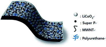
Fig. 1 shows a schematic of the free-standing electrode, with the MWNTs and PU homogeneously distributed and the vacant spaces filled with LCO and Super P. We also prepared a control free-standing electrode without MWNTs to investigate the effects of MWNT addition; this electrode was composed of LCO![[thin space (1/6-em)]](https://www.rsc.org/images/entities/char_2009.gif) :
:![[thin space (1/6-em)]](https://www.rsc.org/images/entities/char_2009.gif) Super P
Super P![[thin space (1/6-em)]](https://www.rsc.org/images/entities/char_2009.gif) :
:![[thin space (1/6-em)]](https://www.rsc.org/images/entities/char_2009.gif) PU at 77
PU at 77![[thin space (1/6-em)]](https://www.rsc.org/images/entities/char_2009.gif) :
:![[thin space (1/6-em)]](https://www.rsc.org/images/entities/char_2009.gif) 11.5
11.5![[thin space (1/6-em)]](https://www.rsc.org/images/entities/char_2009.gif) :
:![[thin space (1/6-em)]](https://www.rsc.org/images/entities/char_2009.gif) 11.5 (wt%). In order to examine the effect of the binder type, another free-standing electrode composed of LCO
11.5 (wt%). In order to examine the effect of the binder type, another free-standing electrode composed of LCO![[thin space (1/6-em)]](https://www.rsc.org/images/entities/char_2009.gif) :
:![[thin space (1/6-em)]](https://www.rsc.org/images/entities/char_2009.gif) Super P + MWNT
Super P + MWNT![[thin space (1/6-em)]](https://www.rsc.org/images/entities/char_2009.gif) :
:![[thin space (1/6-em)]](https://www.rsc.org/images/entities/char_2009.gif) PVDF at 77
PVDF at 77![[thin space (1/6-em)]](https://www.rsc.org/images/entities/char_2009.gif) :
:![[thin space (1/6-em)]](https://www.rsc.org/images/entities/char_2009.gif) 11.5
11.5![[thin space (1/6-em)]](https://www.rsc.org/images/entities/char_2009.gif) :
:![[thin space (1/6-em)]](https://www.rsc.org/images/entities/char_2009.gif) 11.5 (wt%) was fabricated, with the slurry dried at 110 °C for 30 min in a convection oven. The samples are denoted according to their constituents and composition and summarized in Table 1 along with the fabrication methods.
11.5 (wt%) was fabricated, with the slurry dried at 110 °C for 30 min in a convection oven. The samples are denoted according to their constituents and composition and summarized in Table 1 along with the fabrication methods.
| Type | Sample name | Binder | Composition (wt%) | |||
|---|---|---|---|---|---|---|
| LCO | Binder | Super P | MWNT | |||
| Metal-based | Al-PU | PU | 90 | 5 | 5 | 0 |
| Al-PVDF | PVDF | 90 | 5 | 5 | 0 | |
| Free-standing | FS-PU11.5-CNT00 | PU | 77.0 | 11.5 | 11.5 | 0 |
| FS-PU11.5-CNT50 | PU | 77.0 | 11.5 | 5.75 | 5.75 | |
| FS-PU17.9-CNT50 | PU | 71.4 | 17.9 | 5.35 | 5.35 | |
| FS-PU20.7-CNT50 | PU | 69.0 | 20.7 | 5.15 | 5.15 | |
| FS-PU24.6-CNT50 | PU | 65.6 | 24.6 | 4.90 | 4.90 | |
| FS-PVDF11.5-CNT50 | PVDF | 77.0 | 11.5 | 5.75 | 5.75 | |
Electrochemical analysis of the electrodes
First, we tested the compatibility of PU with common organic solvents used in LIB electrolytes and the test results are summarized in Table 2. Following these tests, a solution of 1.0 M LiBF4 in propylene carbonate (PC) was chosen as the electrolyte for further work and a glass-fibre separator was used. Coin-type half cells (CR2032) were fabricated in an Ar-filled glovebox to investigate the electrochemical properties of the electrodes, with lithium metal used as the counter electrode. The electrochemical measurements were conducted in a 3.0–4.3 V (vs. Li+/Li) potential range, with the cells charged and discharged in constant current (CC)/constant voltage (CV) and CC modes, respectively. The rate capability of the electrodes was examined at various current densities from 0.1 to 5C and the cycling stability of the electrodes was measured at constant current density of 0.5C during charging and 1C during discharging.| PC | EC/DEC | EC/EMC | AN | DOL/DME | |
|---|---|---|---|---|---|
| a PC: propylene carbonate, EC: ethylene carbonate, DEC: diethyl carbonate, EMC: ethylmethyl carbonate, AN: acetonitrile, DOL: dioxolane, DME: dimethyl ether. | |||||
| Solubility of polyurethane | Insoluble | Soluble | Soluble | Soluble | Soluble |
Mechanical properties
The stretchability of the free-standing electrodes was estimated using tensile strength measurements conducted with mechanical testing equipment (Instron 5960). The test specimens were prepared at a size of 20 mm (L) × 10 mm (W) × 50 μm (T) and pulled at a constant strain rate of 1 mm min−1 until they cracked.Results and discussion
Effect of binder type and peel strength
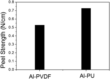
Fig. 2 shows the adhesive strength of the two metal-based electrodes fabricated with different binders. The electrode prepared with PU binder exhibited a higher adhesive strength, by approximately 0.5 N, than that prepared with PVDF. The better adhesive properties of PU compared with PVDF indicates that PU can be used as a polymeric binder for LIB electrodes.18,19Electrochemical properties of the metal-based electrodes
Initial charge/discharge curves of the two metal-based electrodes fabricated with different binders are displayed in Fig. 3(a). The electrodes prepared with PVDF binder (Al-PVDF) and PU binder (Al-PU) produced almost identical charge/discharge profiles.The initial charge and discharge capacities of Al-PVDF were 159.6 mA h g−1 and 153.6 mA h g−1, respectively, and those of Al-PU were 157.7 mA h g−1 and 153.6 mA h g−1, respectively. The rate capability of the two metal-based electrodes was measured at various current densities from 0.1 to 5C, as shown in Fig. 3(b). Even at high C-rates the two metal-based electrodes did not show any distinct difference in capacity, exhibiting only ∼1.1% difference in discharge capacity at 5C.
The cycling stabilities of the metal-based electrodes were tested at a constant current density (0.5C charge/1.0C discharge) and at both ambient (25 °C) and elevated (45 °C) temperatures. As shown in Fig. 3(c) and (d), the electrodes did not exhibit a clear difference in cycling stability after 100 cycles. The discharge-capacity retention rates (vs. 1st discharge capacity) of the Al-PVDF and Al-PU electrodes at ambient temperature were 98.1% and 98.3%, respectively. Similarly, there was no distinguishable difference at 45 °C, with discharge-capacity retention rates of 94.5% and 95.4% for the Al-PVDF and Al-PU electrodes, respectively.37 Based on these results, we do not anticipate any significant problems when using PU as a binder in LIB electrodes and expect that PU will be one of the most promising candidates as an electrode binder for flex-LIBs owing to its unique softness and flexibility.
Mechanical properties and micro-structure of the free-standing electrodes
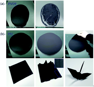
Photographs of the free-standing electrode fabrication procedure are shown in Fig. 4. After casting on the glass substrate, the slurry containing 11.5 wt% of PVDF (FS-PVDF11.5-CNT50) cracked during drying of the solvent (NMP) (Fig. 4(a)). It was impossible to further analyse this electrode due to its poor mechanical properties.Conversely, the slurry containing an equivalent amount of PU (FS-PU11.5-CNT50) produced a smooth electrode without cracks, and the film was very easily detached from the glass substrate.38 FS-PU11.5-CNT50 exhibited excellent mechanical stability even under folding. A free-standing electrode could be usually obtained only when using >20 wt% of PVDF binder. These results indicate that PU can form flexible free-standing electrodes with much smaller amounts of binder than PVDF, which makes it possible to prepare high-energy-density flexible electrodes.
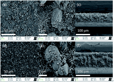
Fig. 5(a–c) shows scanning electron micrographs of the FS-PU11.5-CNT50 electrode. The LCO and Super P particles are uniformly distributed along the network provided by the MWNTs and PU throughout the electrode (Fig. 5(a) and (b)). The uniform distribution was also confirmed by a cross-sectional area micrograph of the electrode (Fig. 5(c)). In contrast, many pores were observed among the homogeneously-dispersed LCO and Super P particles on the free-standing electrode without MWNTs (FS-PU11.5-CNT00), both in the surface and cross-sectional micrographs (Fig. 5(d)–(f)). These pores are expected to prevent electron transport within the electrode and adversely affect its mechanical properties.
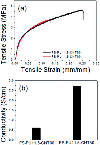
We also compared the tensile strength and electronic conductivity of the free-standing electrodes and found that adding MWNTs had a clear effect. Stress–strain curves of the free-standing electrodes are presented in Fig. 6(a); it is evident that adding MWNTs improves the mechanical properties of the electrode. FS-PU11.5-CNT00 showed only 13.1% elongation at a tensile stress of 3.73 MPa, while FS-PU11.5-CNT50 exhibited 24.9% elongation at the same load and broke at 4.63 MPa. In other words, we found that adding MWNTs to the free-standing electrode doubled the tensile strain of the electrode at the maximum load. As mentioned previously, the FS-PU11.5-CNT00 electrode contains abundant pores, which prevent close contact between the binder and active material and reduce the binding area (Fig. 5(e)), thus diminishing the mechanical properties of the electrode. Meanwhile, fewer pores are found in the free-standing electrode containing MWNTs, such that the PU and MWNTs contact over a large area in a dense structure (Fig. 5(b)) and, thus, enhance the mechanical strength.39–41 The difference in structure is believed to be closely associated with the excellent mechanical strength of the FS-PU11.5-CNT50 electrode.
We also found that adding MWNTs increased the electronic conductivity of the free-standing electrode, as shown in Fig. 6(b). FS-PU11.5-CNT50 exhibited an electronic conductivity of 2.73 S cm−1, which is approximately 4.5 times that exhibited by FS-PU11.5-CNT00.35,36,38
The excellent elongation properties of the free-standing electrode indicate an enhanced impact performance against impact strength and this impact resistance demonstrates that the free-standing electrodes have good toughness.37 The good mechanical properties of the free-standing electrode induced by the PU binder and MWNTs lower the risk of it being damaged by external force and increase the electronic conductivity, which makes the free-standing electrode containing MWNTs and PU binder appropriate for use in flex-LIBs.
Electrochemical properties of the free-standing electrodes
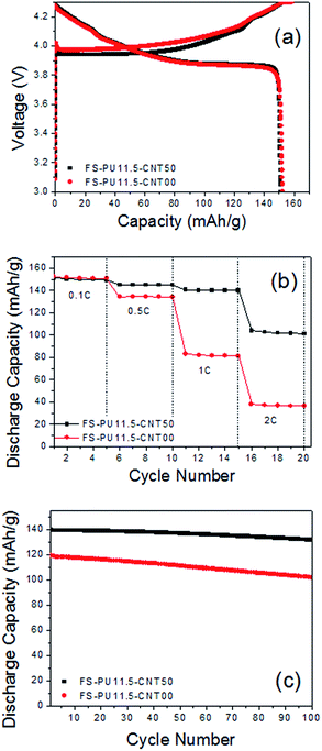
Fig. 7(a) and (b) shows the effect of MWNT addition on the rate capability of the free-standing electrode, as measured by varying the current density from 0.1 to 2C. We found that the initial capacities at low current density are similar irrespective of the presence of MWNTs. However, FS-PU11.5-CNT50 displayed a greater overpotential in the early stages of charging and delivered a higher capacity over a wide range of discharge current densities. FS-PU11.5-CNT50 retained a high discharge capacity of 101.08 mA h g−1 at 2C, while FS-PU11.5-CNT00 delivered only 36.5 mA h g−1.From these results, we believe that the increased electronic conductivity induced by MWNT addition improves the rate capability of the free-standing electrodes.
The cycling stability of the free-standing electrodes was tested at constant charge and discharge current densities of 0.5C and 1C, respectively, and ambient temperature; the results are displayed in Fig. 7(c). The cycling stability greatly improved upon addition of MWNTs to the electrode. The FS-PU11.5-CNT50 electrode retained 94.29% of its initial capacity after 100 cycles, while the retention rate of the FS-PU11.5-CNT00 electrode was only 85.40%. This difference is related with the non-uniform distribution of the conductive agent.42,43 It is most difficult to obtain the uniform distribution of nanometer sized Super P and this results in severe polarization and capacity loss.
We adjusted the amount of PU binder in the electrode to examine its effect on the mechanical strength, electronic conductivity and electrochemical performance. The amount of PU in the free-standing electrodes was varied from 11.5 to 24.6 wt%, with the full electrode compositions listed in Table 1. The amount of conductive agent was maintained almost constant to control its effect on the electrochemical performance.
Fig. 8(a) represents the electronic conductivity of the free-standing electrodes with different PU contents. We found that the conductivity increases with decreasing content of the binder. Liu et al. have reported that free polymer which is not immobilized on the surface of conductive carbon or active material plays a great role in determining the electronic conductivity of the electrodes.44 In this study, enough free polymer is expected to exist among the particles of the active material and conductive carbon in the electrode as the binder content is at least 11.5 wt% and the fraction of the active material is in the range of 65–77 wt%, which is not so high content to cause the aggregation of the conductive carbon particles stripping the fixed binder layer on the surface of carbon particles. In this case, the excess free polymer is expected to exert an impedance effect on the surface of the active material to slow down the lithium-ion transport at the interface as described in the literature. We also prepared free-standing electrodes at lower PU content than 11.5 wt% (5.0 and 8.0 wt%) and measured the electronic conductivity of these electrodes. The free-standing electrode with 8.0 wt% of PU content showed slightly higher conductivity than that with 11.5 wt% but we could not measure the conductivity at 5.0 wt% of PU content because the electrode was too weak to fabricate a free-standing electrode.
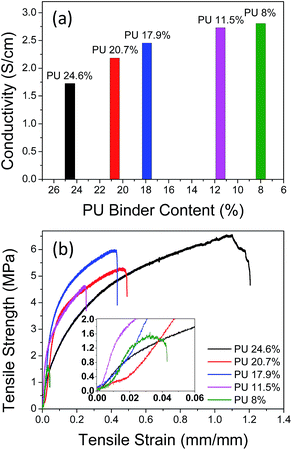 | ||
| Fig. 8 Effect of the PU-binder content on the electronic conductivity (a) and tensile strength (b) of the free-standing electrodes. | ||
Stress–strain curves of the free-standing electrodes with varying amount of PU are presented in Fig. 8(b). It was found that the mechanical strength of the free-standing electrode was enhanced with increasing amount of the binder content. The role of the free binder content is also believed to be very important to determine the mechanical properties of the electrode even though the effect is difficult to be quantitatively evaluated. At high PU content, the amount of free polymer increases and it would contribute to enhance the mechanical strength including the tensile strength and resistance against bending and folding while lowering the electronic conductivity.
From these results, we found that the formulation and distribution of the binder significantly affect the mechanical strength and electronic conductivity.
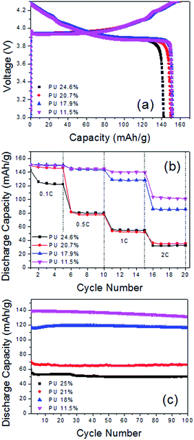
Fig. 9(a) shows the initial discharge capacity of the free-standing electrodes with varying amounts of PU. Decreasing the amount of PU from 24.6 wt% to 17.9 wt% resulted in an increased discharge capacity from 142.26 mA h g−1 to 151.30 mA h g−1. Further decreasing the amount of PU did not appear to influence the discharge capacity; FS-PU11.5-CNT50, FS-PU17.9-CNT50, and FS-PU20.7-CNT50 displayed similar capacities of approximately 151 mA h g−1.
Fig. 9(b) displays the discharge capacities of the free-standing electrodes containing different amounts of PU at various current densities. Similar to the trend seen at low current density, the electrode with the lowest PU content clearly displayed the highest discharge capacity at all tested current densities. FS-PU20.7-CNT50 showed slightly a lower discharge capacity than FS-PU11.5-CNT50 and FS-PU17.9-CNT50 at the low current density of 0.1C but it exhibited a similar performance to FS-PU24.6-CNT50 at increased current densities. The intrinsically high resistance of PU may be the cause of the low discharge capacities seen in the high-PU-content free-standing electrodes.
Fig. 9(c) shows the cycling stability of the free-standing electrodes with different PU contents. Similar to the rate capability results, the capacity retention rate of the free-standing electrodes after 100 cycles increased from 84.54% to 97.49% on decreasing the amount of PU from 24.6 wt% to 17.9%. FS-PU11.5-CNT50 showed a slightly smaller capacity retention rate (∼94.29%) than that of FS-PU17.9-CNT50. The free-standing electrodes with PU contents >20 wt% also displayed unstable cycling.
In order to validate the practicability of the free-standing electrodes, we calculated their energy densities and compared them with those of the Al-PVDF metal-based electrode; the results are shown in Table 3. When calculating energy densities, the weight of the Al was included for Al-PVDF, while the weight of current collector was excluded for the PU-based free-standing electrodes. The energy density of the FS-PU11.5-CNT50 electrode is comparable to that of the Al-PVDF electrode and it decreased with increasing PU binder content. Given that the free-standing electrodes are not optimally designed, there is room for further improvement in their energy density. Increasing the thickness of the free-standing electrodes would result in lower energy densities than the metal-based electrode, because they have a lower active-material (LCO) loading level compared with the metal-based electrode. Therefore, we expect that the free-standing electrodes would have greater energy densities than the metal-based electrode when the electrodes are thin. However, we also need to find other ways to raise the loading level of the free-standing electrodes.
| Sample | Active material loading level (mg cm−2) | Electrode thickness (μm) | Energy density per volume (W h L−1) | Energy density (W h kg−1) |
|---|---|---|---|---|
| Al-PVDF | 9.00 | 54 | 925 | 360 |
| FS-PU11.5-CNT50 | 7.84 | 45 | 967 | 430 |
| FS-PU17.9-CNT50 | 6.22 | 45 | 767 | 400 |
| FS-PU20.7-CNT50 | 6.05 | 45 | 746 | 380 |
| FS-PU24.6-CNT50 | 6.00 | 45 | 740 | 360 |
We measured the charge/discharge capacity of the cell fabricated with the free-standing electrode that was folded 10 times to examine the tolerance of the electrodes to repeated folding. As can be shown in Fig. 10(a), we could not found any distinct difference in capacity after folding. At the same time, we also measured the electronic conductivity of the free-standing electrode after 10 times of folding or stretching and the data are shown in Fig. 10(b). The electronic conductivities of the free-electrodes almost did not change after folding or stretching as can be seen in this figure.
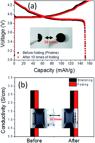 | ||
| Fig. 10 (a) Charge/discharge capacity after 10 times of folding/unfolding and (b) electronic conductivity after 10 times of folding/unfolding or stretching. | ||
Finally, we fabricated a full cell with the FS-PU11.5-CNT50 free-standing electrode and used it to light an LED (Fig. 11). We used a graphite anode that was prepared in the same way as the cathode. PU was used as the anode binder and MWNTs were also added to the anode. The LED was lighted by the full-cell even when bent.
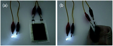 | ||
| Fig. 11 Demonstration of the FS-PU11.5-CNT50 free-standing electrode in a full-cell. Photographs of an LED lighted by the full-cell in (a) normal state and (b) bent state. | ||
These results led us to conclude that PU is a very promising binder for flex-LIBs because free-standing electrodes can be prepared with a much lower binder content when using PU instead of PVDF; PU also imparts excellent mechanical strength to the electrodes. Adding MWNTs to the free-standing electrodes overcomes the intrinsically poor electronic conductivity of PU. We believe that this study will contribute to the commercialization of flex-LIBs, though further efforts should be made to optimize various parameters including the electrode design and formulation.
Conclusions
Free-standing electrodes for use in flex-LIBs were fabricated using a PU binder and LCO active material. The electrode slurry was prepared by simple ball-milling in THF. We obtained the free-standing electrodes by casting the slurry on a glass substrate and then peeling off after drying. The tensile strength, bendability, and foldability of the electrodes were tested; the results indicated that the electrodes were mechanically robust. Adding MWNTs also provided the free-standing electrodes with good electrochemical properties including reversible capacity, rate capability and cycling stability which were comparable to metal-based electrodes. The free-standing electrode with added MWNTs exhibited a discharge capacity almost 3 times higher than that in the absence of MWNTs at a high current density of 2C. Adding MWNTs also improved the cycling stability by approximately 9% compared to the electrode without MWNT. We think that the network provided by uniform distribution of the MWNTs and PU is crucial to the enhanced mechanical strength and electronic conductivity. The FS-PU11.5-CNT50 electrode exhibited a tensile strength and an electronic conductivity that were 2 times and 4 times, respectively, higher than those of the FS-PU11.5-CNT00 electrode. The excellent mechanical and electrical properties resulted in the outstanding flexibility and electrochemical performance of the free-standing electrodes. From this study, we believe that free-standing electrodes fabricated with PU and MWNT are the most suitable for use in flex-LIBs.Notes and references
- J. Z. Wang, S. L. Chou, J. Chen, S. Y. Chew, G. X. Wang, K. Konstantinov, J. Wu, S. X. Dou and H. K. Liu, Electrochem. Commun., 2008, 10, 1781 CrossRef CAS.
- R. S. Morris, B. G. Dixon, T. Gennett, R. Raffaelle and M. J. Heben, J. Power Sources, 2004, 138, 277 CrossRef CAS.
- S. H. Ng, J. Wang, Z. P. Guo, J. Chen, G. X. Wang and H. K. Liu, Electrochim. Acta, 2005, 51, 23 CrossRef CAS.
- J. Chen, Y. Liu, A. I. Minett, C. Lynam, J. Wang and G. G. Wallace, Chem. Mater., 2007, 19, 3595 CrossRef CAS.
- L. Jabbour, M. Destro, D. Chaussy, C. Gerbaldi, N. Penazzi, S. Bodoardo and D. Beneventi, Cellulose, 2013, 20, 571 CrossRef CAS.
- S. Leijonmarck, A. Cornell, G. Lindbergh and L. Wågberg, Nano Energy, 2013, 2, 794 CrossRef CAS.
- V. L. Pushparaj, M. M. Shaijumon, A. Kumar, S. Murugesan, L. Ci, R. Vajtai, R. J. Linhardt, O. Nalamasu and P. M. Ajayan, Proc. Natl. Acad. Sci. U. S. A., 2007, 104, 13574 CrossRef CAS PubMed.
- L. Hu, J. W. Choi, Y. Yang, S. Jeong, F. La Mantia, L.-F. Cui and Y. Cui, Proc. Natl. Acad. Sci. U. S. A., 2009, 106, 21490 CrossRef CAS PubMed.
- Z. Chen, L. Christensen and J. R. Dahn, J. Electrochem. Soc., 2003, 150, A1073–A1078 CrossRef CAS.
- J. Li, R. B. Lewis and J. R. Dahn, Electrochem. Solid-State Lett., 2007, 10, A17–A20 CrossRef CAS.
- C. Sasso, E. Zeno and M. Petit, Macromol. Mater. Eng., 2010, 295, 934–941 CrossRef CAS.
- L. Jabbour, C. Gerbaldi, D. Chaussy and E. Zeno, J. Mater. Chem., 2010, 20, 7344–7347 RSC.
- Y. Liu, S. Gorgutsa and C. Santato, J. Electrochem. Soc., 2012, 159, A349–A356 CrossRef CAS.
- P. Santhosh, T. Vasudevan, A. Gopalan and K. P. Lee, Mater. Sci. Eng., B, 2006, 135, 65 CrossRef CAS.
- Y. L. Du and T. C. Wen, Mater. Chem. Phys., 2011, 71, 62 CrossRef.
- H.-H. Kuo, W.-C. Chen, T.-C. Wen and A. Gopalan, J. Power Sources, 2002, 110, 27 CrossRef CAS.
- L. Zhou, Q. Cao, B. Jing, X. Wang, X. Tang and N. Wu, J. Power Sources, 2014, 263, 118 CrossRef CAS.
- J.-S. Kim, Y.-H. Lee, I. Lee, T.-S. Kim, M.-H. Ryou and J. W. Choi, J. Mater. Chem. A, 2014, 2, 10862 CAS.
- Y. H. Lee, J. S. Kim, J. Noh, I. Lee, H. J. Kim, S. Choi, J. Seo, S. Jeon, T. S. Kim, J. Y. Lee and J. W. Choi, Nano Lett., 2013, 13, 5753 CrossRef CAS PubMed.
- Y. Kim, J. Zhu, B. Yeom, M. Di Prima, X. Su, J.-G. Kim, S. J. Yoo, C. Uher and N. A Kotov, Nature, 2013, 500, 59 CrossRef CAS PubMed.
- S. Weiner, O. Biomineralization, M. W. Ghosh and B. Urban, Science, 2009, 323, 1458 CrossRef PubMed.
- T. Sato, K. Banno, T. Maruo and R. Nozu, J. Power Sources, 2005, 152, 264 CrossRef CAS.
- J. D. Vanheumen and J. R. Stevens, Macromolecules, 1995, 28, 4268 CrossRef CAS.
- M. Digar, S. L. Hung, H. L. Wang, T. C. Wen and A. Gopalan, Polymer, 2001, 43, 681 CrossRef.
- H. J. Qi and M. C. Boyce, Mech. Mater., 2005, 37, 817 CrossRef.
- N. G. Sahoo, Y. C. Jung, H. J. Yoo and J. W. Cho, Compos. Sci. Technol., 2007, 67, 1920 CrossRef CAS.
- H. Deka, N. Karak, R. D. Kalita and A. K. Buragohain, Carbon, 2010, 48, 2013 CrossRef CAS.
- J. C. Zhao, F. P. Du, X. P. Zhou, W. Cui, X. M. Wang, H. Zhu, X. L. Xie and Y. W. Mai, Composites, Part B, 2011, 42, 2111 CrossRef.
- S. Gu, B. Yan, L. Liu and J. Ren, Eur. Polym. J., 2013, 49, 3867 CrossRef CAS.
- S. S. Mahapatra, S. K. Yadav, H. J. Yoo, M. S. Ramasamy and J. W. Cho, Sens. Actuators, B, 2014, 193, 384 CrossRef CAS.
- J. W. Cho, J. W. Kim, Y. C. Jung and N. S. Goo, Macromol. Rapid Commun., 2005, 26, 412 CrossRef CAS.
- H. Luo, Z. Li, G. Yi, X. Zu, H. Wang, H. Huang, Y. Wang, Z. Liang and S. Zhang, Mater. Lett., 2014, 137, 385 CrossRef CAS.
- R. Zhang, H. Deng, R. Valenca, J. Jin, Q. Fu, E. Bilotti and T. Peijs, Sens. Actuators, B, 2012, 179, 83 CrossRef CAS.
- P. Slobodian, P. Riha, R. Olejnik and P. Saha, Carbon, 2013, 1526, 268 CAS.
- J. Chen, Z. Xing Zhang, W. Bin Huang, J. le Li, J. Hui Yang, Y. Wang, Z. Wan Zhou and J. Hong Zhang, Mater. Des., 2015, 69, 105 CrossRef CAS.
- M. Raja, A. M. Shanmugharaj, S. H. Ryu and J. Subha, Mater. Chem. Phys., 2011, 129, 925 CrossRef CAS.
- N. Loeffler, T. Kopel, G.-T. Kim and S. Passerini, J. Electrochem. Soc., 2015, 162, 2692–2698 CrossRef.
- L. D. Tijing, C. H. Park, W. L. Choi, M. T. G. Ruelo, A. Amarjargal, H. R. Pant, I. T. Im and C. S. Kim, Composites, Part B, 2013, 44, 613–619 CrossRef CAS.
- H. C. Kuan, C. C. M. Ma, W. P. Chang, S. M. Yuen, H. H. Wu and T. M. Lee, Compos. Sci. Technol., 2005, 65, 1703–1710 CrossRef CAS.
- W. Chen, X. Tao and Y. Liu, Compos. Sci. Technol., 2006, 66, 3029–3034 CrossRef CAS.
- J. S. Jeong, J. S. Moon, S. Y. Jeon, J. H. Park, P. S. Alegaonkar and J. B. Yoo, Thin Solid Films, 2007, 515, 5136–5141 CrossRef CAS.
- J. H. Lee, S. B. Wee, M. S. Kwon, H. H. Kim, J. M. Choi, M. S. Song, H. B. Park, H. Kim and U. Paik, J. Power Sources, 2011, 196, 6449–6455 CrossRef CAS.
- R. Dominko, M. Gaberscek, J. Drofenik, M. Bele, S. Pejovnik and J. Jamnik, J. Power Sources, 2003, 119–121, 770–773 CrossRef CAS.
- G. Liu, H. Zheng, X. Song and V. S. Battaglia, J. Electrochem. Soc., 2012, 153, A214–A221 CrossRef.
| This journal is © The Royal Society of Chemistry 2017 |

