 Open Access Article
In situ growth of TiO2/SiO2 nanospheres on glass substrates via solution impregnation for antifogging†
Fang Liu a,
Jie Shenb,
Wuyi Zhou
 c,
Shiying Zhang*ab and
Long Wan*a
aCollege of Materials Science and Engineering, Hunan University, Changsha, 410082, PR China. E-mail: wanlong1799@163.com; cszhangsy@ccsu.edu.cn; Tel: +86-731-84261297
bHunan Key Laboratory of Applied Environmental Photocatalysis, Changsha University, Changsha, 410022, PR China
cCollege of Materials and Energy, South China Agricultural University, Guangzhou, 510642, China
First published on 13th March 2017
Abstract
Uniform TiO2/SiO2 nanospheres of 500 nm size were in situ fabricated on substrates by a facile soft templating route. The morphologies of the nanospheres on the substrates, as well as the intermediates, were evaluated by FESEM. During the synthesis, a micelle formation process transforming from rod-like micelles to vesicles to lamellar phases was proposed, attributed to the electrostatic self-assembly process of the oppositely charged cationic cetyltrimethyl-ammonium tosylate (CTATos) and anionic Si–OH in the solution. The processed substrates are transparent and super-hydrophilic with good antifogging properties. The homogeneous growth, firm substrate combination, and facile procedures are significantly advantageous for the fabrication method and can be explored with other substrates such as modified electrodes and nanoscale devices for diverse applications.
Introduction
Super-hydrophilic coatings, made of polymers or metal oxides, have great potential for anti-fogging, self-cleaning, anti-fouling, fog-harvesting and so on.1–9 The super-hydrophilicity can be fabricated either by micro-/nano-scale structure or by high surface concentrations of functional (e.g., hydroxyl) groups.10–17 Silica is one of the widely used super-hydrophilic materials with superior transparency and anti-fogging performance due to the high surface concentration of hydroxyl groups. Meanwhile, TiO2 is also widely used for antifogging as the thin sol–gel made polycrystalline films because of its UV-induced super-hydrophilicity.18 Combining the two metal oxides (SiO2 and TiO2), X. Li reported raspberry-like SiO2–TiO2 nanoparticle antireflective coatings with superhydrophilicity, high transmittances and good photocatalytic decomposition toward organics.19 Z. Wu et al. reported porous SiO2/TiO2 Bragg stacks exhibiting potentially useful superhydrophilicity and self-cleaning properties.20Because of increasing demand of advanced materials with high-tech applications, the development of ceramic nanoparticles has drawn significant attention. Submicron silica particles had been produced and widely used in scientific and industrial applications such as catalysis, electronic, thin film substrate, anti-fogging coating, humidity sensors, and biomedical nanocarriers, because of the controllable size, good monodispersity, favorable biological compatibility, and easy surface modification, as the typical example in advanced ceramic.21–23 Thus, the synthesis and surface modification of the monodispersed and narrow-sized silica particles have been successfully achieved by the sol–gel method, reverse microemulsion, flame synthesis and so on.24–26
Among these methods, the sol–gel process is widely utilized for the preparation of nanocomposites owing to its excellent control of the particle size, monodispersion and well-defined morphology, with the representative of the classical work by Stöber et al.27 Since Grün et al. first obtained the submicron MCM-41, the modified Stöber method has been proposed.28 Based upon a Stöber-like approach, the synthetic compositions can be modified by adding the cationic surfactant into the existing reactants (tetraalkyl silicates, alcohol, water and ammonia) to prepare the uniform mesoporous silica nanoparticles.29–31 Because the phase of the cationic surfactant can transform among spherical micelles, cylindrical micelles and vesicles in the solution system as the soft template, the silica nanoparticles with various morphologies and mesostructures, such as dual-mesoporous, core–shell and hollow silica nanoparticles have been synthesized.32–36
Though the silica nanoparticles can be prepared and applied flexibly, the particle assembly on the substrate is still a real problem. To solve this problem, in situ growth method without the follow-up has been used extensively for graphene-like structure, thin films, nanocrystals, metal particles and quantum dots, owing to significant advantages of the interfacial bonding strength.37–42 However, in situ growth of nanospheres on the glass substrates is scarcely reported. Herein, we proposed a facile strategy to synthesize TiO2/SiO2 nanospheres on the glass substrates combining in situ growth and the modified Stöber method. The prepared nanospheres with a diameter of ∼500 nm were uniformly grown on the substrates, exhibiting a super-hydrophilic property suitable for antifogging.
Experimental
Materials
In this study, all reagents were used directly without further purification. Tetrabutyl orthotitanate (TBOT), tetraethyl orthosilicate (TEOS), acetyl acetone, n-butanol, nitric acid, ammonia (28 wt%) and absolute ethyl alcohol were all A.R and provided by Sinopharm Group Co. Ltd, China. The CTATos (cetyltrimethylammonium tosylate) used in the experiment were purchased from Sigma Corporation of America. The glass slides substrates were also obtained from Sinopharm Group Co. Ltd, which should be washed by absolute ethyl alcohol and deionized water alternately three times under ultrasonic processing and then dried in an oven at 80 °C. Deionized water used all over the experiment was self-made in the laboratory.Synthetic procedures
Characterization
The morphologies of the in situ growing particles on the substrate were evaluated by field emission scanning electron microscopy (FESEM, JSM-6700F, SHIMADZU). The composition of the TiO2/SiO2 nanospheres was detected by the Energy Dispersive Spectrometer (EDS). Finally, the contact angles of the membranes were measured by a JC2000D2 Tensiometer and Contact Angle Meter.Results and discussion
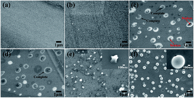
The morphologies of the in situ growth samples were examined by FESEM, as shown in Fig. 1. The images displayed that the blank substrate was flat and smooth, the simple TEOS assembling making no much change, seen in Fig. 1a and b. As displayed in Fig. 1c, the spherical siloxane particles in situ grew on the TEOS assembled substrate after 48 h immersing in the modified Stöber solution. As the red arrows indicated, most of the siloxane spheres were imperfect and appeared the hollow structure, due to the syneresis of the templates. In view of this, we perceived that the cationic surfactant CTATos might form a vesicles phase in the solution as the soft template for the hollow cavity.43,44 With coated by the prepared titanium gel, as shown in Fig. 1d, the spherical siloxane particles were filled and encapsulated to be the complete spheres. After a heat treatment of 500 °C, the structure of the TiO2/SiO2 nanospheres were still complete kept as exhibited in Fig. 1f, whereas the fragile spherical silica particles were collapsed to be small protuberances without the titanium coating, shown in Fig. 1e. The size shrinkage of the TiO2/SiO2 nanospheres can be attributed to the thermal condensation of silica and titanium.To show the homogeneous growth of the TiO2/SiO2 nanospheres on the substrate, the macrograph of FESEM was provided in Fig. 2a. The elemental analysis was also tested by EDS (Fig. 2b) and the alveolate inner cavity of the nanospheres was shown in the inset graph. From the EDS graph, the peaks of Si, O and Ti introduced by the experiment were observed. The other elements like Na, Mg, Al and Ca could be attributed to the composition of the glass substrate. The element Pt was attributed to the metal spraying before the FESEM test.
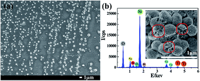 | ||
| Fig. 2 The macrograph (a), the EDS analysis (b) and the broken cavity (inset) of the TiO2/SiO2 nanospheres. | ||
The EDS analysis of the unheated TiO2/SiO2 nanospheres has been provided in the ESI file as Fig. S1,† from which the distinct peak of C was observed. Considering of the almost invisible peak of C in the heated sample (Fig. 2b), it can be perceived that the carbon in the system was almost completely removed. What's more, the element distribution (Ti, Si and C) from EDS mapping of the TiO2/SiO2 nanospheres before and after the calcination treatment has been provided in the ESI file as Fig. S2.† As shown in Fig. S2,† the carbon element concentrated in the cavity of the nanospheres before the calcination and disappeared after the heat treatment. The result proved the spherical multilamellar vesicle template structure forming the lamellar phases in the immersing solution and the complete removal of the template after the calcination treatment.
To further investigate the in situ growing mechanism of the silica particles in the immersing solution, the SiO2 samples with different immersing time were observed using FESEM and the results were shown in Fig. 3. The in situ growing processes of the silica particles in the immersing solution were exhibited explicitly in Fig. 3a–d. At the initial 6 h, the scattered silica particles dispersed on the substrate and some of them assembled the rod-like nicks. Going through another 6 h, the silica particles assembled as several circular holes which seemed like the surface was engraved by spherical templates. After 24 h immersing, the silica particles tended to grow upwards from the edge of the circle and finally formed a bowl-like structure. After immersed for 48 h, the particles grew to the complete spherical structure, combining with Fig. 1c, and collapsed to be protuberances with heat treatment. In addition, the average size of rod-like silica particles is at the length of about 125 nm and diameter of 15 nm from the heated sample SP6 (as seen in Fig. S3†). The size of the circular holes is about 500 nm from the heated sample SP12 (Fig. 3b). The size of the bowl-like structure is about 300 nm from the heated sample SP24 (Fig. 3c). The size of the spherical structure is about 800 nm from the un-heating SP48 (Fig. 1c).
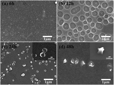 | ||
| Fig. 3 FESEM images of the in situ growing SiO2 particles with different immersing time. Based on the immersing time, the images of SP6 (a), SP12 (b), SP24 (c) and SP48 (d) were shown respectively. | ||
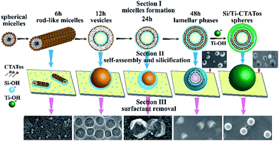
Based on the incremental immersing FESEM images, the in situ synthesis mechanism of the TiO2/SiO2 nanospheres was investigated in Fig. 4. Due to the perceived point, the gradual micelle formation was the critical step in the synthesis. Inspired by the work of L. Han et al.,45 the single-tailed anionic surfactants and the cationic silane producing lamellar phases to prepare the silica nanospheres with diameter of 300 nm, the oppositely charged cationic CTATos and anionic Si–OH might also form the vesicles and lamellar phases in this experiment. At the initial 6 h, the cationic CTATos was used as the template and several rod-like micelles were formed in the immersing solution.46 With the gradually hydrolyzing of the adhering silane, the increased anionic Si–OH combined CTATos to form the vesicles at 12 h.47 As time passed, the Si–OH aggregated and condensed along the cationic vesicles, finally forming the lamellar phases by layer-by-layer electrostatic self-assembly of Si–OH and CTATos in the immersing solution and depositing on the substrate surface.48 The hydrolyzed silane further condensed around the lamellar micelles, and produced the hollow spherical organic silica structures on the substrate after immersing for 48 h.49 As the concentration of Si–OH decreased with distance from the substrate, lots of spherical silica structures were incomplete, and the vulnerable silica layers collapsed easily after heat treatment. The titanium gel was coated before heat-treatment to keep the complete spherical structures, and the gel might fill the hollow cavity partly (shown in the inset of Fig. 2b) because of the high solubility of CTATos in gel solution.
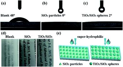
The wettability of the processed substrates was detected via the contact angle test. As shown in Fig. 5a–c, the unprocessed substrate possessed a contact angle (CA) of 48°, whereas a good super-hydrophilicity was exhibited after the in situ modification (CA < 5°). Benefiting from the super-hydrophilicity, the processed substrates exhibited good antifogging properties, as shown in Fig. 5d. The in situ synthesized SiO2 particles and TiO2/SiO2 nanospheres distributed on the substrates to form a rough topography as shown in Fig. 5e. In addition with the hydrophilic chemical composition, the super-hydrophilic surface was finally prepared.50
Conclusions
In this study, we have developed a facile soft templating route for in situ fabrication of TiO2/SiO2 nanospheres on the glass substrates. During the solution impregnation in synthesis, a micelles formation process transforming from rod-like micelles to vesicles to lamellar phases was assumed based on the incremental immersing FESEM images. The micelles formation mechanism was investigated as the unique layer-by-layer electrostatic self-assembly process of the oppositely charged cationic CTATos and anionic Si–OHs in the solution. The hydrolyzed silane finally condensed around the lamellar micelles, affording spherical structures. The prepared TiO2/SiO2 nanospheres had a uniform dimension of ∼500 nm. The homogeneous growth and firm substrate combination provides significant advantage for in situ fabrication compared to traditional nanopowder coatings. The processed substrates are transparent and super-hydrophilic, possessing good antifogging property. As the in situ fabrication can be achieved via simple modified Stöber solution impregnation at room temperature, the synthetic method can be easily explored to other substrates such as modified electrode and nano-scale devices, for diverse applications.Acknowledgements
We are grateful for the financial support from the National Natural Science Foundation of China (51272032), the Hunan Provincial Natural Science Foundation of China (14JJ5010), the Graduate Student Research Innovation Project in Hunan Province (No. 022900/521293321) and the Aid Program for Science and Technology Innovative Research Team in Higher Educational Institutions of Hunan Province.Notes and references
- X. Tang, T. Wang, F. Yu, X. Zhang, Q. Zhu, L. Pang, G. Zhang and M. Pei, RSC Adv., 2013, 3, 25670–25673 RSC.
- Q. Mao, D. Zeng, K. Xu and C. Xie, RSC Adv., 2014, 4, 58101–58107 RSC.
- I. You, Y. C. Seo and H. Lee, RSC Adv., 2014, 4, 10330–10333 RSC.
- S. Nishimoto and B. Bhushan, RSC Adv., 2012, 3, 671–690 RSC.
- D. Tahk, T. Kim, H. Yoon, M. Choi, K. Shin and K. Y. Suh, Langmuir, 2010, 26, 2240–2243 CrossRef CAS PubMed.
- P. Patel, K. C. Chang and D. D. Meng, JALA, 2010, 15, 114–119 CAS.
- R. P. Garrod, L. G. Harris, W. C. Schofield, J. Mcgettrick, L. J. Ward, D. O. Teare and J. P. Badyal, Langmuir, 2007, 23, 689–693 CrossRef CAS PubMed.
- M. L. Carman, T. G. Estes, A. W. Feinberg, J. F. Schumacher, W. Wilkerson, L. H. Wilson, M. E. Callow, J. A. Callow and A. B. Brennan, Biofouling, 2006, 22, 11–21 CrossRef CAS PubMed.
- R. Blossey, Nat. Mater., 2003, 2, 301–306 CrossRef CAS PubMed.
- F. Dai, M. Zhang, B. Hu, Y. Sun, Q. Tang, M. Du and X. Zhang, RSC Adv., 2015, 5, 3574–3580 RSC.
- J. Liu, F. Chen, H. Zheng, S. Liu, J. Sun, S. Huang, J. Song, Z. Jin and X. Liu, RSC Adv., 2016, 6, 79437–79447 RSC.
- T. Li, J. Shen, Z. Zhang, S. Wang and D. Wei, RSC Adv., 2016, 6, 40656–40663 RSC.
- V. A. Ganesh, A. S. Nair, H. K. Raut, T. M. Walsh and S. Ramakrishna, RSC Adv., 2011, 2, 2067–2072 RSC.
- J. Zhao, A. Meyer, L. Ma, X. Wang and W. Ming, RSC Adv., 2015, 5, 102560–102566 RSC.
- W. Zhang, L. Zhu, W. Li, H. Ye and H. Liu, RSC Adv., 2016, 6, 92252–92258 RSC.
- H. Xu, L. Liu, F. Wu, D. Xu and N. Lu, RSC Adv., 2015, 5, 28014–28018 RSC.
- B. Dudem, J. W. Leem and J. S. Yu, RSC Adv., 2015, 6, 3764–3773 RSC.
- W. Y. Wong, N. Nasiri, A. Rodriguez, D. Nisbet and A. Tricoli, J. Mater. Chem. A, 2014, 2, 15575–15581 RSC.
- X. Li and J. He, ACS Appl. Mater. Interfaces, 2013, 5, 5282–5290 CrossRef CAS PubMed.
- Z. Wu, L. Daeyeon, R. Michael and C. Robert, Small, 2007, 3, 1445–1451 CrossRef CAS PubMed.
- I. A. Rahman and V. Padavettan, J. Nanomater., 2012, 2012, 2817–2827 Search PubMed.
- Z. Li, J. C. Barnes, A. Bosoy, J. F. Stoddart and J. I. Zink, Chem. Soc. Rev., 2012, 41, 2590–2605 RSC.
- F. C. Cebeci, Z. Wu, L. Zhai, R. E. Cohen and M. F. Rubner, Langmuir, 2006, 22, 2856–2862 CrossRef CAS PubMed.
- Q. H. Zeng, D. Z. Wang, A. B. Yu and G. Q. Lu, Nanotechnology, 2002, 13, 549–553 CrossRef CAS.
- T. T. Y. Tan, S. Liu, Y. Zhang, M. Y. Han and S. T. Selvan, Comprehensive Nanoscience & Technology, 2011, vol. 5, pp. 399–441 Search PubMed.
- E. Reverchon and R. Adami, J. Supercrit. Fluids, 2006, 37, 1–22 CrossRef CAS.
- W. Stöber, A. Fink and E. Bohn, J. Colloid Interface Sci., 1968, 26, 62–69 CrossRef.
- M. Grün, I. Lauer and K. K. Unger, Adv. Mater., 1997, 9, 254–257 CrossRef.
- Y. Lin, C. Tsai, H. Huang, C. Kuo, Y. Hung, D. Huang, A. Yaochang Chen and C. Mou, Chem. Mater., 2005, 17, 1–6 CrossRef.
- K. Yano and Y. Fukushima, J. Mater. Chem., 2004, 14, 1579–1584 RSC.
- T. Nakamura, M. Mizutani, H. Nozaki, N. Suzuki and K. Yano, J. Phys. Chem. C, 2007, 165, 1093–1100 CrossRef.
- Y. Q. Yeh, B. C. Chen, H. P. Lin and C. Y. Tang, Langmuir, 2006, 22, 6–9 CrossRef CAS PubMed.
- T. Suteewong, H. Sai, R. Cohen, S. Wang, M. Bradbury, B. Baird, S. M. Gruner and U. Wiesner, J. Am. Chem. Soc., 2011, 133, 172–175 CrossRef CAS PubMed.
- J. Liu, Q. Yang, L. Zhang, H. Yang, J. Gao and C. Li, Chem. Mater., 2008, 20, 4268–4275 CAS.
- J. Liu, S. Z. Qiao, S. Budi Hartono and G. Q. Lu, Angew. Chem., Int. Ed., 2010, 49, 4981–4985 CrossRef CAS PubMed.
- T. W. Kim, P. W. Chung and S. Y. Lin, Chem. Mater., 2010, 22, 5093–5104 CrossRef CAS.
- G. Xi, J. Ye, Q. Ma, N. Su, H. Bai and C. Wang, J. Am. Chem. Soc., 2012, 134, 6508–6511 CrossRef CAS PubMed.
- Z. Teng, G. Zheng, Y. Dou, W. Li, C. Y. Mou, X. Zhang, A. M. Asiri and D. Zhao, Angew. Chem., Int. Ed., 2012, 51, 2173–2177 CrossRef CAS PubMed.
- F. Liu, L. Yi, K. Zhang, W. Bo, Y. Chang, Y. Lai, Z. Zhang, L. Jie and Y. Liu, Sol. Energy Mater. Sol. Cells, 2010, 94, 2431–2434 CrossRef CAS.
- H. Lee, S. W. Yoon, E. J. Kim and J. Park, Nano Lett., 2007, 7, 778–784 CrossRef CAS PubMed.
- F. Gong, H. Wang, X. Xu, G. Zhou and Z. S. Wang, J. Am. Chem. Soc., 2012, 134, 10953–10958 CrossRef CAS PubMed.
- H. Chang, X. Lv, H. Zhang and J. Li, Electrochem. Commun., 2010, 12, 483–487 CrossRef CAS.
- H. Yin, Z. Zhou, J. Huang, R. Zheng and Y. Zhang, Angew. Chem., Int. Ed., 2003, 42, 2188–2191 CrossRef CAS PubMed.
- L. Pan, Q. He, J. Liu, Y. Chen, M. Ma, L. Zhang and J. Shi, J. Am. Chem. Soc., 2012, 134, 5722–5725 CrossRef CAS PubMed.
- L. Han, C. Gao, X. Wu, Q. Chen, P. Shu, Z. Ding and S. Che, Solid State Sci., 2011, 13, 721–728 CrossRef CAS.
- K. Zhang, L. L. Xu, J. G. Jiang, N. Calin, K. F. Lam, S. J. Zhang, H. H. Wu, G. D. Wu, B. Albela and L. Bonneviot, J. Am. Chem. Soc., 2013, 135, 2427–2430 CrossRef CAS PubMed.
- P. Kipkemboi, A. Fogden, A. Viveka Alfredsson and K. Flodström, Langmuir, 2001, 17, 5398–5402 CrossRef CAS.
- H. P. Hentze, S. R. Raghavan, M. Kelvey and E. W. Kaler, Langmuir, 2003, 19, 1069–1074 CrossRef CAS.
- J. Liu, S. B. Hartono, Y. G. Jin, Z. Li, G. Q. Lu and S. Z. Qiao, J. Mater. Chem., 2010, 20, 4595–4601 RSC.
- B. Su, Y. Tian and L. Jiang, J. Am. Chem. Soc., 2015, 138, 1727–1748 CrossRef PubMed.
Footnote |
| † Electronic supplementary information (ESI) available: Magnification FESEM image, FT-IR spectra, EDS analysis, element distribution (Ti, Si and C) from EDS mapping and TEM image. See DOI: 10.1039/c6ra27276b |
| This journal is © The Royal Society of Chemistry 2017 |

