Highly efficient thermally activated delayed fluorescence materials with reduced efficiency roll-off and low on-set voltages†
Haobin
Zhao
,
Zhiheng
Wang
,
Xinyi
Cai
,
Kunkun
Liu
,
Zuozheng
He
,
Xin
Liu
,
Yong
Cao
and
Shi-Jian
Su
 *
*
State Key Laboratory of Luminescent Materials and Devices and Institute of Polymer Optoelectronic Materials and Devices, South China University of Technology, Guangzhou 510640, P. R. China. E-mail: mssjsu@scut.edu.cn
First published on 13th June 2017
Abstract
Two carbazoles or diphenylamines were combined with carbazole to obtain two branch-shaped donor units and then connected to a benzophenone unit, acquiring two donor–acceptor (D–A) type thermally activated delayed fluorescence (TADF) materials named CCDC and CCDD. CCDC and CCDD demonstrate opposing phenomena in a THF/H2O mixed solvent despite their structural similarity. The photoluminescence (PL) of CCDC drops drastically as the water proportion goes up, while the PL of CCDD increases with an increasing water ratio. The lower PL emission of CCDD in good solvents may be attributed to the vibration and rotation of the phenyl rings in the diphenylamine donors, and the PL emission increases when the intramolecular movement is restricted. However, PL quantum yield (PLQY) tests and device performances indicate that both materials experience aggregation-caused quenching (ACQ) to some extent in a solid state film. This is because when intramolecular vibration and rotation is restrained in the solid state, intermolecular stacking still hampers the fluorescence emission of CCDD. Also, the materials perform well in doped devices. A maximal external quantum efficiency (EQE) of 15.9% is achieved in blue-emitting devices with CCDC as the emitter. Green-emitting devices where CCDD is utilized as the emitter perform well regarding their overall properties. Not only do their maximal EQEs exceed 22%, but they also achieve on-set voltages as low as 2.6 V with a 30% doping concentration. Moreover, the efficiency roll-off of the CCDD-based devices is well controlled. An EQE of nearly 20% is maintained at a luminance of 1000 cd m−2.
Introduction
Studies on organic light-emitting diodes (OLEDs) have been carried out for over 30 years since their first breakthrough1 because of their promising potential applications in energy-efficient and high-resolution flat-panel displays, solid-state lighting, wearable electronics, etc.2–5 During electrical excitation, the probability of generating singlet excitons is 25% and the rest are triplet excitons. But the direct radiative decay of triplet excitons is prohibited in traditional fluorescent materials. Thus, a maximum of merely 25% of the excitons contribute to the emission. As for phosphorescent materials, both singlet and triplet excitons can be utilized for radiative emission owing to their enhanced spin–orbit interactions with the introduction of heavy metals like iridium and platinum. However, these noble metals are rare and costly, which seriously impedes the extensive industrialization of phosphorescent materials.6 In comparison, metal-free thermally activated delayed fluorescence (TADF) materials can also achieve 100% use of excitons through reverse intersystem crossing (RISC) because of their low energy gap (ΔEST) between the lowest singlet excited state (S1) and the triplet excited state (T1).There have been multiple reports of high-performance TADF materials in recent years since Adachi's breakthrough of reaching a maximal external quantum efficiency (EQE) of 19.3% with the green-emitting material 4CzIPN.7 DMAC-DPS was later introduced by the same group and achieved a maximal EQE of 19.5% with sky-blue emission.8 We also reported the high-performance evaporation- and solution-process feasible green-emitting material ACRDSO2 and yellow-emitting material PXZDSO2 with comparable efficiencies9 and a red-emitting material with well-controlled efficiency roll-off at a high current density.10 The high efficiencies achieved by TADF materials have proved their potential compared to their conventional fluorescent and phosphorescent counterparts. Nevertheless, for further application, a TADF material has to perform well in all aspects. It needs a high maximal EQE, low on-set voltage, well-controlled efficiency roll-off, good stability, etc., to be developed into a commercially applicable material.
In general, a low ΔEST is achieved with good separation between the highest occupied molecular orbital (HOMO) and the lowest unoccupied molecular orbital (LUMO) by decreasing the electron repulsion.11 Applicable approaches include the use of strong donors and acceptors, or enhancing the dihedral angles between the donor and acceptor units. However, both ways would induce drawbacks. The former promotes intramolecular charge transfer (ICT) and causes bathochromic shifts in emission, while a large dihedral angle significantly lowers the oscillator strength of molecules. Actually, complete separation of the HOMO and LUMO lowers the ΔEST at the expense of oscillator strength, while high oscillator strength is an indicator of a high rate constant for radiative decay.12 So, a balance between a reasonably low ΔEST and high oscillator strength has to be considered to achieve the good overall performance of a TADF material. Therefore, the ideal situation is that the HOMO and LUMO are mildly overlapped with moderately twisted donor and acceptor units. Moreover, a widely dispersed HOMO in a donor unit is conducive to increasing the photoluminescence quantum efficiency of TADF materials.12 So it is desired that the delocalization of the HOMO is enhanced.
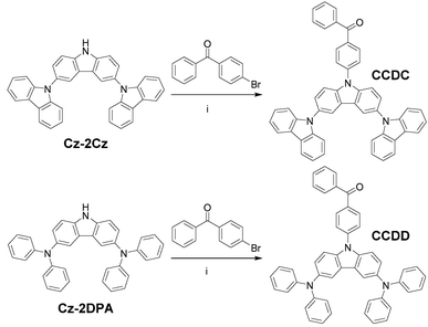
Herein, we introduce two materials named (4-(9′H-[9,3′:6′,9′′-tercarbazol]-9′-yl)phenyl)(phenyl)methanone (CCDC), and (4-(3,6-bis(diphenylamino)-9H-carbazol-9-yl)phenyl)(phenyl)methanone (CCDD) (Scheme 1). Benzophenone is a stable acceptor unit and both the carbazole and diphenylamine (DPA) are commonly used as stable donor units. Branch-shaped donors, where a carbazole unit is linked with two carbazoles or diphenylamines, are applied to increase the spatial volume of the HOMO and to enhance the electron donating ability of the donors.
Experimental section
General
1H and 13C NMR spectra were obtained with a Bruker NMR spectrometer operating at 600 and 150 MHz, respectively, in deuterated chloroform (CDCl3) solution at room temperature. Differential scanning calorimetry (DSC) measurements were performed on a Netzsch DSC 209 under a N2 flow at a heating and cooling rate of 10 °C min−1. Thermogravimetric analyses (TGA) were performed on a Netzsch TG 209 under a N2 flow at a heating rate of 10 °C min−1. UV-vis absorption spectra were recorded on a HP 8453 spectrophotometer. Photoluminescence (PL) spectra were measured using a Jobin-Yvon spectrofluorometer. Cyclic voltammetry (CV) was performed on a CHI600D electrochemical workstation with a Pt working electrode and a Pt wire counter electrode at a scanning rate of 100 mV s−1 against a Ag/Ag+ (0.1 M of AgNO3 in acetonitrile) reference electrode with a nitrogen-saturated anhydrous acetonitrile and dichloromethane (DCM) solution of 0.1 mol L−1 tetrabutylammonium hexafluorophosphate.The PL quantum yields (PLQYs) of the solution and film were measured using an integrating sphere on a HAMAMATSU absolute PL quantum yield spectrometer C11347. Transient PL decay was measured with an Edinburgh FL920 fluorescence spectrophotometer. The thin solid films used for absorption and PL spectral measurements were vacuum vapor deposited on quartz substrates. MALDI-TOF (matrix-assisted laser-desorption/ionization time-of-flight) mass spectra were obtained with a Bruker BIFLEXIII TOF mass spectrometer.
Theoretical calculation
Density functional theory (DFT) calculations were conducted using the Gaussian suite of programs (Gaussian 09-B01 package). The ground-state geometries of CCDC and CCDD were optimized using the B3LYP/6-31G(d) basis set in the gas phase.13 The minima were confirmed with all real frequencies. The excited singlet energy (ES), excited triplet energy (ET) and geometries of the excited states were calculated using peb1peb/6-31G(d) as the basis set.Materials
All solvents and raw materials were received from commercial suppliers and were used without further purification. 9′H-9,3′:6′,9′′-tercarbazole (Cz-2Cz) and N3,N3,N6,N6-tetraphenyl-9H-carbazole-3,6-diamine (Cz-2DPA) were synthesized according to the literature.14,15 The synthetic routes for CCDC and CCDD are outlined in Scheme 1. All of the developed materials were further purified by repeated temperature gradient vacuum sublimation.Device fabrication and measurements
Glass substrates pre-coated with a 95 nm thin layer of indium tin oxide (ITO) with a sheet resistance of 15–20 Ω sq−1 were thoroughly cleaned by ultrasonication with various detergents and treated with O2 plasma. The OLED devices were fabricated onto the cleaned ITO-coated glass substrates by thermal evaporation under high vacuum (∼5 × 10⁻⁴ Pa). The deposition rates were 0.5–2 Å s−1 for organic materials, 0.1 Å s−1 for the LiF layer, and 5–6 Å s−1 for the Al film. Current density–luminance–voltage (J–V–L) characteristics were measured using a Keithley 2400 and Konica Minolta CS-200 electroluminescence (EL) measurement system. EL spectra of the devices were recorded using a PR705 spectrometer and a Keithley 2400 power supply.Results and discussion
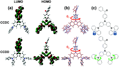
The thermal stabilities of CCDC and CCDD were investigated with respect to their glass transition temperature (Tg) and decomposition temperature (Td) (Fig. S1 in the ESI†). The temperatures at a 5% weight loss (Td) are 423 and 400 °C respectively for CCDC and CCDD. The Tg values of CCDC and CCDD are 157 and 123 °C, respectively. CCDC is slightly more thermally stable than CCDD due to it being more rigid and having better conjugation of carbazoles in comparison to DPA. The relatively high Tg and Td provide the materials with foreseeable stability in devices, which is critical for long device lifetimes.DFT calculations were employed to gain a deeper insight into the structure–property relationships of CCDC and CCDD (Fig. 1). The LUMOs of both compounds are located on the electron-withdrawing benzophenone moiety, and the HOMOs are dispersed over the electron-donating units; Cz-2Cz for CCDC and Cz-2DPA for CCDD. The dihedral angles between the donor and acceptor moieties are 53.0° for CCDC and 50.6° for CCDD. On the one hand, the moderately twisted configurations keep a controlled conjugation distance and prevent severe intermolecular π–π stacking induced by distorted planar geometries, and basically separate the HOMOs and LUMOs due to the ideal dihedral angles between the donor and acceptor moieties. On the other hand, not adapting the vertical dihedral angles enables a slight HOMO and LUMO overlap for efficient light emission.12 Due to the moderate dihedral angles between the electron donor and acceptor units and a slight overlap of the HOMOs and LUMOs, CCDC and CCDD show relatively high oscillator strengths of 0.1112 and 0.1550, respectively, indicating a highly facilitated radiative decay procedure. The ΔEST of CCDC was calculated to be 0.2970 eV, and it is slightly smaller for CCDD with a value of 0.1821 eV, which is attributed to the better HOMO–LUMO separation caused by DPA, a stronger electron donor than carbazole.
Calculations of molecular geometries at the excited states of CCDC and CCDD were performed to compare with their ground-state geometries (Fig. 1(b)). Major geometry changes take place between the benzophenone unit and the donor unit. The dihedral angle between the donor and the acceptor changes from 53.0° to 88.2° for CCDC and changes from 50.6° to 88.8° for CCDD. This is induced by the ICT process during the excitation of the molecules. The geometries of the Cz-2Cz unit of CCDC and the Cz-2DPA unit of CCDD basically remain unchanged, indicating the geometric stability of those two donor units. Such stable geometries in the excitation process are crucial for controlling the energy loss and ensuring the quantum yield of a material.10
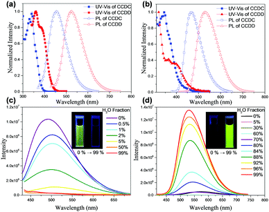
The steady state UV-vis absorption and PL spectra of both materials were recorded (Fig. 2(a) and (b)). The absorption band at 354 nm of CCDC and the peak at 380 nm of CCDD in toluene may be attributed to the internal charge transfer from the donors to the benzophenone acceptor unit, which implies the existence of an ICT effect for those two molecules. The sharp peak at 342 nm of CCDC and the one at 360 nm of CCDD are the absorption bands of the π–π* transition of the molecular backbones. The sharp peak at 329 nm may be attributed to the π–π* transition of the tricarbazole unit in CCDC. The traits of the film absorption spectra bear resemblance to those of the solutions, except for the slight red-shift caused by aggregation. The maximum emission of CCDC in toluene is at 456 nm and that of CCDD is at 526 nm. Besides, whether in toluene solution or in neat film, each material shows a structureless single-peak emission band, which indicates that both CCDC and CCDD are charge transfer (CT) emitters. The PL spectra are red-shifted by 12 nm to 468 nm for CCDC and by 5 nm to 531 nm for CCDD in neat films. To investigate their S1, T1 and ΔEST, fluorescence and phosphorescence spectra of CCDC and CCDD were obtained in toluene at 77 K (Fig. S2 in the ESI†). S1 and T1 are estimated from the peak values of the fluorescence and phosphorescence spectra, respectively, and the results are shown in Table 1. The ΔEST of CCDC is 0.147 eV and that of CCDD is 0.045 eV and basically coincide with the calculation results. So, despite the slight overlap of the HOMOs and LUMOs according to the aforementioned calculations, a low ΔEST can still be promised to achieve TADF properties. Thus, both efficient RISC and radiative decay can be facilitated, which would eventually improve their quantum efficiency.
| Compounds | T d/Tg (°C) | HOMO/LUMOa (eV) | Theoreticalb (eV) | Experimentalc (eV) | ||||
|---|---|---|---|---|---|---|---|---|
| S1 | T1 | ΔEST | S1 | T1 | ΔEST | |||
a Estimated from the empirical formulae: EHOMO = −(Eox + 4.323) eV, ELUMO = 1240/λabs![[thin space (1/6-em)]](https://www.rsc.org/images/entities/char_2009.gif) onset + EHOMO.
b Theoretical values of S1, T1, and ΔEST were simulated by peb1peb/6-31G*.
c Measured values of S1, T1, and ΔEST were estimated from the fluorescence and phosphorescence spectra of the investigated organics in toluene solution at 77 K. onset + EHOMO.
b Theoretical values of S1, T1, and ΔEST were simulated by peb1peb/6-31G*.
c Measured values of S1, T1, and ΔEST were estimated from the fluorescence and phosphorescence spectra of the investigated organics in toluene solution at 77 K.
|
||||||||
| CCDC | 423/155 | −5.178/−2.240 | 3.099 | 2.802 | 0.297 | 2.825 | 2.678 | 0.147 |
| CCDD | 400/121 | −5.065/−2.319 | 2.699 | 2.517 | 0.182 | 2.680 | 2.635 | 0.045 |
It is worth noting that despite the similar structures of CCDC and CCDD, we observed that they have diverse photophysical properties. We recorded their PL spectra in THF/H2O mixed solvent with various THF/H2O proportions, and it was found that the PL intensity of CCDC is highest in pure THF, but drops drastically when the water ratio rises slightly. The PL intensity of the solution can barely be detected with a water ratio of over 5 vol%, which is a typical phenomenon for aggregation caused quenching (ACQ) (Fig. 2(c)). A slight bathochromic shift was found for the PL spectra of CCDC with an increasing proportion of water. In contrast, CCDD shows a very weak orange emission in pure THF solvent, and the emission becomes much stronger and is slightly blue shifted with a high water ratio. The PLQY of CCDD increases from lower than 1% in pure THF solvent to 29.4% in a mixed solvent of THF/H2O = 1![[thin space (1/6-em)]](https://www.rsc.org/images/entities/char_2009.gif) :
:![[thin space (1/6-em)]](https://www.rsc.org/images/entities/char_2009.gif) 99 (v/v), displaying traits of aggregation induced emission (AIE) (Fig. 2(d)). A similar phenomenon was also observed in some previously reported DPA-containing boron dipyrromethene (BODIPY) derivatives,16 which was explained by the twisted intramolecular charge transfer (TICT) mechanism, where D–A molecules experience a conformation change to a less planar conformation in high-polarity solvents by increasing the dihedral angles between the donor and acceptor units, through which the materials shift from sharp local excited (LE) emission to significantly weakened and red-shifted TICT emission. However, the distinctive phenomena of CCDC and CCDD do not exactly fit this mechanism. The donor–acceptor linkages of CCDC and CCDD are identical, but only CCDD shows such a phenomenon. From the Gaussian calculations of the ground-state and excited-state given above, both CCDC and CCDD experience similar and minor geometry change during excitation, so the discrepancy might not be explained by geometry change induced by excitation. In addition, CCDC and CCDD share a similar molecular structure and molecular weight, and the structural difference is merely on the exterior of the donor units, where two diphenylamines in CCDD are replaced by two carbazoles in CCDC. Compared to diphenylamine, the phenyl rings on the carbazole are interlocked so they are coplanar and better conjugated, whilst for diphenylamine, the phenyl rings are not coplanar due to steric hindrance, and they are more flexible in terms of the vibration and rotation of the single bond linking to the nitrogen atom. So, the geometric stability of CCDD would be worse than that of CCDC. Therefore, we supposed that in good solvents, the vibration and rotation of the phenyl rings on DPA may cost energy and cause non-radiative decay, lowering the PL quantum efficiency. However, in a mixed THF/H2O solvent with a high H2O ratio, the motion of the phenyl rings in the donor units of CCDD would be constrained due to molecular aggregation, and thus its configuration would be more stable and non-radiative decay would be controlled. Such restriction of intramolecular motion happens in some AIE molecules, leading to stronger PL emission in high water ratio solutions,17 and the emission behavior of CCDD in high water ratio solutions would be closer to that in the solid state. This can also explain the slight blue-shift of the emission spectra with an increasing proportion of water. The emission of CCDD red-shifts in high polarity solvent THF, but as the water proportion goes up, the influence of the solvent on CCDD diminishes.
99 (v/v), displaying traits of aggregation induced emission (AIE) (Fig. 2(d)). A similar phenomenon was also observed in some previously reported DPA-containing boron dipyrromethene (BODIPY) derivatives,16 which was explained by the twisted intramolecular charge transfer (TICT) mechanism, where D–A molecules experience a conformation change to a less planar conformation in high-polarity solvents by increasing the dihedral angles between the donor and acceptor units, through which the materials shift from sharp local excited (LE) emission to significantly weakened and red-shifted TICT emission. However, the distinctive phenomena of CCDC and CCDD do not exactly fit this mechanism. The donor–acceptor linkages of CCDC and CCDD are identical, but only CCDD shows such a phenomenon. From the Gaussian calculations of the ground-state and excited-state given above, both CCDC and CCDD experience similar and minor geometry change during excitation, so the discrepancy might not be explained by geometry change induced by excitation. In addition, CCDC and CCDD share a similar molecular structure and molecular weight, and the structural difference is merely on the exterior of the donor units, where two diphenylamines in CCDD are replaced by two carbazoles in CCDC. Compared to diphenylamine, the phenyl rings on the carbazole are interlocked so they are coplanar and better conjugated, whilst for diphenylamine, the phenyl rings are not coplanar due to steric hindrance, and they are more flexible in terms of the vibration and rotation of the single bond linking to the nitrogen atom. So, the geometric stability of CCDD would be worse than that of CCDC. Therefore, we supposed that in good solvents, the vibration and rotation of the phenyl rings on DPA may cost energy and cause non-radiative decay, lowering the PL quantum efficiency. However, in a mixed THF/H2O solvent with a high H2O ratio, the motion of the phenyl rings in the donor units of CCDD would be constrained due to molecular aggregation, and thus its configuration would be more stable and non-radiative decay would be controlled. Such restriction of intramolecular motion happens in some AIE molecules, leading to stronger PL emission in high water ratio solutions,17 and the emission behavior of CCDD in high water ratio solutions would be closer to that in the solid state. This can also explain the slight blue-shift of the emission spectra with an increasing proportion of water. The emission of CCDD red-shifts in high polarity solvent THF, but as the water proportion goes up, the influence of the solvent on CCDD diminishes.
Cyclic voltammetry was applied to test the electrochemical properties of CCDC and CCDD and estimate their HOMO levels (Fig. S3 in the ESI†). Their optical band gaps are determined by the on-set wavelengths of the UV-vis absorption spectra in the thin solid film state, and the LUMO levels are calculated by adding the HOMO levels to the optical band gaps. The HOMO and LUMO energy levels are estimated to be −5.178 and −2.240 eV for CCDC and −5.065 and −2.319 eV for CCDD, respectively. The optical band gap of CCDD is 0.192 eV narrower than that of CCDC due to the stronger electron-donating ability of DPA over carbazole. The HOMO levels of both compounds are relatively shallow because of the collaborative electron-donating effect of the three donor units, which may assist in hole trapping in electroluminescent devices.
To further investigate the performance of CCDC and CCDD in the solid state, the PLQYs of CCDC and CCDD in neat films and doped films were examined. The PLQYs of the neat films of CCDC and CCDD were 19.6% and 30.8%, respectively. The PLQYs of the co-deposited films of 15 wt% CCDC doped in bis((2-diphenylphosphino)phenyl)ether oxide (DPEPO) and 15 wt% CCDD doped in 4,4′-di(9H-carbazol-9-yl)-1,1′-biphenyl (CBP) increased to 73.9% and 79.1%, respectively. It can be noticed that, despite the AIE phenomenon displayed in the THF/H2O solution, the PLQY of the doped film of CCDD still shows an evident increase compared to that of its neat film. So, ACQ exists for both CCDC and CCDD in a thin solid film. As has been mentioned before, it could be assumed that the increasing configuration stability acts as the major contributor to the enhanced PL intensity of CCDD in the solvent as the H2O proportion goes up. The PLQY tests further support the assumption that the enhancement of the PL intensity of CCDD can be attributed to the confinement of the vibration and rotation of the phenyl rings in CCDD during their aggregation in bad solvents. However, whether in doped films or neat films, such configuration changes are highly confined since the molecules are in the solid state. So, the PL emission is effective in doped films owing to the reduced configuration instability, which is a single-molecule behavior. But ACQ can still happen for CCDD in neat films because aggregation among molecules is a multi-molecule behavior that is different from the single-molecule behavior of the configuration change, and, in this case, such aggregation hampers the PL emission of CCDD when it prevails.
In order to study their device performance, several devices were designed and fabricated with the developed materials as the emitter. A vacuum-deposited blue-emitting device was fabricated for CCDC with a structure of ITO (95 nm)/1,1-bis[4-[N,N-di(p-tolyl)-amino]phenyl]cyclohexane (TAPC) (35 nm)/1,3-di(9H-carbazol-9-yl)benzene (mCP) (10 nm)/emission layer (EML) (25 nm)/1,3,5-tri(m-pyrid-3-yl-phenyl)benzene (TmPyPB) (40 nm)/LiF (0.8 nm)/Al (100 nm), where the EML is a co-deposited layer of CCDC (15 wt%)![[thin space (1/6-em)]](https://www.rsc.org/images/entities/char_2009.gif) :
:![[thin space (1/6-em)]](https://www.rsc.org/images/entities/char_2009.gif) DPEPO. A non-doped device with CCDC as the emitter was also fabricated with the same structure (Fig. 3(a) and Fig. S4(a) in the ESI†). TAPC and TmPyPB were used as the hole-transporting layer (HTL) and the electron-transporting layer (ETL), respectively, and mCP inserted between TAPC and the EML acts as an electron and exciton blocking layer. mCP has a high T1 value (2.9 eV) which is conducive to confining excitons to the EML and reducing efficiency roll-off.18 As for CCDD, a green-emitting device structure was fabricated as: ITO (95 nm)/TAPC (25 nm)/EML (35 mm)/TmPyPB (55 nm)/LiF (0.8 nm)/Al (100 nm), where the EML is a co-deposited layer of CCDD (15 or 30 wt%)
DPEPO. A non-doped device with CCDC as the emitter was also fabricated with the same structure (Fig. 3(a) and Fig. S4(a) in the ESI†). TAPC and TmPyPB were used as the hole-transporting layer (HTL) and the electron-transporting layer (ETL), respectively, and mCP inserted between TAPC and the EML acts as an electron and exciton blocking layer. mCP has a high T1 value (2.9 eV) which is conducive to confining excitons to the EML and reducing efficiency roll-off.18 As for CCDD, a green-emitting device structure was fabricated as: ITO (95 nm)/TAPC (25 nm)/EML (35 mm)/TmPyPB (55 nm)/LiF (0.8 nm)/Al (100 nm), where the EML is a co-deposited layer of CCDD (15 or 30 wt%)![[thin space (1/6-em)]](https://www.rsc.org/images/entities/char_2009.gif) :
:![[thin space (1/6-em)]](https://www.rsc.org/images/entities/char_2009.gif) CBP, and a non-doped device with CCDD as the emitter with the same structure was also fabricated (Fig. 3(b) and Fig. S4(b) in the ESI†).
CBP, and a non-doped device with CCDD as the emitter with the same structure was also fabricated (Fig. 3(b) and Fig. S4(b) in the ESI†).
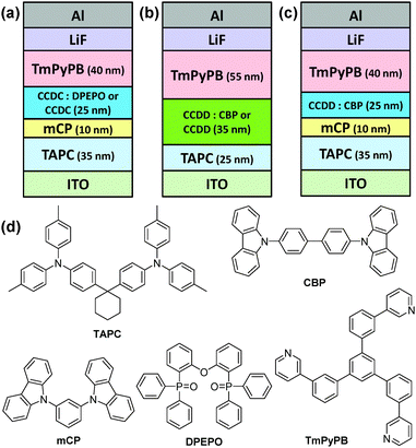 | ||
| Fig. 3 Structures of the devices containing (a) CCDC and (b and c) CCDD as the emitter and (d) the chemical structures of the materials used. | ||
The doped device of CCDC reaches a maximal EQE of 15.9% (Fig. S5 and Table S1 in the ESI†), which is by far the highest EQE ever reported for blue emitters based on the benzophenone acceptor moiety.19,20 However, in the non-doped device, the maximal EQE significantly diminishes to approximately 2%, which can be explained by the severe ACQ effect of the material.
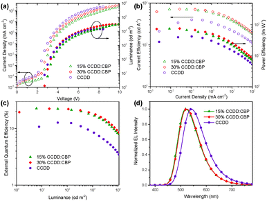
The devices based on CCDD with doping concentrations of 15 and 30 wt% were fabricated to investigate the influence of dopant concentration on device performance. The device properties are demonstrated in Fig. 4 and summarized in Table 2. Lower doping concentrations of 3 and 6 wt% were also tried out (Fig. S6 in the ESI†), and it turned out that the devices with high doping concentrations outperform those with low concentrations from an overall perspective. With a 15 wt% doping concentration, a maximal EQE is achieved at 22.6%, and with a 30 wt% doping concentration, the maximal EQE still remains 22.4%. Besides, the on-set voltages of these two devices are impressively low at 2.7 and 2.6 V, giving maximal power efficiencies of 74.0 and 74.8 lm W−1, respectively, which indicates that carrier injection and transport are effective in these devices due to direct carrier trapping by the CCDD dopant. This can also be reflected by a reduced driving voltage with an improvement in the doping concentration. Moreover, the CCDD-based devices display low efficiency roll-off. At a luminance of 1000 cd m−2, the EQE still remains as high as 17.3% and 18.6% for the concentrations of 15 and 30 wt%, respectively, which can sufficiently meet the demand for illumination. This is also one of the best-performing green emitting TADF materials regarding its overall properties.
| EML | V ON (V) | Max. efficiency | EQE1000 (%) | L max (cd m−2) | CIE (x, y) (@ 1 mA cm2) | ||
|---|---|---|---|---|---|---|---|
| CEmax (cd A−1) | PEmax (lm W−1) | EQEmax (%) | |||||
| a V ON and EQE1000 are obtained at a luminance of 1 and 1000 cd m−2, respectively. | |||||||
| 3 wt% CCDD:CBP | 5.4 | 55.7 | 48.6 | 19.0 | 10.7 | 24![[thin space (1/6-em)]](https://www.rsc.org/images/entities/char_2009.gif) 200 200 |
(0.288, 0.542) |
| 6 wt% CCDD:CBP | 5.1 | 64.1 | 61.0 | 21.2 | 12.8 | 26![[thin space (1/6-em)]](https://www.rsc.org/images/entities/char_2009.gif) 100 100 |
(0.297, 0.548) |
| 15 wt% CCDD:CBP | 2.7 | 70.7 | 74.0 | 22.6 | 17.3 | 31![[thin space (1/6-em)]](https://www.rsc.org/images/entities/char_2009.gif) 400 400 |
(0.309, 0.554) |
| 30 wt% CCDD:CBP | 2.6 | 71.4 | 74.8 | 22.4 | 18.6 | 31![[thin space (1/6-em)]](https://www.rsc.org/images/entities/char_2009.gif) 800 800 |
(0.329, 0.564) |
| CCDD | 2.4 | 39.8 | 41.7 | 12.7 | 8.76 | 14![[thin space (1/6-em)]](https://www.rsc.org/images/entities/char_2009.gif) 600 600 |
(0.388, 0.560) |
The electroluminescence of the non-doped device of CCDD experiences a bathochromic shift from 520 nm in the doped devices with concentrations of 15 and 30 wt% to yellow emission at 543 nm due to intermolecular aggregation. The on-set voltage drops even lower to 2.4 V for the non-doped device, which is comparable to that of p–n heterojunction devices with TADF emitters with the lowest on-set voltage that has ever been reported (2.35 V),21 further indicating that CCDD is a direct contributor to the reduction of on-set voltages due to direct carrier trapping. In contrast, the maximal EQE of the non-doped device is merely 12.7% because of the lower PLQY of the non-doped film, which is approximately half that of the doped devices. The efficiency roll-off is also relatively severe with an EQE of 8.5% left at a luminance of 1000 cd m−2. The efficiency drop indicates that the assistance of CBP as a host material is crucial for improving the electroluminescence in these devices. We further verify that, as is the same for the CCDC-based devices, aggregation induced quenching also exists among CCDD molecules, which can be reflected by the bathochromic shift compared to the doped films, and such aggregation hampers luminescence, lowering the EQE and exacerbating the efficiency roll-off. But when the CCDD molecules are dispersed in CBP, the intermolecular stacking is weakened while maintaining ideal conformation stability, and the device properties are improved.
To further optimize the efficiency roll-off of the devices, a layer of mCP (10 nm) was inserted between the EML and TAPC (Fig. 3(c) and Fig. S4(c) in the ESI†). Doping concentrations of 15 and 30 wt% of CCDD were applied to investigate the influence of the mCP layer on the performance of the devices. The electroluminescence properties of the devices are listed in Table 3. Compared to the mCP-free devices, the maximal EQE of the mCP layer inserted device with a 15 wt% concentration rises to 22.7% but that of a 30 wt% concentration device falls slightly to 21.3%. Nevertheless, further reduced efficiency roll-off can be observed for both devices. The EQEs still remain very high at 18.6% and 19.0% at a luminance of 1000 cd m−2 for the devices with 15 and 30 wt% concentrations. This may be attributed to the high T1 (2.9 eV) of mCP and more balanced carrier transportation. But the drawback is the sacrifice of the driving voltage due to the reduced carrier transport to the EML, leading to the decrease in power efficiency (Fig. S7 in the ESI†). Moreover, the devices doped with 30 wt% CCDD show lower efficiency roll-off regardless of having the mCP layer or not, compared to the devices with a 15 wt% doping concentration. It may be attributed to the carrier trapping effect of CCDD, owing to its shallow HOMO level, and the low ΔEST of CCDD contributes to the fast RISC procedure of the T1 excitons. However, in non-doped devices where the concentration of CCDD increases to 100%, CCDD molecules experience severe stacking and ACQ occurs among CCDD molecules, which worsens device performance.
| EML | V ON (V) | Max. efficiency | EQE1000 (%) | L max (cd m−2) | CIE (x, y) (@ 1 mA cm2) | ||
|---|---|---|---|---|---|---|---|
| CEmax (cd A−1) | PEmax (lm W−1) | EQEmax (%) | |||||
| a V ON and EQE1000 were obtained at a luminance of 1 and 1000 cd m−2, respectively. | |||||||
| 15 wt% CCDD:CBP | 3.3 | 72.1 | 61.5 | 22.7 | 18.6 | 42![[thin space (1/6-em)]](https://www.rsc.org/images/entities/char_2009.gif) 700 700 |
(0.315, 0.560) |
| 30 wt% CCDD:CBP | 3.1 | 68.2 | 61.0 | 21.3 | 19.0 | 42![[thin space (1/6-em)]](https://www.rsc.org/images/entities/char_2009.gif) 500 500 |
(0.336, 0.567) |
In order to demonstrate the TADF characteristics of these emitters, time-resolved transient PL decay spectra were measured for the doped films of CCDC and CCDD (Fig. 5). For the film where CCDC is doped in DPEPO, the transient decay lifetime for the prompt component is 17 ns at 300 K, and the delayed component has a decay lifetime of 12.6 μs. For the doped film of CCDD![[thin space (1/6-em)]](https://www.rsc.org/images/entities/char_2009.gif) :
:![[thin space (1/6-em)]](https://www.rsc.org/images/entities/char_2009.gif) CBP at 300 K, the prompt component has a decay lifetime of 16 ns and the decay lifetime for the delayed component is 10.2 μs. The decay lifetimes of both films are relatively short, in microsecond scale, which can be attributed to their low ΔEST. The excitons on T1 are highly inclined to transfer to S1 through a RISC process, shortening the delayed decay lifetime. We also looked into the changes in delayed lifetime at different temperatures for both of the doped films. It was observed that the delayed decay component diminishes as the temperature falls. This is because the RISC from T1 to S1 requires energy from the environment to conquer the energy barrier between these two energy levels, so, when the temperature drops, less energy is provided from the environment, making it harder for the T1 excitons to transfer to S1. At 77 K, the delayed component can hardly be observed, and most of the triplet excitons return directly to S0 through non-radiative decay.
CBP at 300 K, the prompt component has a decay lifetime of 16 ns and the decay lifetime for the delayed component is 10.2 μs. The decay lifetimes of both films are relatively short, in microsecond scale, which can be attributed to their low ΔEST. The excitons on T1 are highly inclined to transfer to S1 through a RISC process, shortening the delayed decay lifetime. We also looked into the changes in delayed lifetime at different temperatures for both of the doped films. It was observed that the delayed decay component diminishes as the temperature falls. This is because the RISC from T1 to S1 requires energy from the environment to conquer the energy barrier between these two energy levels, so, when the temperature drops, less energy is provided from the environment, making it harder for the T1 excitons to transfer to S1. At 77 K, the delayed component can hardly be observed, and most of the triplet excitons return directly to S0 through non-radiative decay.
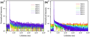 | ||
| Fig. 5 The transient photoluminescence decay of the (a) CCDC and (b) CCDD doped films (CCDC doped into DPEPO, 15 wt%; CCDD doped into CBP, 15 wt%). | ||
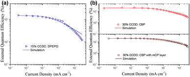
Due to the long lifetime of the triplet excitons, triplet–triplet annihilation (TTA) is a major factor which causes efficiency roll-off. There are also some other causes for efficiency roll-off, like singlet–triplet annihilation (STA).17,22 To delve deeper into the cause of the efficiency roll-off of the CCDC and CCDD based devices, a TTA model was adopted (eqn (1)).
 | (1) |
Conclusions
In summary, two D–A structured efficient TADF materials CCDC and CCDD with branch-shaped donor units were synthesized and studied. CCDC and CCDD demonstrate opposing phenomena in THF/H2O mixed solvent despite their structural similarity. The PL intensity of CCDC drops drastically as the proportion of water increases, while the PL intensity of CCDD increases with an increasing water ratio. But the PLQYs of both CCDC and CCDD are higher in doped films and their doped devices perform better compared to their non-doped ones. This is because the PL intensity of CCDD enhances when intramolecular motion is restrained, while it still suffers from quenching induced by intermolecular aggregation in the thin solid film state. The devices with these two TADF materials as emitters display outstanding performances. A maximal EQE of 15.9% was achieved in the blue-emitting devices with CCDC as the emitter, which is the highest ever value among the reported benzophenone-based blue emitters. Furthermore, the green-emitting devices where CCDD was utilized as the emitter perform well regarding their overall properties. Not only do their maximal EQEs exceed 22%, but they also achieve on-set voltages of as low as 2.6 V with a 30 wt% doping concentration. Moreover, the efficiency roll-off of the CCDD-based devices is well controlled. Insertion of an mCP exciton blocking layer has been proven to be conducive to further reducing the efficiency roll-off. An EQE of nearly 20% is maintained at a luminance of 1000 cd m−2. The outstanding performance of CCDC and CCDD can be reflected by their short delayed lifetimes, which are 12.6 and 10.2 μs for the doped films of CCDC and CCDD, respectively.Acknowledgements
The authors greatly appreciate the financial support from the National Key R&D Program of China (2016YFB0401004), the National Natural Science Foundation of China (51625301, 51573059 and 91233116), the 973 Project (2015CB655003), and the Guangdong Provincial Department of Science and Technology (2016B090906003).References
- C. W. Tang and S. A. VanSlyke, Appl. Phys. Lett., 1987, 51, 913–915 CrossRef CAS.
- Y. G. Ma, H. Zhang, J. C. Shen and C. Che, Synth. Met., 1998, 94, 245–248 CrossRef CAS.
- B. W. D’Andrade and S. R. Forrest, Adv. Mater., 2004, 16, 1585–1595 CrossRef.
- T. C. Chao, Y. T. Lin, C. Y. Yang, T. S. Hung, H. C. Chou, C. C. Wu and K. T. Wong, Adv. Mater., 2005, 17, 992–996 CrossRef CAS.
- H. Li, A. S. Batsanov, K. C. Moss, H. L. Vaughan, F. B. Dias, K. T. Kamtekar, M. R. Bryce and A. P. Monkman, Chem. Commun., 2010, 46, 4812–4814 RSC.
- M. A. Baldo, S. R. Forrest and M. E. Thompson, in Organic Electroluminescence, ed. Z. H. Kafafi, CRC Press, Boca Raton, FL, USA, 2005 Search PubMed.
- H. Uoyama, K. Goushi, K. Shizu, H. Nomura and C. Adachi, Nature, 2012, 492, 234–238 CrossRef CAS PubMed.
- Q. Zhang, B. Li, S. Huang, H. Nomura, H. Tanaka and C. Adachi, Nat. Photonics, 2014, 8, 326–332 CrossRef CAS.
- G. Xie, X. Li, D. Chen, Z. Wang, X. Cai, D. Chen, Y. Li, K. Liu, Y. Cao and S.-J. Su, Adv. Mater., 2016, 28, 181–187 CrossRef CAS PubMed.
- X. Cai, X. Li, G. Xie, Z. He, K. Gao, K. Liu, D. Chen, Y. Cao and S.-J. Su, Chem. Sci., 2016, 7, 4264–4275 RSC.
- A. Endo, K. Sato, K. Yoshimura, T. Kai, A. Kawada, H. Miyazaki and C. Adachi, Appl. Phys. Lett., 2011, 98, 083302 CrossRef.
- S. Hirata, Y. Sakai, K. Masui, T. Kai, A. Kawada, H. Miyazaki and C. Adachi, Nat. Mater., 2015, 14, 330–336 CrossRef CAS PubMed.
- (a) A. Becke, J. Chem. Phys., 1993, 98, 5648 CrossRef CAS; (b) C. Lee, W. Yang and R. G. Parr, Phys. Rev. B: Condens. Matter Mater. Phys., 1998, 37, 785–789 CrossRef.
- K. Albrecht and K. Yamamoto, J. Am. Chem. Soc., 2009, 131, 2244–2251 CrossRef CAS PubMed.
- H. Kuwabara, T. Takahashi, K. Shizu and C. Adachi, Jpn. Kokai Tokkyo Koho, 2015, 2015193555 Search PubMed.
- R. Hu, E. Lager, A. Aguilar-Aguilar, J. Liu, J. W. Y. Lam, H. H. Y. Sung, I. D. Williams, Y. Zhong, K. S. Wong, E. Pena-Cabrara and B. Z. Tang, J. Phys. Chem. C, 2009, 113, 15845–15853 CAS.
- H. Nie, K. Hu, Y. Cai, Q. Peng, Z. Zhao, R. Hu, J. Chen, S.-J. Su, A. Qin and B. Z. Tang, Mater. Chem. Front., 2017, 1, 1125–1129 RSC.
- Z. Wang, Y. Li, X. Cai, D. Chen, G. Xie, K. Liu, Y.-C. Wu, C.-C. Lo, A. Lien, Y. Cao and S.-J. Su, ACS Appl. Mater. Interfaces, 2016, 8, 8627–8636 CAS.
- S. Y. Lee, T. Yasuma, Y. S. Yang, Q. Zhang and C. Adachi, Angew. Chem., 2014, 53, 6402–6406 CrossRef CAS PubMed.
- X. Cai, B. Gao, X. Li, Y. Cao and S.-J. Su, Adv. Funct. Mater., 2016, 26, 8042–8052 CrossRef CAS.
- D. Chen, G. Xie, X. Cai, M. Liu, Y. Cao and S.-J. Su, Adv. Mater., 2016, 28, 239–244 CrossRef CAS PubMed.
- C. Murawski, K. Leo and M. C. Gather, Adv. Mater., 2013, 25, 6801–6827 CrossRef CAS PubMed.
Footnote |
| † Electronic supplementary information (ESI) available: NMR and MALDI-TOF spectra, TGA and DSC thermograms, fluorescence and phosphorescence spectra, cyclic voltammograms, device characteristics, etc. See DOI: 10.1039/c7qm00195a |
| This journal is © the Partner Organisations 2017 |

