DOI:
10.1039/C6QM00119J
(Research Article)
Mater. Chem. Front., 2017,
1, 181-189
Significance of π-bridge contribution in pyrido[3,4-b]pyrazine featured D–A–π–A organic dyes for dye-sensitized solar cells†
Received
9th July 2016
, Accepted 30th August 2016
First published on 21st September 2016
Abstract
The 3,4-ethylenedioxythiophene (EDOT) π-bridge is one of the most commonly used building blocks for sensitizers in dye-sensitized solar cells (DSSCs). We investigated its influence on the molecular structure, the photophysical and electrochemical properties compared to a cyclopentadithiophene (CPDT) π-bridge in two pyrido[3,4-b]pyrazine featured D–A–π–A dyes SH3 (CPDT π-bridge) and SH4 (EDOT π-bridge). Surprisingly SH4 with EDOT as a π-bridge exhibited not only poor absorptivity but also inferior photovoltaic performance. On the contrary, SH3 achieved more than 5% power conversion efficiency under standard AM1.5G illumination at 100 mW cm−2 when employed in both solid state and liquid state DSSCs. Theoretical calculations suggested a significant twist in the molecular configuration between EDOT and carboxylic acid. We attributed it to the interaction between the O atom of EDOT and the H atom of alkene as well as the repulsion between the O atoms of EDOT and the carbonyl group of the carboxylic acid, which could retard the intramolecular charge transfer process. Consequently, this rotation in the molecule decreases the molar extinction coefficient and increases charge recombination. Electrochemical impedance spectroscopy results showed enhanced charge recombination in DSSC devices based on SH4, undermining the charge collection efficiency and the power conversion efficiency compared to SH3. Herein the detrimental effect of tilting the dye structure is isolated from the other characteristics of the dye, showing its importance as a general design strategy for new dyes.
1. Introduction
As representatives of third-generation photovoltaic technologies, dye-sensitized solar cells (DSSCs) are appealing to researchers all over the world.1 Design of the sensitizers is one of the hottest topics considering the important role of sensitizers in the photovoltaic performance of DSSCs.2 A recent breakthrough of power conversion efficiencies (PCEs) for dye-sensitized solar cells (DSSCs) based on organic sensitizers has encouraged researchers to further investigate the relationships between the molecular structures of organic sensitizers and their photovoltaic performance in DSSCs.3 The majority of organic sensitizers are designed with donor (D)–π bridge–acceptor (A) configuration, because the push and pull effect between electron-rich donor and electron-deficient acceptor anchor groups enhances the intramolecular charge transfer (ICT) process, resulting in effective photon-to-electron conversion.2 Recent investigation suggested that by inserting an additional electron-withdrawing unit as an auxiliary acceptor between the donor and π-bridges, the ICT process can be further accelerated, leading to increased absorptivity. Such modification of the molecular structure enhances PCEs.4 These kinds of dyes are recognized as D–A–π–A-type sensitizers. The conjugated π-bridge plays an important role being capable of tuning the optical and electrochemical properties of the dye.5 Cyclopentadithiophene (CPDT) and 3,4-ethylenedioxythiophene (EDOT) are two of the most commonly used π-bridge building blocks investigated in organic dyes.6 The most famous and successful example of CPDT as a π-bridge is Y123. The PCE of DSSCs sensitized by Y123 reached 10.3% with cobalt-based electrolyte in combination with a PEDOT-coated counter electrode.7 One of the advantages of applying CPDT as a spacer is that structural modifications can be easily carried out on the CPDT unit. Extending the length of alkyl chains on the CPDT unit from methyl to octyl, the photovoltaic performance of the corresponding DSSCs dramatically increased.8 Earlier, EDOT was largely used in different areas such as conducting polymers and electrochromic materials due to its highly π-conjugated and good co-planarity.9 Later it was introduced into sensitizers for dye-sensitized solar cells.10 Ko et al. found that the dye using EDOT as the π-bridge shows a broader spectral response than its analogue with thiophene, and obtains a much higher photovoltaic device performance.11 Wang et al. reached a PCE of 9.4% using a triphenylamine-based donor dye with CPDT–EDOT as the π-bridge in DSSCs.12
Our group studied the insertion of thiophene, EDOT and CPDT units as π-bridges between bulky donor and auxiliary acceptor moieties of dyes and their influence on the photophysical properties and performance. We found that the sensitizer with EDOT obtained the highest PCE of 8.4% achieving the optimal balance between the charge recombination rate and the dye regeneration rate.13 Based on our previous work, we designed and synthesized two novel D–A–π–A sensitizers, SH3 and SH4, using 2,3-diphenylpyrido[3,4-b]pyrazine as the auxiliary acceptor, CPDT and EDOT as the π-bridge, respectively. With the aim of applying these two dyes for solid-state dye-sensitized solar cells, a bulky indoline donor was chosen to inhibit fast charge recombination at the interface of TiO2/dye/HTM (hole transporting material). SH4 with EDOT as the π-bridge exhibited extremely poor photovoltaic performance compared to SH3. To understand the dye structural variation on the device performance, we took the support of theoretical calculations and interfacial kinetics studies. We found that this remarkable difference in the dye effectiveness is closely related to the formation of a dihedral angle between EDOT and carboxylic acid (Fig. 1).
 |
| | Fig. 1 The molecular structures of SH3 and SH4. | |
2. Results and discussion
2.1 Synthesis
The synthetic routes of SH3 and SH4 are depicted in Scheme S1 (ESI†). Stille coupling reactions of 5,8-dibromo-2.3-diphenylpyrido[3,4-b]pyrazine with tributyl(2,3-dihydrothieno[3,4-b][1,4]dioxin-5-yl)stannane and (4,4-bis(2-ethylhexyl)-4H-cyclopenta[2,1-b:3,4-b′]dithiophen-2-yl)tributyl-stannane afforded compounds 1a and 1b, respectively. The Vilsmeier–Haack reaction of compounds 1a and 1b with phosphorus oxychloride in the presence of N,N-dimethylformamide provided the intermediate products 2a and 2b, respectively. In the next step, Suzuki coupling reactions of compounds 2a and 2b with (4-(4-(2,2-bis(2′,4′-bis-(octyloxy)-[1,1′-biphenyl]-4-yl)vinyl)phenyl)-1,2,3,3a,4,8b-hexahydrocyclo-penta[b]indol-7-yl)boronic acid resulted in aldehydes 3a and 3b, respectively. Finally, the target products SH3 and SH4 were synthesized by Knoevenagel reaction of aldehydes 3a and 3b with cyanoacetic acid in the presence of acetic acid and ammonium acetate, respectively. All key intermediates and two final sensitizers were fully characterized by 1H NMR, 13C NMR and HRMS.
2.2 Optical and electrochemical properties
The absorption spectra of SH3 and SH4 in CH2Cl2 solvent and on TiO2 films are shown in Fig. 2. The parameters of their optical and electrochemical properties are tabulated in Table 1. The substitution of CPDT or EDOT moieties as the π-bridge does not influence the main absorption peak of these two dyes in CH2Cl2. However, the molar extinction coefficient drops from 5.65 × 10⁴ M−1 cm−1 for SH3 to 1.80 × 10⁴ M−1 cm−1 for SH4. Since the main absorption band relates to the intramolecular charge transfer (ICT) between the donor moiety and the acceptor unit of the sensitizer, the poor molar extinction coefficient of SH4 indicates an inefficient ICT process and limited light harvesting ability, which could jeopardize its photovoltaic performance in DSSCs. The absorption spectra of SH3 and SH4 dyes sensitized on TiO2 films display hypochromatic shifts compared to their absorption spectra in solutions, which could be caused by the deprotonation of the carboxylic acid and H-aggregation of the dyes.14
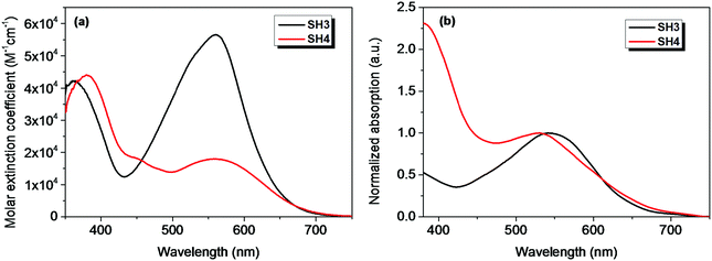 |
| | Fig. 2 The UV-Vis absorption spectra of SH3 and SH4 in CH2Cl2 (a) and on 4 μm TiO2 films (b). | |
Table 1 The optical and electrochemical properties of SH3 and SH4
| Dye |
λ
max
/nm (ε × 104 M−1 cm−1) |
λ
max
/nm |
HOMOc/V (vs. NHE) |
E
0–0
/eV |
LUMOe/V (vs. NHE) |
|
Absorption maximum in CH2Cl2 solution.
Absorption maximum on a 4 μm TiO2 film.
HOMO was measured in CH2Cl2 with 0.1 M tetra-n-butylammonium hexafluorophosphate (TBAPF6) as electrolyte (working electrode: Pt; counter electrode: Pt wire; reference electrode: SCE; calibrated with ferrocene/ferrocenium (Fc/Fc+, +0.69 V vs. NHE in CH2Cl2) as an external reference).
E
0–0 was estimated from the absorption onset wavelength from UV-Vis absorption spectra of the dyes.
LUMO was estimated by subtracting E0–0 from EHOMO.
|
|
SH3
|
562 (5.65) |
541 |
0.94 |
1.89 |
−0.95 |
|
SH4
|
561 (1.80) |
530 |
0.99 |
1.81 |
−0.82 |
To evaluate the electron injection and dye regeneration capability of SH3 and SH4, cyclic voltammograms (CV) were employed in CH2Cl2 solution, and CV plots are given in Fig. S1 (in the ESI†). The corresponding data are listed in Table 1. The HOMO energy levels of SH3 and SH4 are 0.94 and 0.99 V vs. NHE, respectively, which are higher than the redox potentials of I−/I3− (∼0.4 V vs. NHE), ensuring sufficient driving force for dye regeneration. The band-gap energies (E0–0) were estimated from the absorption thresholds of the dyes and the values are 1.89 and 1.81 for SH3 and SH4, respectively. By combining the HOMO energy levels with the energy of transition (E0–0), the LUMO energy levels of SH3 and SH4 are −0.95 and −0.82. With EDOT as the π-bridge, the LUMO energy level of SH4 shifted downwards by 130 mV, compared to that of SH3. However, considering the negative LUMO energy level of SH4 compared to the TiO2 conduction band edge energy level (−0.5 V vs. NHE) it is expected to be a good sensitizer with a sufficient driving force for the electron-injection process.
2.3 Theoretical calculations
To gain more clear insight into these two dyes, theoretical calculations were performed. Fig. 3 exhibits the molecular orbital distributions and energies of SH3 and SH4 in CH2Cl2 solvent (isodensity = 0.020 a.u.). We can see that the HOMO locates mainly on the indoline-based donor part and the LUMO locates mainly on the auxiliary acceptor, the π-bridge and acceptor parts for both SH3 and SH4. However, the HOMO of SH3 extends through the auxiliary acceptor to the CPDT unit. While for SH4, its HOMO barely reaches the EDOT unit and has much less portion on the auxiliary acceptor part. This could largely limit charge transfer from the bulky donor to the carboxylic acid acceptor. The calculated energies and compositions of selected transitions of SH3 and SH4via time-dependent density functional theory (TD-DFT) are listed in Table 2. For SH4, the much smaller oscillator strength value of the absorption at 559.30 nm suggests a much smaller possibility of absorption in these corresponding transitions, which agrees well with the experiment. This could be attributed to the smaller overlap of orbitals between the HOMO (HOMO−1) and the LUMO of SH4 compared to that of SH3.
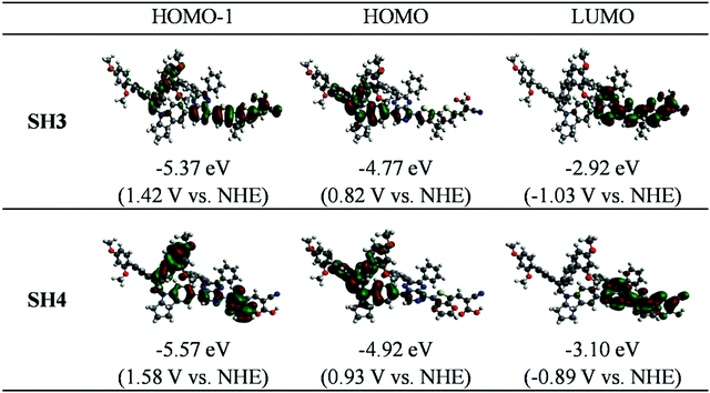 |
| | Fig. 3 Molecular orbital distributions and energies of SH3 and SH4 in CH2Cl2 (isodensity = 0.020 a.u.) | |
Table 2 TD-DFT calculated energies and compositions of selected transitions of SH3 and SH4
| Compounds |
E (nm) |
Compositions |
f
|
|
SH3
|
560.27 |
45% H → L, 43% H−1 → L |
2.34 |
| 347.80 |
69% H → L+3 |
0.52 |
|
|
|
SH4
|
559.30 |
53% H → L, 25% H−1 → L |
1.14 |
| 474.31 |
18% H → L, 13% H−1 → L |
0.21 |
The dihedral angles of optimized ground-state SH3 and SH4 under vacuum are listed in Table 3, where α, β and γ are the dihedral angles between the donor and the auxiliary acceptor, between the auxiliary acceptor and the π-bridge unit as well as between the π-bridge unit and the acceptor, respectively. We can see that the dihedral angles between the indoline donor and 2,3-diphenylpyrido[3,4-b]pyrazine are both over 40° for SH3 and SH4. This large twist has been proved to be beneficial for charge separation and charge flow directionality in the dye molecule.17 2,3-Diphenylpyrido[3,4-b]pyrazine shows good coplanarity with both CPDT and EDOT, enabling efficient charge transfer from the donor to the acceptor. However, SH4 exhibits a big dihedral angle of 31.6° between EDOT and carboxylic acid while the angle is only −0.1° for CPDT with carboxylic acid (CA) in SH3. Fig. 4 shows the molecular top and side views of SH3 and SH4 under vacuum. We ascribe this non-planarity to the repulsion between the O atoms of EDOT and the carbonyl group of the carboxylic acid, leading to the big configurational twist between EDOT and the CA units. This large twist would weaken the intramolecular charge transfer process responsible for the decrease of the molar extinction coefficient and the IPCE.
Table 3 Dihedral angles of optimized ground-state SH3 and SH4 under vacuum
| Compound |
α (°) |
β (°) |
γ (°) |
|
SH3
|
−41.8 |
2.9 |
−0.1 |
|
SH4
|
−43.4 |
1.4 |
31.6 |
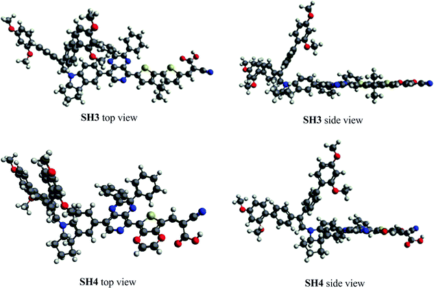 |
| | Fig. 4 The molecular top and side views of SH3 and SH4 under vacuum. | |
2.4 Photovoltaic performance of liquid-state DSSCs
The photovoltaic performance of devices with traditional iodine electrolyte was measured under three different light intensities (1 Sun, 0.5 Sun and 0.1 Sun) and their results are tabulated in Table 4. The PCE of SH3-based DSSCs were above 5.5% under different light intensities. The highest PCE of 5.74% was obtained under 0.5 Sun illumination with Voc = 0.690 V and Jsc = 5.41 mA cm−2. In the case of SH4, with EDOT as the π-bridge, the photovoltaic performance of the devices was much lower than that of their corresponding reference device of SH3. The DSSCs based on SH4 gave a PCE of 3.52% with Voc = 0.563 V and Jsc = 4.12 mA cm−2 under 0.5 Sun illumination. The IPCE spectra of liquid-state DSSCs based on SH3 and SH4 under illumination of 0.1 Sun are shown in Fig. 5. DSSCs based on SH3 with iodine electrolyte showed an IPCE over 55% in the wavelength range of 500−600 nm with a maximum of 62% at 550 nm while DSSCs based on SH4 showed an IPCE over 40% in the wavelength range of 510–610 nm with a maximum of only 45% at 540 nm under the same conditions, which are in accordance with their short current densities. The good linearity behavior and flat plateaus with different light intensities in the current dynamics plots of liquid-state DSSCs indicated good mass transportation in liquid electrolyte from 0.1 Sun to 1 Sun as shown in Fig. 6.
Table 4 The performance parameters of DSSCs based on SH3 and SH4 with iodide electrolyte under different light intensities (I0)
| Dye |
Dye loading (mol cm−2) |
I
0 (Sun) |
V
oc (V) |
J
sc (mA cm−2) |
FF |
PCE (%) |
|
SH3
|
1.05 × 10⁻⁷ |
1 |
0.705 |
10.42 |
0.741 |
5.54 |
| 0.5 |
0.690 |
5.41 |
0.773 |
5.74 |
| 0.1 |
0.645 |
1.03 |
0.815 |
5.69 |
|
|
|
SH4
|
1.13 × 10⁻⁷ |
1 |
0.579 |
7.71 |
0.756 |
3.43 |
| 0.5 |
0.563 |
4.12 |
0.768 |
3.52 |
| 0.1 |
0.520 |
0.82 |
0.776 |
3.47 |
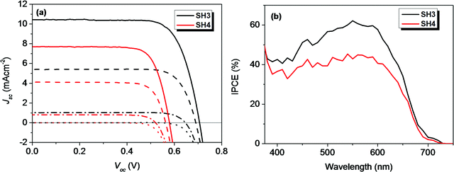 |
| | Fig. 5 (a) I–V curves and dark currents of DSSCs with iodide electrolyte based on SH3 and SH4 under different light intensities (solid, 1 Sun; dash, 0.5 Sun; dash dot, 0.1 Sun; dot, dark) and (b) IPCE plots under illumination of 0.1 Sun. | |
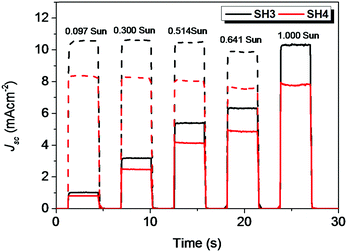 |
| | Fig. 6 Current dynamics plots of DSSCs based on SH3 and SH4 with iodide electrolyte (solid, experimental data; dash, current densities with illumination intensity converted to 1 Sun). | |
The IPCE spectrum can be expressed as IPCE = LHE × Φinj × ηc. The light-harvesting efficiency (LHE) is in direct proportion with the molar extinction coefficient. Φinj represents the electron injection efficiency. ηc corresponds to the electron collection efficiency. A time-resolved photoluminescence (TR-PL) decay measurement was conducted to calculate the electron injection efficiency according to ref. 15. The electron injection efficiency of SH3 and SH4 was calculated to be 75.5% and 61.8%, respectively (see Fig. S2, S3 and Table S1 in the ESI†). Therefore, the higher molar extinction coefficient, electron injection efficiency and electron collection efficiency (see electrochemical impedance spectroscopy) of SH3-based devices lead to the improvement of the IPCE, resulting in the higher Jsc than that of SH4-based DSSCs. Moreover, we checked the dye loadings of SH3 and SH4 with iodine electrolyte, which may be another influencing factor of photocurrent. Similar dye loadings indicated that it had no significant impact on the photocurrent.
2.5 Electrochemical impedance spectroscopy
To understand the electronic processes at interfaces in the devices, we performed electrochemical impedance spectroscopy (EIS) on DSSCs with iodide electrolyte since this technique is well established for liquid-state DSSCs. Fig. 7 shows dark current plots of DSSCs based on SH3 and SH4 against the applied potentials. The bigger dark currents in DSSCs based on SH4 at higher potentials indicate higher charge recombination at the interface of TiO2/dye/electrolyte, thus more current loss in the device, which can partly contribute to the lower Jsc and Voc of DSSCs. The EIS data were fitted using a transmission line model16 and the results of the charge transfer resistance (Rct), charge transport resistance (Rtrans) and chemical capacitance (Cchem) of DSSCs based on SH3 and SH4 are presented in Fig. 8. Strikingly, the Rct values of DSSCs based on SH3 are about 20 times higher than that of the SH4-sensitized devices at the same corrected potentials, suggesting that DSSCs based on SH4 undergo rapid charge recombination. The Rtrans values of DSSCs based on SH4 are very close to Rct, resulting in two competing kinetic processes at the photoanode and augmentation of electron loss. The larger chemical capacitance of TiO2 in DSSCs based on SH4 suggested a downward shift of the conduction band, reducing Voc.
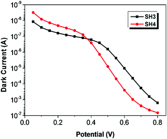 |
| | Fig. 7 Dark current plots of DSSCs based on SH3 and SH4 against the applied potentials. | |
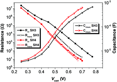 |
| | Fig. 8 Plots of charge transfer resistance (Rct), charge transport resistance (Rtrans) and chemical capacitance (Cchem) of DSSCs based on SH3 and SH4 extracted from the EIS measurement against potentials corrected with IR drop. | |
The electron lifetime (τct) and electron transport time (τtrans) of DSSCs based on SH3 and SH4 were calculated by applying equations of τct = Rct × Cchem and τtrans = Rtrans × Cchem17 and are shown in Fig. 9. The electron lifetime in DSSCs based on SH3 is much longer than that of SH4. The charge collection efficiency of SH4 is very low (60%) compared to SH3 based devices (90%) as shown in Fig. 10.
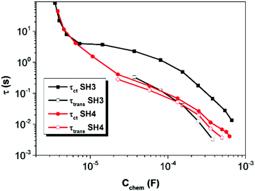 |
| | Fig. 9 Electron lifetime (τct) and electron transport time (τtrans) of DSSCs based on SH3 and SH4 calculated from the EIS measurement as a function of chemical capacitance. | |
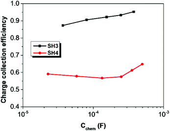 |
| | Fig. 10 Charge collection efficiency of DSSCs based on SH3 and SH4 as a function of chemical capacitance. | |
2.6 Photovoltaic performance of solid-state DSSCs
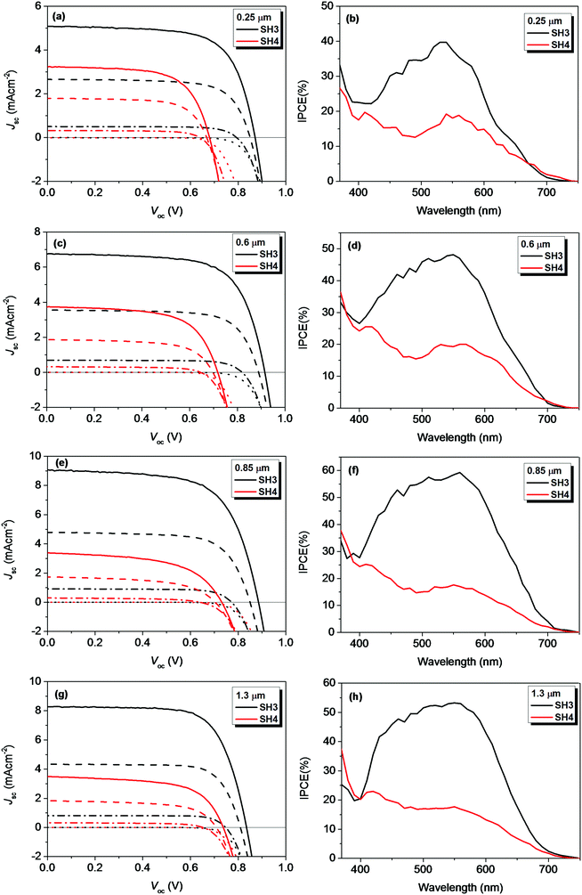
We further investigated the photovoltaic performance of solid-state DSSCs (ssDSSCs) based on SH3 and SH4 using Spiro-OMeTAD as a hole-transporting material (HTM). Fig. 11 exhibited the J–V curves and dark currents of ssDSSCs based on SH3 and SH4 with different film thicknesses of mesoporous TiO2 layers under different light intensities and their corresponding IPCE plots under illumination of 0.1 Sun. The photovoltaic parameters are listed in Tables 5 and 6. The increase of the TiO2 film thickness can have multiple effects on ssDSSCs. On the one hand, the increase of the TiO2 film thickness can improve the light harvesting ability of the device, generating more electrons. On the other hand, the thicker TiO2 film can also increase the diffusion length for photo-generated electrons, increasing the possibility of charge recombination during the electron transporting process in photoanodes. These two competing processes determine the effect on device performance with increased TiO2 film thickness. That is also the reason why there is an optimized TiO2 film thickness in both ssDSSCs and traditional DSSCs with liquid electrolytes. For SH3-senzitized ssDSSCs, the Jsc of the devices improved by increasing the film thickness up to 0.85 μm and above this level it dropped. The highest Jsc of 9.08 mA cm−2 was obtained with a 0.85 μm TiO2 film. Correspondingly, the IPCE of SH3-based devices was over 50% in the wavelength range of 460–590 nm with a maximum of 59% at 560 nm. Under 1 Sun illumination, the SH3-based devices showed a Voc of 835 mV, a Jsc of 8.28 mA cm−2 and the PCE of 5.07%. While for the ssDSSCs sensitized by SH4, the Jsc did not change with the film thickness, which was slightly above 3 mA cm−2. Considering the low molar extinction coefficient of SH4, lower light harvesting efficiency on the thin mesoporous TiO2 films was expected. However, IPCE plots of SH4-based ssDSSCs with different film thicknesses presented a similar IPCE plateau with a maximum of about only 20%. This indicates not only a considerable current loss in SH4-based ssDSSCs but also implies that lower electron injection efficiency and electron collection efficiency might be contributing to the poor IPCE values obtained with thicker TiO2 films. No helpful improvement was observed by adjusting the TiO2 film thickness. The highest PCE of only 1.69% was obtained by SH4-based ssDSSCs with 0.6 μm TiO2 films under 1 Sun illumination.
 |
| | Fig. 11
I–V curves and dark currents of ssDSSCs based on SH3 and SH4 with different film thickness of mesoporous TiO2 layers under different light intensities (solid, 1 Sun; dash, 0.5 Sun; dash dot, 0.1 Sun; dot, dark) and IPCE plots under illumination of 0.1 Sun. | |
Table 5 The performance parameters of ssDSSCs based on SH3 with different mesoporous TiO2 film thicknesses under different light intensities (I0)
| Film thickness (μm) |
I
0 (Sun) |
V
oc (V) |
J
sc (mA cm−2) |
FF |
PCE (%) |
| ∼0.25 |
1 |
0.871 |
5.07 |
0.686 |
3.13 |
| 0.5 |
0.850 |
2.66 |
0.710 |
3.21 |
| 0.1 |
0.794 |
0.51 |
0.746 |
3.21 |
|
|
| ∼0.60 |
1 |
0.915 |
6.75 |
0.684 |
4.25 |
| 0.5 |
0.889 |
3.54 |
0.718 |
4.42 |
| 0.1 |
0.820 |
0.69 |
0.755 |
4.46 |
|
|
| ∼0.85 |
1 |
0.885 |
9.08 |
0.651 |
5.29 |
| 0.5 |
0.850 |
4.79 |
0.697 |
5.56 |
| 0.1 |
0.772 |
0.92 |
0.745 |
5.52 |
|
|
| ∼1.30 |
1 |
0.835 |
8.28 |
0.701 |
5.07 |
| 0.5 |
0.809 |
4.33 |
0.743 |
5.32 |
| 0.1 |
0.747 |
0.81 |
0.792 |
5.20 |
Table 6 The performance parameters of ssDSSCs based on SH4 with different mesoporous TiO2 film thicknesses under different light intensities (I0)
| Film thickness (μm) |
I
0 (Sun) |
V
oc (V) |
J
sc (mA cm−2) |
FF |
PCE (%) |
| ∼0.25 |
1 |
0.680 |
3.24 |
0.651 |
1.48 |
| 0.5 |
0.668 |
1.79 |
0.681 |
1.63 |
| 0.1 |
0.640 |
0.32 |
0.691 |
1.53 |
|
|
| ∼0.60 |
1 |
0.717 |
3.73 |
0.629 |
1.69 |
| 0.5 |
0.697 |
1.87 |
0.639 |
1.62 |
| 0.1 |
0.646 |
0.32 |
0.639 |
1.37 |
|
|
| ∼0.85 |
1 |
0.731 |
3.39 |
0.554 |
1.39 |
| 0.5 |
0.704 |
1.74 |
0.558 |
1.34 |
| 0.1 |
0.640 |
0.29 |
0.547 |
1.08 |
|
|
| ∼1.30 |
1 |
0.737 |
3.49 |
0.616 |
1.66 |
| 0.5 |
0.709 |
1.84 |
0.623 |
1.65 |
| 0.1 |
0.653 |
0.33 |
0.629 |
1.45 |
The current dynamics plots of ssDSSCs based on SH3 and SH4 with different TiO2 film thicknesses are shown in Fig. 12. The flat plateau indicated that the charge extractions in ssDSSCs were effective under different light intensities.
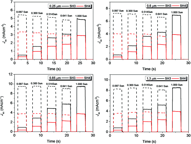 |
| | Fig. 12 Current dynamics plots of ssDSSCs based on SH3 and SH4 with different film thicknesses of mesoporous TiO2 layers (solid, experimental data; dash, current densities with illumination intensity converted to 1 Sun). | |
3. Conclusion
We designed and synthesized two D–A–π–A dyes with a bulky indoline donor, 2,3-diphenylpyrido[3,4-b]pyrazine as an auxiliary acceptor, CPDT (SH3) and EDOT (SH4) as π-bridges, and cyanocarboxylic acid as an acceptor. We compared the effect of the π-bridge on the optical and electrochemical properties, the molecular configuration and the photovoltaic performance in liquid and ss-DSSCs. The presence of a N atom in the pyridine ring of the 2,3-diphenylpyrido[3,4-b]pyrazine close to the π-bridge, EDOT, in SH4 caused not only a dramatic decrease in the molar extinction coefficient but also in the photovoltaic performance. Theoretical calculations revealed that molecular planarity plays a crucial role. The larger twist between EDOT and the carboxylic acid unit decreases remarkably the molar extinction coefficient and increases charge recombination. The reason for the unusual phenomenon might be related to the interaction between the O atom of EDOT and the H atom of alkene as well as the repulsion between the O atoms of EDOT and the carbonyl group of carboxylic acid, leading to a big configurational twist between the EDOT and CA units. EIS measurements confirmed the increased charge recombination rates in DSSC devices based on SH4, which resulted in poor charge collection efficiency, low Jsc and Voc, and thus lower PCE. Finally ssDSSCs sensitized with SH3 obtained 5.07% PCE, which is remarkable considering the extremely thin TiO2 layer of 1.3 μm under illumination of 1 Sun.
Acknowledgements
This work was supported by the Science Fund for Creative Research Groups (21421004), NSFC/China (21372082, 21572062, 2116110444, 21172073 and 91233207), and the Programme of Introducing Talents of Discipline to Universities (B16017). Zhang thanks China Scholarship Council (CSC) for the financial support of a visiting program at EPFL. MG acknowledges financial support from the Swiss National Science Foundation and CTI 17622.1 PFNM-NM, glass2energy SA (g2e), Villaz-St-Pierre, Switzerland.
References
- A. Hagfeldt, G. Boschloo, L. Sun, L. Kloo and H. Pettersson, Chem. Rev., 2010, 110, 6595 CrossRef CAS PubMed; N. Sharifi, F. Tajabadi and N. Taghavinia, ChemPhysChem, 2014, 15, 3902 CrossRef PubMed.
- A. Mishra, M. K. R. Fischer and P. Bäuerle, Angew. Chem., Int. Ed., 2009, 48, 2474 CrossRef CAS PubMed; Z. Ning, Y. Fu and H. Tian, Energy Environ. Sci., 2010, 3, 1170 Search PubMed; X. Zhang, M. Grätzel and J. Hua, Front. Optoelectron., 2016, 9, 3 CrossRef.
- K. Kakiage, Y. Aoyama, T. Yano, K. Oya, J. Fujisawa and M. Hanaya, Chem. Commun., 2015, 51, 15894 RSC; K. Kakiage, Y. Aoyama, T. Yano, K. Oya, T. Kyomen and M. Hanaya, Chem. Commun., 2015, 51, 6315 RSC; Z. Yao, M. Zhang, H. Wu, L. Yang, R. Li and P. Wang, J. Am. Chem. Soc., 2015, 137, 3799 CrossRef CAS PubMed.
- Y. Wu and W. Zhu, Chem. Soc. Rev., 2013, 42, 2039 RSC; Y. Wu, W. Zhu, S. M. Zakeeruddin and M. Grätzel, ACS Appl. Mater. Interfaces, 2015, 7, 9307 Search PubMed.
- K. D. Seo, I. T. Choi and H. K. Kim, Chem. – Eur. J., 2015, 21, 14804 CrossRef CAS PubMed; R. Grisorio, L. D. Marco, R. Agosta, R. Iacobellis, R. Giannuzzi, M. Manca, P. Mastrorilli, G. Gigli and G. P. Suranna, ChemSusChem, 2014, 7, 2659 CrossRef PubMed; X. Zhang, L. Chen, X. Li, J. Mao, W. Wu, H. Ågren and J. Hua, J. Mater. Chem. C, 2014, 2, 4063 RSC.
- L. E. Polander, A. Yella, J. Teuscher, R. Humphry-Baker, B. F. E. Curchod, N. A. Astani, P. Gao, J.-E. Moser, I. Tavernelli, U. Rothlisberger, M. Grätzel, M. K. Nazeeruddin and J. Frey, Chem. Mater., 2013, 25, 2642 CrossRef CAS; W. Zhang, Y. Wu, H. Zhu, Q. Chai, J. Liu, H. Li, X. Song and W.-H. Zhu, ACS Appl. Mater. Interfaces, 2015, 7, 26802 Search PubMed; J. Liu, X. Yang, J. Zhao and L. Sun, RSC Adv., 2013, 3, 15734 RSC; Y. Hao, M. Liang, Z. Wang, L. Wang, Y. Sun, Z. Sun and S. Xue, Phys. Chem. Chem. Phys., 2013, 15, 15441 RSC.
- H. N. Tsao, J. Burschka, C. Y. Yi, F. Kessler, M. K. Nazeeruddin and M. Grätzel, Energy Environ. Sci., 2011, 4, 4921 CAS.
- Q. Chai, W. Li, Y. Wu, P. Kai, J. Liu, Z. Geng, H. Tian and W. Zhu, ACS Appl. Mater. Interfaces, 2014, 6, 14621 CAS.
- J. Roncali, P. Blanchard and P. Frère, J. Mater. Chem., 2005, 15, 1589 RSC; A. de Cuendias, M. Urien, S. Lecommandoux, G. Wantz, E. Cloutet and H. Cramail, Org. Electron., 2006, 7, 576 CrossRef CAS; M. Turbiez, P. Frère, M. Allain, C. Videlot, J. Ackermann and J. Roncali, Chem. – Eur. J., 2005, 11, 3742 CrossRef PubMed.
- Y. Hao, M. Liang, Z. Wang, L. Wang, Y. Sun, Z. Sun and S. Xue, Phys. Chem. Chem. Phys., 2013, 15, 15441 RSC; M. Planells, L. Pellejà, J. N. Clifford, M. Pastore, F. D. Angelis, N. López, S. R. Marder and E. Palomares, Energy Environ. Sci., 2011, 4, 1820 Search PubMed; J. Liu, D. Zhou, M. Xu, X. Jing and P. Wang, Energy Environ. Sci., 2011, 4, 3545 Search PubMed.
- M. W. Lee, J. Y. Kim, D. H. Lee and M. J. Ko, ACS Appl. Mater. Interfaces, 2014, 6, 4102 CAS.
- N. Cai, Y. Wang, M. Xu, Y. Fan, R. Li, M. Zhang and P. Wang, Adv. Funct. Mater., 2013, 23, 1846 CrossRef CAS.
- X. Li, Y. Hu, I. Sanchez-Molina, Y. Zhou, F. Yu, S. A. Haque, W. Wu, J. Hua, H. Tian and N. Robertson, J. Mater. Chem. A, 2015, 3, 21733 CAS.
- J. Yang, F. Guo, J. Hua, X. Li, W. Wu, Y. Qu and H. Tian, J. Mater. Chem., 2012, 22, 24356 RSC.
- Y. K. Eom, I. T. Choi, S. H. Kang, J. Lee, J. Kim, M. J. Ju and H. K. Kim, Adv. Energy Mater., 2015, 5, 1500300 CrossRef.
- F. Fabregat-Santiago, J. Bisquert, G. Garcia-Belmonte, G. Boschloo and A. Hagfeldt, Sol. Energy Mater. Sol. Cells, 2005, 87, 117 CrossRef CAS; F. Fabregat-Santiago, G. Garcia-Belmonte, I. Mora-Sero and J. Bisquert, Phys. Chem. Chem. Phys., 2011, 13, 9083 RSC; J. Bisquert, I. Mora-Sero and F. Fabregat-Santiago, ChemElectroChem, 2014, 1, 289 CrossRef.
- J. Yang, P. Ganesan, J. Teuscher, T. Moehl, Y. J. Kim, C. Yi, P. Comte, K. Pei, T. W. Holcombe, M. K. Nazeeruddin, J. Hua, S. M. Zakeeruddin, H. Tian and M. Grätzel, J. Am. Chem. Soc., 2014, 136, 5722 CrossRef CAS PubMed.
Footnotes |
| † Electronic supplementary information (ESI) available. See DOI: 10.1039/c6qm00119j |
| ‡ These authors contributed equally to this work. |
|
| This journal is © the Partner Organisations 2017 |


