Stable and charge recombination minimized π-extended thioalkyl substituted tetrathiafulvalene dye-sensitized solar cells†
Lingamallu
Giribabu
*a,
Naresh
Duvva
a,
Surya Prakash
Singh
a,
Liyuan
Han
b,
Idriss M.
Bedja
c,
Ravindra Kumar
Gupta
c and
Ashraful
Islam
*b
aInorganic and Physical Chemistry Division, CSIR-Indian Institute of Chemical Technology, Uppal Road, Tarnaka, Hyderabad 500607, India. E-mail: giribabu@iict.res.in
bPhotovoltaic Materials Group, National Institute for Materials Science, Sengen 1-2-1, Tsukuba, Ibaraki 305-0047, Japan. E-mail: Islam.Ashraful@nims.go.jp
cCornea Research Chair, Optometry Department, College of Applied Medical Sciences, King Saudi University, Riyadh 11433, Saudi Arabia
First published on 15th August 2016
Abstract
Two new metal-free organic sensitizers have been designed based on tetrathiafulvalene scaffolds by implementing a donor–π–acceptor (D–π–A) approach in which thioalkyl substituted tetrathiafulvalene acts as a donor, substituted anthracene as a π-spacer and cyanoacrylic acid acts as an acceptor as well as an anchoring group. Spectroscopic, electrochemical and DFT studies confirmed the molecular integrity of both sensitizers. The onset of absorption of both sensitizers extends up to 600 nm in solution and up to 700 nm on nanocrystalline TiO2. DFT studies specified that the HOMO is delocalized over the anthracene as well as the dithiole units, and the LUMO is delocalized over the anchoring group in both sensitizers. The new sensitizers have shown an improved efficiency of 7.15% in dye-sensitized solar cells using an I−/I3− redox couple. The enhanced efficiency might be due to the thioalkyl group wrapping over the anthracene π-spacer to prevent the recombination of electrons in the TiO2 conduction band. Recombination studies indicate the regeneration of the oxidized dye due to the redox couple.
Introduction
Dye-sensitized solar cells (DSSCs) have attracted interest for nearly two and half decades due to their low cost, easy fabrication and low environmental impact compared to conventional silicon photovoltaics.1–6 The chemical nature and structure of a sensitizer play a crucial role in the development of high efficiency DSSCs. Since their first report in the 1990s, polypyridyl ruthenium(II) complexes have been the most commonly used sensitizers, leading to excellent photovoltaic performance, particularly with a high efficiency of over 11%.7–9 However, ruthenium(II) complexes are very expensive due to the rarity of the metal in the Earth's crust, intricate synthetic steps and purification methods, and are less durable due to the presence of –NCS groups in their molecular structure.10 Metal-free organic dyes, however, have attracted significant attention as promising alternatives by virtue of their large diversity in molecular structure, that can tune absorption and HOMO–LUMO properties etc., in a desired manner through suitable molecular design strategies.11,12 The most efficient organic sensitizers are composed of a donor (D) and an acceptor (A) linked through a π-bridge, whereby an effective intramolecular charge transfer can occur leading to the appearance of a broad and intense absorption band in the visible region. Among D–π–A sensitizers, a variety of organic donors including triphenylamine, phenothiazine, carbazole, porphyrin and indoline have been explored.13–16 To date, the best DSSC based on organic sensitizers showed an efficiency of ca. 10%.17Because of the strong π-donor property of the tetrathiafulvalene scaffold, it has been widely used in materials chemistry and is predominantly used for optoelectronic applications.18,19 Essentially, TTF-based D–π–A systems have found numerous potential applications as their electrochemical and optical properties can be finely tuned by molecular engineering.20,21 In spite of this, only few examples were reported in the literature on extended π-conjugated tetrathiafulvalene (exTTF) based sensitizers for DSSCs.22–24 As the first example, exTTF-sensitized solar cells showed a moderate efficiency up to 3.8%.22 The low efficiency of these exTTF based sensitizers is probably due to the fact that they absorb only in the UV region and have an energetically high-lying HOMO, and therefore dye-regeneration after electron-injection is thermodynamically unfavourable. On the other hand, Liu and co-workers have designed a quinoxaline-fused tetrathiafulvalene based sensitizer with red-shifted absorption and show an overall conversion efficiency of 6.47%.24 In this regard, we have re-designed exTTF based sensitizers in order to approach the optimal energy level composition in a TiO2–dye–iodide/triiodide system for DSSCs. HOMO–LUMO energy level tuning is achieved by varying conjugation units and donating the ability of the donor part of the sensitizer. In the present work, we have reported the synthesis, characterization, electrochemical properties and electron recombination of thioalkyl-substituted tetrathiafulvalene based sensitizers.
Results and discussion
Synthesis
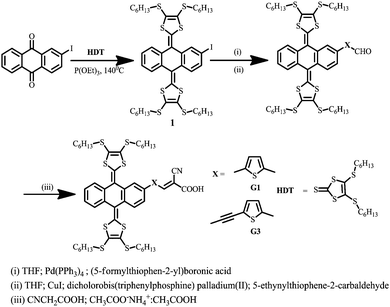
The molecular structure of tetrathiafulvalene with extended π-conjugated based sensitizers (G1 and G3) is shown in Scheme 1.The synthetic pathway to the target sensitizers G1 and G3 is exemplified in Scheme 1, and it involved the Knoevenagel condensation of the exTTF-formyl precursor 2 with cyanoacrylic acid. The former was prepared via a Heck reaction of 1 with either (5-formylthiophen-2-yl)boronic acid or 5-ethylthiophene-2-carbaldehyde using a CuI/Pd(PPh3)2Cl2 catalyst. All precursors are quite soluble in common organic solvents, which allowed easy purification using standard chromatographic techniques, and are spectroscopically characterized (Fig. S1 to S17, ESI†).
Optical & electrochemical properties
To estimate the HOMO and LUMO energy levels and thus evaluate the feasibilities of the two processes including electron injection from the photoexcited dyes to the TiO2 conduction band and dye regeneration, the optical and electrochemical properties of the sensitizers are very essential. The absorbance spectra of the sensitizers in dichloromethane and anchored onto a transparent mesoporous TiO2 film are shown in Fig. 1, and the corresponding data are presented in Table 1. The absorption maxima of G1 at 421 nm (molar extinction coefficient ε = 18![[thin space (1/6-em)]](https://www.rsc.org/images/entities/char_2009.gif) 700 M−1 cm−1) and G3 at 417 nm (ε = 17
700 M−1 cm−1) and G3 at 417 nm (ε = 17![[thin space (1/6-em)]](https://www.rsc.org/images/entities/char_2009.gif) 850 M−1 cm−1) are attributed to π–π* charge transfer transitions in the exTTF chromophores. The red-shift in λmax, when compared to literature reported exTTF based sensitizers, is due to the extended π-conjugation in the π-spacer.22 The red-shift of the absorption maxima of both sensitizers when anchored onto 5 µm thick TiO2 films was attributed to the coupling of the carboxylated moiety with the semiconductor. Fig. 1 also illustrates the emission spectra of G1 and G3 in a DMF solvent at room temperature. Excitation of the absorption maxima resulted in emission spectra having maxima at 601 and 610 nm for G1 and G3, respectively. Based on the optical properties, the E0–0 energy of G1 and G3 is found to be 2.50 ± 0.05, and 2.48 ± 0.05 eV, respectively. A quenched emission spectrum was observed when both of the sensitizers were adsorbed onto a 2 µm thick TiO2 layer as a consequence of electron injection from the excited state of the sensitizer into the conduction of band of TiO2. Also depicted in Fig. 1 are the simulated absorption spectra of both sensitizers obtained from TDDFT calculations.
850 M−1 cm−1) are attributed to π–π* charge transfer transitions in the exTTF chromophores. The red-shift in λmax, when compared to literature reported exTTF based sensitizers, is due to the extended π-conjugation in the π-spacer.22 The red-shift of the absorption maxima of both sensitizers when anchored onto 5 µm thick TiO2 films was attributed to the coupling of the carboxylated moiety with the semiconductor. Fig. 1 also illustrates the emission spectra of G1 and G3 in a DMF solvent at room temperature. Excitation of the absorption maxima resulted in emission spectra having maxima at 601 and 610 nm for G1 and G3, respectively. Based on the optical properties, the E0–0 energy of G1 and G3 is found to be 2.50 ± 0.05, and 2.48 ± 0.05 eV, respectively. A quenched emission spectrum was observed when both of the sensitizers were adsorbed onto a 2 µm thick TiO2 layer as a consequence of electron injection from the excited state of the sensitizer into the conduction of band of TiO2. Also depicted in Fig. 1 are the simulated absorption spectra of both sensitizers obtained from TDDFT calculations.
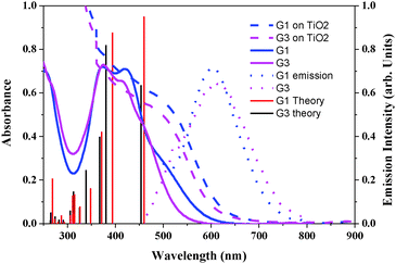 | ||
| Fig. 1 Absorption (left) in CH2Cl2 and emission (right) spectra of G1 and G3 in DMF solvent and adsorbed on a 5 µm thick TiO2 layer. Simulated absorption bands are shown as vertical bars. | ||
| Dye | λ max (nm)/(ɛ M−1 cm−1) | λ (abs. edge on TiO2)a (nm) | λ em (nm) | OX (E1/2 V vs. SCE) | Redc (E1/2 V vs. SCE) | E 0–0 (eV) |
E
Ox*![[thin space (1/6-em)]](https://www.rsc.org/images/entities/char_2009.gif) d (V vs. SCE) d (V vs. SCE) |
|---|---|---|---|---|---|---|---|
| a Absorption spectra were recorded in CH2Cl2 solution, error limits: λmax ±1 nm, ε ±10%. b Solvent: DMF, λmax, ±1 nm. c Solvent: CH2Cl2, error limits: E1/2 ±0.03 V, 0.1 M TBAP. d E Ox* = E0–0-OX; error limits: ±0.05 eV. | |||||||
| G1 |
421 (18![[thin space (1/6-em)]](https://www.rsc.org/images/entities/char_2009.gif) 700) 700)
374 (18 |
720 | 606 | 0.50 | −1.56 | 2.50 | −2.00 |
| G3 |
417 (17![[thin space (1/6-em)]](https://www.rsc.org/images/entities/char_2009.gif) 850) 850)
375 (18 |
720 | 610 | 0.48 | −1.43 | 2.48 | −2.00 |
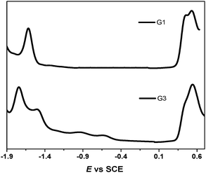
It was reported in the literature that the electrochemical oxidation of the exTTF chromophore was an overall two-electron process occurring with potential inversion; i.e., the second electron is removed more easily than the first. The extent of the potential inversion is estimated to be ∼0.16 V from simulations of cyclic voltammograms.25 The electrochemical properties of the sensitizers were measured with differential pulse and cyclic voltammetry in dichloromethane solution using tetrabutylammonium perchlorate (TBAP) as a supporting electrolyte with an internal reference to the ferrocinium/ferrocene (Fc+/Fc) couple (Fig. 2). Two reversible one-electron oxidations at 0.50 V and 0.58 V for G1 and 0.48 V and 0.59 V for G3 for the successive formation of the TTF radical cation and dication were observed. Consequently, both of the dyes could be regenerated by the I−/I3− redox mediator (−0.21 V vs. Fc+/Fc in ionic liquid).26 The reduction potential (Ered) of the dyes, indicating their lowest unoccupied molecular orbital (LUMO), is considerably more negative than the TiO2 conduction band, providing ample driving force for electron transfer.
Computational study
To gain insight into the electronic properties of the considered organic dyes with π-conjugated spacers, we carried out DFT and TDDFT calculations for both of the sensitizers with a functional basis set of the B3LYP/6-31G(d,p) level. The orbital energy levels in a vacuum, minimum energy conformation (Fig. S19, ESI†), and electron density plots are shown in Fig. 3. The optimized dyes have a flying bird like structure, consisting of hexyl substituted dithiafulvalene at the 9,10 position of anthracene and anchoring groups at the 2nd position. The anthracene moiety is bent perpendicular to the 9th, 10th position axis with an angle of ∼67°, due to steric crowding of the hexyl substituted dithiafulvalene. The steric crowding of the thioalkyl units may possibly retard the recombination of electrons in the TiO2 conduction band with the oxidized dye. A similar steric crowding of alkoxy units over a porphyrin macrocycle was reported by Grätzel and co-workers and they observed a world record efficiency of 13% due to the minimization of recombination of electrons in the TiO2 conduction band with the oxidized porphyrin dye.14 In between the anchoring group (cyanoacrylic acid) and anthracene moiety lie π-conjugated spacers (thiophene or ethynylthiophen) at the 2nd position. The HOMOs of G1 and G3 are at a similar energy level, whereas the LUMO of G1 is lower than that of G3 due to the extended π-conjugation in the spacer. In both cases, the HOMO is delocalized over the anthracene and dithiole units, and the LUMO is delocalized over the π-spacer anchoring group, facilitating electron transfer from the excited state of the sensitizer to the TiO2 conduction band via the carboxylate anchoring group. Based on the experimental observations, TDDFT studies of both molecules were carried out using the B3LYP energy functional with the 6-311G(d,p) basis set in order to gain a deeper understanding of the excited-state transitions, with the framework of the polarizable continuum model (PCM) in dichloromethane solvent. These results are in reasonable agreement with the experimental values (Fig. 1), and the corresponding singlet state properties of both dyes are presented in Table S1 (ESI†).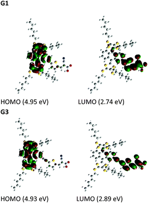 | ||
| Fig. 3 Electronic distribution computed in acetonitrile of the first occupied/unoccupied molecular orbitals of the studied species. | ||
Photovoltaic properties
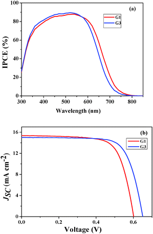
The photovoltaic performance of both of the sensitizers, i.e. the incident photon-to-current conversion efficiency (IPCE) and photocurrent–voltage (J–V) curve, was assessed in test devices using standard mesoporous 8 µm thick TiO2 films and a volatile acetonitrile-based electrolyte composition of 0.6 M 1,2-dimethyl-3-propylimidazolium iodide (DMPII), 0.05 M I2, 0.1 M LiI and 0.5 M 4-tert-butylpyryidine (TBP). The detailed fabrication method was described in our earlier studies.27 The incident photon-to-current conversion efficiency (IPCE) in Fig. 4a shows peak values of 90% at 550 nm for both of the sensitizers. The photoresponse of the thin films displays a broad spectral response covering the entire visible spectrum up to 800 nm. Fig. 4b shows the current–voltage characteristics of the devices using G1 and G3 sensitizers (Table 2). Under standard global Air Mass (AM) 1.5 solar conditions, the G3 sensitizer-based device gave a short-circuit photocurrent density (JSC) of 15.09 ± 0.20 mA cm−2, an open-circuit photovoltage (VOC) of 650 ± 30 mV, and a fill factor (FF) of 0.73 ± 0.03, corresponding to an overall conversion efficiency (η), derived from the equation: η = iSCVOC FF/light intensity, of 7.15%. Under similar test cell conditions G1 has shown a JSC of 15.48 ± 0.20 mA cm−2, a VOC of 601 ± 30 mV, and a FF of 0.71 ± 0.03 with an η of 6.60%.| Sensitizer | J SC (mA) | V OC (V) | FF | η (%) |
|---|---|---|---|---|
| a Photoelectrode: TiO2 (8 + 5 µm and 0.25 cm2). Error limits: JSC = ±0.20 mA cm−2, VOC = ±30 mV, FF = ±0.03. | ||||
| G1 | 15.48 | 0.601 | 0.709 | 6.60 |
| G3 | 15.09 | 0.650 | 0.729 | 7.15 |
The enhanced efficiency of the present exTTF sensitizers, when compared to the literature reported exTTF sensitizers (3.8%), is due to the thioalkyl groups wrapping over the anthracene to prevent the recombination of electrons in the TiO2 conduction band with the oxidized sensitizer. This kind of thioalkyl wrapping protection has not been previously reported for exTTF sensitizers.22
IMVS measurements
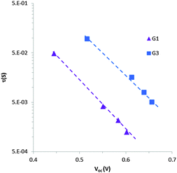
To understand the lower VOC observed for the DSSCs sensitized with the G1 dye compared to G3, we measured the relative conduction band position of TiO2 by means of a charge extraction method. DSSCs sensitized with both G1 and G3 exhibit a similar linear increase in electron density as a function of VOC, indicating that these cells had the same conduction band edge as TiO2 (Fig. 5). The electron lifetime (τ) in DSSCs is a central quantity to determine the dynamics of charge recombination, and is related to the open circuit voltage (VOC) of the cell. We measured the electron lifetime of the DSSCs sensitized with G1 and G3 as a function of VOC by means of an intensity-modulated photovoltage spectroscopy method (Fig. 6). G1 exhibited a shorter τ than the G3 dye at the same electron density, implying that the recombination rate between the electrons on the TiO2 surface and an I3− ion in the electrolyte was higher for G1.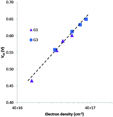 | ||
| Fig. 5 Electron density as a function of open-circuit photovoltage for DSSCs sensitized with G1 & G3. | ||
The shorter electron lifetime in G1 represents a larger electron recombination with I3−, and this contributes to a larger decrease in the Fermi level energy. Note that VOC represents the difference between the Fermi level energy and the Li/I2 electrolyte redox potential. The shorter charge life time in TiO2 for G1 may be due to incomplete dye coverage and/or dye aggregation on the TiO2 surface, which increases the concentration of I3− ions in the vicinity of the TiO2 surface and thus decrease the electron lifetime (τ). To understand the relative dye coverage on the mesoporous TiO2 film of G1 and G3, we measured the amount of adsorbed dye on the TiO2 film. The dye desorption experiment showed that the amount of adsorbed dye is almost the same for both of the G1 and G3 sensitized cells and is calculated to be 1.27 × 10⁻⁷ mol cm−2 and 1.10 × 10⁻⁷ mol cm−2, respectively. Considering the dye adsorption amount and JSC for both of the G1 and G3 sensitized cells, we can expect a similar dye adsorption environment on the TiO2 film for both G1 and G3. Therefore, the lower VOC observed for the DSSCs sensitized with the G1 dye compared to G3 may be due to the intrinsic properties of the G1 and G3 dyes.
Transient absorption studies
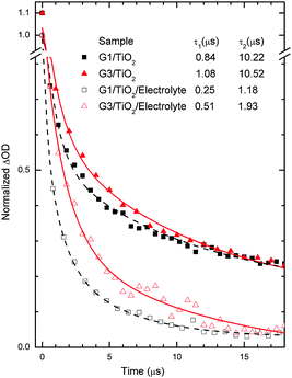
In order to study the electron dynamics of the G1 and G3 dye-sensitized TiO2 films, we have adopted nanosecond transient absorption decay studies (Fig. 7). In the absence of the LiI/I2 electrolyte, the decays of the maximum absorption signals of the dyes (also called bleaching of the ground states of dyes) reflect the dynamics of waste recombination of the photoinjected electrons, in TiO2, with the oxidized dye. Due to the very small ΔOD amplitudes of the transient absorbance signals of the ground state bleaching, we measured instead the lifetime of the oxidative dye formation decays at red shifted absorption spectra (here 700 nm), as seen in our previous work,28 also with N719.29 Importantly, the time needed for dye regeneration is quite similar to the time needed to decay the transient oxidative dye product.29 Transient absorption spectra of the G1 and G3 dyes on TiO2 (in the absence of electrolyte) were fitted using an exponential decay function, y = A1![[thin space (1/6-em)]](https://www.rsc.org/images/entities/char_2009.gif) exp(−t/τ1) + A2
exp(−t/τ1) + A2![[thin space (1/6-em)]](https://www.rsc.org/images/entities/char_2009.gif) exp(−t/τ2) + y0, where A corresponds to amplitude, τ1 denotes the decay time of the excited state (few to hundreds of ns), and τ2 is the waste recombination decay lifetime of the TiO2 photoinjected electrons with the oxidized dye. The spectra of G1/TiO2/electrolyte and G3/TiO2/electrolyte were fitted using the function y = A1
exp(−t/τ2) + y0, where A corresponds to amplitude, τ1 denotes the decay time of the excited state (few to hundreds of ns), and τ2 is the waste recombination decay lifetime of the TiO2 photoinjected electrons with the oxidized dye. The spectra of G1/TiO2/electrolyte and G3/TiO2/electrolyte were fitted using the function y = A1![[thin space (1/6-em)]](https://www.rsc.org/images/entities/char_2009.gif) exp(−t/τ1) + A2
exp(−t/τ1) + A2![[thin space (1/6-em)]](https://www.rsc.org/images/entities/char_2009.gif) exp(−t/τ2) + A3
exp(−t/τ2) + A3![[thin space (1/6-em)]](https://www.rsc.org/images/entities/char_2009.gif) exp(−t/τ3) + y0.6 Here, we mostly use τ2 for dye regeneration by I−. The table inset in Fig. 7 shows different decay constant (τ) values. We are most interested in the decay value τ2, which has a large control of the cell performance.
exp(−t/τ3) + y0.6 Here, we mostly use τ2 for dye regeneration by I−. The table inset in Fig. 7 shows different decay constant (τ) values. We are most interested in the decay value τ2, which has a large control of the cell performance.
The typical half-reaction time τ observed in the absence of the electrolyte is equal to 10.22 µs and 10.52 µs for the G1 and G3 dyes, respectively. The recombination decay times recorded are one fold less than one times those of the typical time constants (10−4 s) for DSSCs under working conditions (1 Sun).6 The relatively lower decay times obtained in our case are mainly due to the use of a high energy laser pulse.
More interesting for the cell performance is the rate of dye regeneration by the electrolyte, which has a large effect on the photogenerated current. In the presence of the LiI/I2 electrolyte (Fig. 7), the decay profile (here for the bleaching of the ground state of the dye) represents dye regeneration through the oxidation of I−. The fitting of the decay profiles observed for the TiO2/dye/electrolyte interface led to regeneration times equal to 1.18 µs and 1.93 µs for the G1 and G3 dyes, respectively. A good corroboration is found here, where faster regeneration decay has allowed for higher current densities, 15.48 mA cm−2 and 15.09 mA cm−2, respectively. This good corroboration between recombination/dye-regeneration kinetics and produced photocurrent decays also indicates good anchoring between the dyes and TiO2 substrate films.
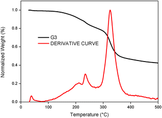
In addition to photovoltaic studies, we have also carried out thermal studies of the newly designed tetrathiafulvalene dyes by using thermogravimetric analysis (TGA). Fig. 8 illustrates TGA curves that were obtained by heating the G3 sensitizer from 35 to 500 °C at a heating rate of 10 °C min−1 under a nitrogen atmosphere. It is known in the literature that tetrathiafulvalene derivatives are thermally stable.30 It is apparent that the thermal behaviour of G1 is stable up to 250 °C, whereas G3 is stable up to 200 °C. The initial weight loss between 200 to 250 °C (5.20%) is due to the removal of moisture. Among metal-free organic sensitizer based DSSCs, tetrathiafulavalene based molecules are thermally stable and this information is useful to carry out durability studies (under thermal stress and light stress) of the devices, which are currently under progress.
Conclusions
In conclusion, we have designed two new metal-free organic sensitizers based on an extended π-conjugated tetrathiafulvalene based scaffold for dye-sensitized solar cell applications with an improved efficiency of 7.15%. The improved efficiency might be due to the presence of thioalkyl groups on tetrathiafulvalene which act as a wrapping to minimize the recombination of electrons in the TiO2 conduction band with the oxidized sensitizer. This class of sensitizers are thermally stable up to 200 °C, which may improve the durability of devices.Experimental section
Materials
Commercially available reagents and chemicals were procured from Sigma-Aldrich. Analytical reagent (AR) grade solvents were used for the reactions while laboratory reagent (LR) grade solvents were used for purifications and column chromatography. Dichloromethane, chloroform, acetonitrile and N,N-dimethyl formamide were dried in the presence of calcium hydride under nitrogen atmosphere. Hexane was purified by Na/benzophenone refluxing overnight, then distilled under vacuum and stored over 4 Å molecular sieves. Triethylamine was distilled over NaOH pellets. ACME silica gel (100–200 mesh) was used for column chromatography. Thin-layer chromatography was performed on Merck-precoated silica gel 60-F254 plates. Either gravity or flash chromatography was performed for the purification of all compounds. All of the reactions were carried out under nitrogen or argon atmosphere using dry and degassed solvents.Synthesis
Compound 2,2′-(2-iodoanthracene-9,10-diylidene)bis(4,5-bis(hexylthio)-1,3-dithiole) (1) was synthesized as per the literature report.22![[thin space (1/6-em)]](https://www.rsc.org/images/entities/char_2009.gif) :
:![[thin space (1/6-em)]](https://www.rsc.org/images/entities/char_2009.gif) 1 (v/v) as the eluent to give the desired compound 2a in 80.5% yield. Anal. calcd for C51H64OS8% (949.57): C, 64.51; H, 6.79. Found C, 64.54; H, 6.81. 1H NMR (300 MHz, CDCl3): 10.1 (s, 1H), 8.0–7.97 (d, 2H), 7.86–7.80 (dd, 3H), 7.72–7.71 (d, 2H), 7.45–7.44 (d, 2H), 7.33–7.31 (dd, 2H), 2.90–2.78 (m, 8H), 1.69–1.61 (m, 24H), 0.89–0.86 (t, 12H); 13C NMR (100 MHz, CDCl3): δ ppm, 184.3, 149.7, 143.6, 140.8, 138.3, 136.4, 134.9, 134.5, 134.3, 133.8, 133.3, 132.9, 132.0, 131.9, 126.9, 126.4, 126.3, 126.2, 125.3, 125.2, 121.0, 121.3, 36.7, 31.3, 29.7, 28.2, 22.8, 14.1. MALDI-TOF MS calcd m/z (C51H64OS8) 949.57, found 949.28.
1 (v/v) as the eluent to give the desired compound 2a in 80.5% yield. Anal. calcd for C51H64OS8% (949.57): C, 64.51; H, 6.79. Found C, 64.54; H, 6.81. 1H NMR (300 MHz, CDCl3): 10.1 (s, 1H), 8.0–7.97 (d, 2H), 7.86–7.80 (dd, 3H), 7.72–7.71 (d, 2H), 7.45–7.44 (d, 2H), 7.33–7.31 (dd, 2H), 2.90–2.78 (m, 8H), 1.69–1.61 (m, 24H), 0.89–0.86 (t, 12H); 13C NMR (100 MHz, CDCl3): δ ppm, 184.3, 149.7, 143.6, 140.8, 138.3, 136.4, 134.9, 134.5, 134.3, 133.8, 133.3, 132.9, 132.0, 131.9, 126.9, 126.4, 126.3, 126.2, 125.3, 125.2, 121.0, 121.3, 36.7, 31.3, 29.7, 28.2, 22.8, 14.1. MALDI-TOF MS calcd m/z (C51H64OS8) 949.57, found 949.28.
General procedure for the synthesis of G1 and G3
Under a N2 atmosphere, corresponding aldehyde (1 mmol), cyanoacetic acid (5 mmol) and ammonium acetate (3 mmol) were dissolved in acetic acid (10 ml) and refluxed for 16 hours. Then the reaction mixture was poured onto ice-cold water, extracted with chloroform and evaporated. The obtained residue was purified by column chromatography using a silica gel, stationary phase and MeOH![[thin space (1/6-em)]](https://www.rsc.org/images/entities/char_2009.gif) :
:![[thin space (1/6-em)]](https://www.rsc.org/images/entities/char_2009.gif) CHCl3 (1
CHCl3 (1![[thin space (1/6-em)]](https://www.rsc.org/images/entities/char_2009.gif) :
:![[thin space (1/6-em)]](https://www.rsc.org/images/entities/char_2009.gif) 10) as the eluent to give corresponding G1 and G3.
10) as the eluent to give corresponding G1 and G3.
Methods and instrumentation
1H-NMR spectra were recorded on a 500 MHz INOVA spectrometer. Differential pulse voltammetric measurements were performed on a PC-controlled electrochemical analyser (CH instruments model CHI620C). All of these experiments were conducted with a 1 mM concentration of compounds in DMF at a scan rate of 10 mV s−1 in which tetrabutylammonium hexafluorophosphate (TBAP) was used as a supporting electrolyte. The working electrode was glassy carbon, a standard calomel electrode (SCE) was the reference electrode and Pt wire was the auxillary electrode. The optical absorption spectra were recorded on a Shimadzu (Model UV-3600) spectrophotometer. Steady-state fluorescence spectra were recorded on a Fluorolog-3 spectrofluorometer (Spex model, JobinYvon) for solutions with optical density at a wavelength of excitation (λex) ≈ 0.05. Thermogravimetric measurements were carried out on a Mettler Toledo TGA/SDTA 851e instrument with a heating rate of 10 °C min−1 with 10 mg of sample under a nitrogen atmosphere.Computational methodology
All of the calculations have been carried out using a Gaussian 09 package31 on a personal computer. The ground state geometry of both of the sensitizers G1 and G3 was optimized using density functional theory (DFT), while time-dependent DFT (TDDFT) was employed for the estimation of ground to excited-state transitions. The obtained geometries were to be genuine global minimum structures, using the B3LYP hybrid functional32 and 6-31G(d,p) basis set33, and were used as the input for further calculations. The geometries were then used to obtain frontier molecular orbitals (FMOs) and were also subjected to single-point TDDFT studies (first 15 vertical singlet–singlet transitions) to obtain the UV-Vis spectra of the dyes. The integral equation formalism polarizable continuum model (PCM)34,35 within the self-consistent reaction field (SCRF) theory was used in the TDDFT calculations to describe the solvation of the dyes in dichloromethane. The software GaussSum 2.2.5 was employed to simulate the major portions of the absorption spectra and to interpret the nature of transitions.36,37 The contribution percentages of individual units present in the dyes to the respective molecular orbitals were calculated.Transient absorption spectroscopy
A laser flash photolysis spectrometer (model LP920, Edinburg) has been used. It was associated with a Continuum Nd-YAG laser (Surelite; 10 Hz repetition rate; FWHM 5 ns). A Surelite optical parametric oscillator permits the conversion of the second harmonic to a visible spectrum of 400–820 nm. TiO2 samples (12 µm) sensitized with different dyes were subjected to 6 mJ cm−2 flash photolysis. The respective dyes were excited at 445 nm. The excited state decay of the dye and the recovery of its fundamental state were monitored by the change in the absorbed continuous wave light. A satisfactory signal-to-noise ratio was obtained by averaging the absorption spectra for 100–200 laser shots.CEM and IMVS measurements
The intensity-modulated photovoltage spectroscopy (IMVS) was measured with a potentiostat (Solartron1287) equipped with a frequency response analyzer (Solartron1255B) at an open-circuit condition, based on a monochromatic illumination (420 nm) controlled by a Labview system, to obtain the photovoltaic response induced by the modulated light. The modulated light was driven with a 10% AC perturbation current superimposed on a DC current in a frequency range from 0.1 to 106 Hz. The charge extraction method (CEM) was performed with the same monochromatic light source. The solar cell was illuminated at an open-circuit condition for 5 s to attain a steady state and then the light source was switched off when the device simultaneously switched to a short-circuit condition to extract the charges generated at that light intensity.Device fabrication and photovoltaic performance measurements
The TiO2 photoanode was prepared as reported previously.27 A fluorine-doped tin oxide (FTO) conducting glass substrate with a resistance of ∼10 Ohm−2 was used. A screen printed double layer TiO2 film of (8 + 5) µm in thickness (0.25 cm2 cell area) with an 8 µm transparent layer of TiO2 particles (approximately 20 nm in diameter) and a 5 µm scattering layer of TiO2 particles (approximately 400 nm in diameter) was prepared. The films were sintered at 500 °C for 1 h. The thickness of the films was measured with a Surfcom 1400A surface profiler (Tokyo Seimitsu Co. Ltd). A 0.2 mM solution of dye in 1![[thin space (1/6-em)]](https://www.rsc.org/images/entities/char_2009.gif) :
:![[thin space (1/6-em)]](https://www.rsc.org/images/entities/char_2009.gif) 1 (v/v) acetonitrile/tert-butyl alcohol was used to coat the TiO2 film. The TiO2 films were immersed in the dye solutions and then kept at 25 °C for 15 h. To assemble each cell, each dye-coated TiO2 film and a platinum-coated conducting glass were separated by a Surlyn spacer (40 µm thick) and sealed by heating the polymer frame at 100 °C. An electrolyte consisting of a mixture of 0.6 M dimethylpropyl-imidazolium iodide, 0.05 M I2, 0.1 M LiI, and 0.5 M tert-butylpyridine in acetonitrile was used in each cell. G1 and G3 were desorbed from the TiO2 film by immersing the TiO2 film in 0.1 M TBAOH solution (1
1 (v/v) acetonitrile/tert-butyl alcohol was used to coat the TiO2 film. The TiO2 films were immersed in the dye solutions and then kept at 25 °C for 15 h. To assemble each cell, each dye-coated TiO2 film and a platinum-coated conducting glass were separated by a Surlyn spacer (40 µm thick) and sealed by heating the polymer frame at 100 °C. An electrolyte consisting of a mixture of 0.6 M dimethylpropyl-imidazolium iodide, 0.05 M I2, 0.1 M LiI, and 0.5 M tert-butylpyridine in acetonitrile was used in each cell. G1 and G3 were desorbed from the TiO2 film by immersing the TiO2 film in 0.1 M TBAOH solution (1![[thin space (1/6-em)]](https://www.rsc.org/images/entities/char_2009.gif) :
:![[thin space (1/6-em)]](https://www.rsc.org/images/entities/char_2009.gif) 1 mixture of H2O and ethanol). The amount of adsorbed dye was estimated from the absorption peak of each resulting solution.
1 mixture of H2O and ethanol). The amount of adsorbed dye was estimated from the absorption peak of each resulting solution.
The current–voltage characteristics were measured using a black metal mask with an area of 0.25 cm2 under AM 1.5 sunlight (100 mW cm−2, WXS-155S-10: Wacom Denso Co. Japan). The IPCE spectra were measured with a monochromatic incident light of 1 × 10¹⁶ photons cm−2 in direct current mode (CEP-2000BX, Bunko-Keiki).
Acknowledgements
We thank CSIR-NISE and the Department of Science & Technology (DST) and the Government of India under the major project DST-UK (‘APEX’) for the financial support to carry out this work. Author N. Duvva thanks CSIR for a junior research fellowship. A. Islam acknowledges the support from the JSPS KAKENHI grant No. 26288113. A. Islam and I. Bedja extend their appreciation to the International Scientific Partnership Program ISPP at King Saud University for funding this research work through ISPP #0019.Notes and references
- M. Ye, X. Wen, M. Wang, J. Locozzia, N. Zhang, Ch. Lin and Z. Lin, Mater. Today, 2015, 18, 155–162 CrossRef CAS.
- H. A. Harms, N. Tetreault, N. Pellet, M. Bensimon and M. Grätzel, Faraday Discuss., 2014, 176, 251–269 RSC.
- V. K. Singh, R. K. Kanaparthi and L. Giribabu, RSC Adv., 2014, 4, 6970–6984 RSC.
- Ch. Qin, W.-Y. Wong and L. Han, Chem. – Asian J., 2013, 8, 1706–1719 CrossRef CAS PubMed.
- Y.-S. Yen, H.-H. Chou, Y. C. Chen, C. Y. Hsu and J. T. Lin, J. Mater. Chem., 2012, 22, 8734–8747 RSC.
- A. Haegfeldt, G. Boschloo, L. Sun, L. Kloo and H. Pettersson, Chem. Rev., 2010, 110, 6595–6663 CrossRef PubMed.
- B. O'Regan and M. Grätzel, Nature, 1991, 353, 737–740 CrossRef.
- M. K. Nazeeruddin, A. Kay, I. Rodicio, R. Humphry-baker, E. Muller, P. Liska, N. Vlachopoulos and M. Grätzel, J. Am. Chem. Soc., 1993, 115, 6382–6390 CrossRef CAS.
- L. Han, A. Islam, H. Chem, M. Chandrasekharam, B. Chiranjeevi, S. Zhang, X. Wang and M. Yanagida, Energy Environ. Sci., 2012, 5, 6057–6060 CAS.
- L. Giribabu, R. K. Kanaparthi and V. Velkannan, Chem. Rec., 2012, 12, 306–328 CrossRef CAS PubMed.
- R. K. Kanaparthi, J. Kandhadi and L. Giribabu, Tetrahedron, 2012, 68, 8383–8393 CrossRef CAS.
- A. Mishra, M. K. R. Fischer and P. Bauerle, Angew. Chem., Int. Ed., 2009, 48, 2474–2499 CrossRef CAS PubMed.
- N. Duvva, R. K. Kanaparthi, J. Kandhadi, G. Marotta, P. Salvatori, F. DeAngelis and L. Giribabu, J. Chem. Sci., 2015, 127, 383–394 CrossRef CAS.
- S. Mathew, A. Yella, P. Gao, R. Humphry-Baker, B. F. E. Curchod, N. Ashari-Astani, I. Tavernelli, U. Rothlisberger, M. K. Nazeeruddin and M. Grätzel, Nat. Chem., 2014, 6, 242–247 CrossRef CAS PubMed.
- Z. Wan, Ch. Jia, Y. Duan, L. Zhou, Y. Lin and Y. Shi, J. Mater. Chem., 2012, 22, 25140–25147 RSC.
- A. El-Shafei, M. Hussain, A. Atiq, A. Islam and L. Han, J. Mater. Chem., 2012, 22, 24048–24056 RSC.
- J.-H. Yum, E. Baranoff, F. Kessler, T. Moehl, S. Ahmad, T. Bessho, A. Marchioro, E. Ghadiri, J.-E. Moser, Ch. Yi, M. K. Nazeeruddin and M. Grätzel, Nat. Commun., 2012, 3, 631 CrossRef PubMed.
- N. Martin, L. Sanchez, M. A. Herranz, B. Illescas and D. M. Guldi, Acc. Chem. Res., 2007, 40, 1015–1024 CrossRef CAS PubMed.
- J. L. Segura and N. Martin, Angew. Chem., Int. Ed., 2001, 40, 1372–1409 CrossRef CAS.
- M. A. Herranz, N. Martin, J. Ramey and D. M. Guldi, Chem. Commun., 2002, 2968–2969 RSC.
- F. Giacalone, J. L. Segura, N. Martin, J. Ramey and D. M. Guldi, Chem. – Eur. J., 2005, 11, 4819–4834 CrossRef CAS PubMed.
- S. Wenger, P.-A. Bouit, Q. Chen, J. Teuscher, D. DiCenso, R. Humphry-Baker, J.-E. Moser, J. L. Delgado, N. Martin, S. M. Zakeeruddin and M. Grätzel, J. Am. Chem. Soc., 2010, 132, 5164–5169 CrossRef CAS PubMed.
- Y. Geng, F. Pop, Ch. Yi, N. Avarvari, M. Grätzel, S. Decurtins and S.-X. Liu, New J. Chem., 2014, 38, 3269–3274 RSC.
- A. Amacher, Ch. Yi, J. Yang, M. P. Bircher, Y. Fu, M. Cascella, M. Grätzel, S. Decurtins and S.-X. Liu, Chem. Commun., 2014, 50, 6540–6542 RSC.
- P. Wang, S. M. Zakeeruddin, J.-E. Moser and M. Grätzel, J. Phys. Chem. B, 2003, 107, 13280–13285 CrossRef CAS.
- R. Kawano and M. Watanabe, Chem. Commun., 2003, 330–331 RSC.
- T. Jella, M. Srikanth, R. Bolligarla, Y. Soujanya, S. P. Singh and L. Giribabu, Dalton Trans., 2015, 44, 14697–14706 RSC.
- G. H. Rao, A. Venkateswararao, L. Giribabu, L. Han, I. Bedja, R. K. Gupta, A. Islam and S. P. Singh, Phys. Chem. Chem. Phys., 2016, 15, 287–296 CAS.
- G. Boschloo and A. Hagfeldt, Chem. Phys. Lett., 2003, 370, 381–386 CrossRef CAS.
- Y. Wang and Y. Zhao, Beilstein J. Org. Chem., 2015, 11, 957–965 CrossRef CAS PubMed.
- M. J. Frisch, G. W. Trucks, H. B. Schlegel, G. E. Scuseria, M. A. Robb, J. R. Cheeseman, G. Scalmani, V. Barone, B. Mennucci, G. A. Petersson, H. Nakatsuji, M. Caricato, X. Li, H. P. Hratchian, A. F. Izmaylov, J. Bloino, G. Zheng, J. L. Sonnenberg, M. Hada, M. Ehara, K. Toyota, R. Fukuda, J. Hasegawa, M. Ishida, T. Nakajima, Y. Honda, O. Kitao, H. Nakai, T. Vreven, J. A. Montgomery Jr, J. E. Peralta, F. Ogliaro, M. Bearpark, J. J. Heyd, E. Brothers, K. N. Kudin, V. N. Staroverov, R. Kobayashi, J. Normand, K. Raghavachari, A. Rendell, J. C. Burant, S. S. Iyengar, J. Tomasi, M. Cossi, N. Rega, N. J. Millam, M. Klene, J. E. Knox, J. B. Cross, V. Bakken, C. Adamo, J. Jaramillo, R. Gomperts, R. E. Stratmann, O. Yazyev, A. J. Austin, R. Cammi, C. Pomelli, J. W. Ochterski, R. L. Martin, K. Morokuma, V. G. Zakrzewski, G. A. Voth, P. Salvador, J. J. Dannenberg, S. Dapprich, A. D. Daniels, O. Farkas, J. B. Foresman, J. V. Ortiz, J. Cioslowski and D. J. Fox, Gaussian 09, Revision B.01, Gaussian, Inc., Wallingford CT, 2010 Search PubMed.
- A. D. Becke, J. Chem. Phys., 1993, 98, 5648–5652 CrossRef CAS.
- G. A. Petersson and M. A. Al-Laham, J. Chem. Phys., 1991, 94, 6081–6090 CrossRef CAS.
- S. Miertus, E. Scrocco and J. Tomasi, J. Chem. Phys., 1981, 55, 117–129 CAS.
- M. Cossi, V. Barone, R. Cammi and J. Tomasi, Chem. Phys. Lett., 1996, 255, 327–335 CrossRef CAS.
- N. M. O'Boyle, A. L. Tenderholt and K. M. Langner, J. Comput. Chem., 2008, 29, 839–845 CrossRef PubMed.
- R. Dennington, T. Keith and J. Millam, GaussView, version 5, Semichem, Inc., Shawnee Mission KS, 2009 Search PubMed.
Footnote |
| † Electronic supplementary information (ESI) available: Full synthetic details. See DOI: 10.1039/c6qm00070c |
| This journal is © the Partner Organisations 2017 |

