 Open Access Article
Creative Commons Attribution 3.0 Unported Licence
Ag–CuO–ZnO metal–semiconductor multiconcentric nanotubes for achieving superior and perdurable photodegradation†
Kaichen
Xu‡
 ab,
Jiagen
Wu‡
b,
Chuan Fu
Tan
a,
Ghim Wei
Ho
 a,
Ang
Wei
*b and
Minghui
Hong
 *a
*a
aDepartment of Electrical and Computer Engineering, National University of Singapore, 4 Engineering Drive 3, 117576, Singapore. E-mail: elehmh@nus.edu.sg
bKey Laboratory for Organic Electronics and Information Displays & Institute of Advanced Materials (IAM), National Synergistic Innovation Center for Advanced Materials (SICAM), Nanjing University of Posts & Telecommunications, 9 Wenyuan Road, Nanjing 210023, China. E-mail: iamawei@njupt.edu.cn
First published on 14th July 2017
Abstract
Solar energy represents a robust and natural form of resource for environment remediation via photocatalytic pollutant degradation with minimum associated costs. However, due to the complexity of the photodegradation process, it has been a long-standing challenge to develop reliable photocatalytic systems with low recombination rates, excellent recyclability, and high utilization rates of solar energy, especially in the visible light range. In this work, a ternary hetero-nanostructured Ag–CuO–ZnO nanotube (NT) composite is fabricated via facile and low-temperature chemical and photochemical deposition methods. Under visible light irradiation, the as-synthesized ZnO NT based ternary composite exhibits a greater enhancement (∼300%) of photocatalytic activity than its counterpart, Ag–CuO–ZnO nanorods (NRs), in pollutant degradation. The enhanced photocatalytic capability is primarily attributed to the intensified visible light harvesting, efficient charge carrier separation and much larger surface area. Furthermore, our as-synthesised hybrid ternary Ag–CuO–ZnO NT composite demonstrates much higher photostability and retains ∼98% of degradation efficiency even after 20 usage cycles, which can be mainly ascribed to the more stable polar planes of ZnO NTs than those of ZnO NRs. These results afford a new route to construct ternary heterostructured composites with perdurable performance in sewage treatment and photocorrosion suppression.
1. Introduction
The extensive utilization of fossil fuels, deterioration of the environment and global warming advocate increasing the demand to seek sustainable green strategies based on energy conversion.1,2 Fortunately, natural resources, such as wind,3 water wave4 and solar energy,5,6 endow human beings with abundant pathways to access renewable and clean resources. In particular, in order to address the primary issue of water pollution, solar energy coupled with novel semiconductor photocatalysts has attracted considerable research interest via mimicking natural photosynthesis.7,8 Relying on the photogeneration of electron–hole pairs in light-harvesting systems, a photodegradation reaction takes place, which is capable of eliminating organic contaminants in waste streams.9,10 In recent years, one-dimensional (1D) nanostructure-based photocatalysts have attracted tremendous research attention owing to their high aspect ratio and excellent carrier transport performance.11–15 Among the variety of 1D metal–oxide based photocatalysts, zinc oxide (ZnO) nanorods (NRs), as an n-type single crystal semiconductor, have been envisioned as a promising and efficient candidate in environmental remediation systems owing to its fascinating features, including non-toxicity, high electron mobility, strong oxidation ability, environmentally friendly property and good photocatalytic capability.16–18Nevertheless, there are several intrinsic drawbacks of ZnO NRs, restricting their practical application in water purification. For instance, the wide bandgap (∼3.37 eV) of ZnO results in its sole absorption of UV light, which accounts for a limited portion (∼4%) of the solar spectrum.19 Furthermore, the electron–hole separation efficiency of ZnO is very poor, leading to the degradation of its photocatalytic efficiency.20 In addition, due to the photo-generated holes, the high rate of photocorrosion in nanosized ZnO materials gives rise to their poor photo-stability in aqueous solution.21 These critical issues primarily inhibit the photocatalytic performance of ZnO in environmental remediation. Therefore, in order to boost the photocatalytic capability of ZnO-based photocatalysts, tremendous effort has been devoted to extending their optical absorption range, boosting the separation efficiency of the photogenerated carriers and improving the photo-stability.8,18,22,23 One of the promising strategies is to couple noble metals, such as gold (Au) or silver (Ag), with ZnO nanostructures.18,24–26 The metal nanoparticles can facilitate light–matter interactions owing to the effective surface plasmon resonance, contributing to the enhanced absorption of visible light.27,28 Furthermore, the unique semiconductor–metal interfaces allow the formation of a Schottky barrier, which promotes the charge separation efficiency.29,30 Another intriguing method is to employ binary p–n heterostructures composed of narrow- and wide-bandgap ZnO semiconductors. p-Type narrow-bandgap semiconductors, such as copper oxide (CuO) or cuprous oxide (Cu2O), can not only optimize the visible light activation, but also enable the opposite propagation of positive and negative charge carriers across the hetero-interface, giving rise to a high charge-separation efficiency.31,32
However, the perdurable property of the ZnO-based photocatalysts has not been well realized, which is of paramount significance for their practical application in the removal of pollutants, especially for multiple uses, which would need photo-degradation for a much longer time. Such highly recyclable and photo-stable photocatalytic systems require the composites to be provided with a strong anti-photocorrosion characteristic. Although various studies have been performed to overcome the limitation of photocorrosion via surface modification with a passive layer, such as carbon,33 reduced graphene oxide,34 graphene17 and polyaniline,35 most of these studies conducted recycling photostability tests with fewer than five cycles.36,37 As a matter of fact, the performance of ZnO NRs-based systems suffers from significant degradation during the long and repeated photocatalytic process.21 This phenomenon can be ascribed to two main factors. First, the strong oxidative capability of photogenerated active oxygen species can oxidize carbon or organic composites, leading to the suppression of the photocatalytic stability.21 Second, conventional studies focus on the amelioration of ZnO NR-based photocatalysts. However, the high surface energy of (0001)-Zn and (000–1)-O for ZnO NRs makes them unstable during the photodegradation process.38 In contrast, their counterpart ZnO nanotubes (NTs) have great potential to overcome the aforementioned issue owing to the lower surface energy (J m−2) of the polar surface (10–10).38,39 Moreover, the efficient carrier extraction and the larger surface area of ZnO NTs empower them to be promising backbones for practical photocatalysts.15,39,40
In this work, a new type of 1D ternary photosynthetic composite for efficient and perdurable photodegradation is developed via facile low-temperature chemical and photochemical deposition approaches based on a unique metal–semiconductor system. In such ternary hybrids, vertically aligned ZnO NTs are employed as the building block. CuO and Ag nanoparticles are then decorated onto the surface of ZnO NTs. The as-fabricated ternary Ag–CuO–ZnO NT arrays demonstrated enhanced photocatalytic performance (∼300%) to decompose methyl orange (MO) and Rhodamine B (RhB) in water driven by visible light, as compared with that of ternary Ag–CuO–ZnO NRs arrays, binary Ag–ZnO (NTs & NRs) and CuO–ZnO (NTs & NRs) composites. This is ascribed to the synergistic effects of the intensified visible light harvesting, high charge-separation efficiency and large surface area of Ag–CuO–ZnO NTs systems. Furthermore, the hybrid structures of ternary ZnO NT-based composites exhibit excellent recyclability due to the strong anti-photocorrosion property of the ZnO NTs as well as the formation of CuO films as a protective layer. Such perdurable photodegradation capability of photocatalysts enables them to serve as a potential means for decomposing persistent organic species in environmental remediation.
2. Experimental details
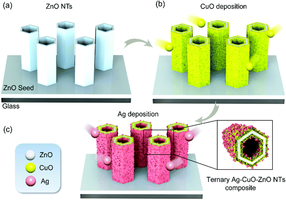
The fabrication of ternary Ag–CuO–ZnO NT array composites consists of three main steps: the preparation of ZnO NT arrays and then photodeposition of CuO and Ag nanoparticles as illustrated in Fig. 1. The details of the fabrication procedures are as follows.2.1. Preparation of ternary photocatalysts
2.2. Characterization
The crystal structures of the hybrid ternary composites are studied by X-ray diffraction (XRD, Siemens D5005) analysis with CuKα radiation. The XPS spectra of the products are characterized by using a PerkinElmer PHI 5000 C ESCA system provided with a hemispherical electron energy analyzer. The surface morphology of the samples is revealed by scanning electron microscopy (SEM, S4800). Transmission electron microscopy (TEM) and high-resolution electron microscopy (HRTEM) images as well as selected area electron diffraction (SAED) patterns are obtained with a Tecnai G2 F20 S-TWIN. The UV-Vis absorption spectra are measured by using a UV-2401PC spectrometer. A Brunauer–Emmett–Teller (BET) approach is used to calculate the specific surface area tested by a specific surface area and pore size analyzer (2800P V-Sorb). The time-dependent photocurrent is measured on a three-electrode cell using Pt as the counter electrode and Ag/AgCl as the reference electrode at a fixed bias of 0.6 V and Na2SO4 (0.1 M) is applied as the electrolyte. A 300 W xenon arc lamp system (intensity: 100 mW cm−2) is used as the irradiation source. Electrochemical impedance spectroscopy (EIS) tests are performed on a CHI-660D workstation (CH Instruments).2.3. Photocatalytic activity
Rhodamine B (RhB) and methyl orange (MO) are two common pollutants in waste streams, which are chosen to compare the photocatalytic characteristics of Ag–CuO–ZnO NTs and Ag–CuO–ZnO NRs. Taking MO as an example, the samples are grown on a glass substrate with the same effective area (2.0 cm × 2.0 cm) and are immersed in a MO solution (30 mL) at a concentration of 2 × 10⁻⁵ M. The mass of the photocatalysts for all photodegradation steps is in the range of 25 to 30 mg. A visible light source from 420 nm to 720 nm is achieved by applying a xenon lamp equipped with a 420 nm cut-off filter. Before the photodegradation, the MO solution is retained in the dark (30 min) to reach the adsorption–desorption equilibrium. Visible light with an intensity of ∼50 mW cm−2 is then focused at the sample surface. The UV-Vis spectrophotometer is applied every 10 min to determine the concentration of MO. After the measurements, irradiation is resumed. To make a comparison, the photocatalytic efficiency of the bare ZnO NTs and NRs, binary CuO–ZnO NTs and NRs as well as binary Ag–ZnO NTs and NRs is also characterized.To demonstrate the recyclability of ternary ZnO-based composites, the as-fabricated products are placed in a MO solution (30 mL) at a concentration of 2 × 10⁻⁵ M driven by the irradiation of visible light for 20 usage cycles. For each round, the MO solution is catalyzed by Ag–CuO–ZnO NTs and NRs for 60 min and then its absorption peak at a wavelength of ∼460 nm is measured. In the next cycle, the new solution takes the place of the old one and then the same procedure is carried out.
3. Results and discussion
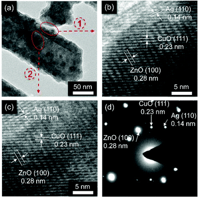
To reveal the surface morphology of the ternary Ag–CuO–ZnO photocatalysts, the as-synthesised nanostructures are characterized by SEM. As can be observed in Fig. 2a, obviously, the wurtzite ZnO forms a tubular structure with an average tube wall thickness of 8 nm, an external diameter of around 50 nm and a length of around 200 nm. It should be noted that the external diameter and length of ZnO NTs are similar to those of ZnO NRs (Fig. S1†). Furthermore, the vertically aligned ZnO NTs array is perpendicular to the glass substrate in the c-axis direction with a smooth surface (inset of Fig. 2a). Noticeably, the pH value plays a significant role in influencing the morphology of ZnO NTs. The fabrication procedure with the lower pH values leads to a non-continuous ZnO NTs array, while the higher pH values result in failure to form tubular structures.38 Employing the as-fabricated ZnO NT array as the building block, CuO nanoparticles are then photodeposited onto the surface of ZnO NTs to allow the formation of the binary CuO–ZnO NT composite driven by UV light irradiation (Fig. 2b). Under the sustained UV irradiation, more CuO particles are obtained, leading to a thicker and relatively rougher CuO layer covered on the surfaces of ZnO NTs (inset of Fig. 2b). After the decoration of Ag nanoparticles, grainy materials are observed on the surface of CuO–ZnO NTs (Fig. 2c and c, inset), indicating the formation of ternary Ag–CuO–ZnO NT composites. To make a comparison and exhibit the superior photocatalytic performance of ZnO NTs-based composites, ZnO NR-based compounds are also synthesized using similar procedures and their surface morphology is shown in Fig. S1.†The morphology of the ternary ZnO NT-based composite is further elucidated by TEM analyses. Fig. 3a depicts a characteristic TEM image of hetero-nanostructured Ag–CuO–ZnO NTs. As can be seen, ZnO NTs exhibit 1D structures with a well-defined hollow morphology, and serve as the building block for the formation of core–shell architectures. Fig. 3b and c show high-resolution TEM (HRTEM) images of the ZnO NT core and CuO and Ag shells in the inner and outer surfaces. The lattice spacing of around 0.28 nm, 0.23 nm and 0.14 nm represents the (100) plane of ZnO, the (111) plane of CuO and the (110) plane of Ag, respectively. The corresponding SAED patterns further confirm the successful preparation of Ag–CuO–ZnO NTs (Fig. 3d). These results indicate that vertically aligned ZnO NTs are obtained with the CuO and Ag nanoparticles existing on the outer and inner surfaces.
The crystallographic structures of the ternary composites are investigated by XRD analyses. It is seen from Fig. 4a that the diffraction peaks of wurtzite ZnO (JCPDS no. 36-1451) can be measured from both ternary composites based on ZnO NRs (top graph) and ZnO NTs (bottom graph). This observation also indicates that the structures of ZnO NRs and NTs are retained well after the photodeposition of CuO and Ag nanoparticles, which correspond to the SEM and TEM results as illustrated above. Notably, the (002) peak intensity of ZnO NTs becomes much weaker in comparison with that of ZnO NRs (indicated by the red circle), implying the elimination of the (00l) planes of ZnO NTs.38 In addition, three diffraction peaks (110), (111), (113) (JCPDS no. 48-1548) of CuO and two diffraction peaks (103) and (110) (JSPDS no. 41-1402) of Ag are observed, revealing that the as-fabricated ternary Ag–CuO–ZnO composites have excellent crystalline structures. Furthermore, XPS spectra are recorded to identify the chemical constituents and valence states of the ternary Ag–CuO–ZnO NT composite. Fig. 4b exhibits the typical XPS survey spectra, which demonstrate the high purity of the hybrid nanostructures, including the elements Zn, Cu, O and Ag. The peaks at 1044.6 eV and 1021.5 eV correspond to asymmetric peaks of Zn 2p1/2 (1044.6 eV) and Zn 2p3/2 (1021.5 eV), respectively (Fig. 4c).36 The two typical peaks of Cu 2p3/2 (933.8 eV) and Cu 2p1/2 (953.9 eV) as well as the satellite peak at 943 eV confirm the oxidation states of Cu2+ rather than Cu1+ (Fig. 4d).41 The binding energies of 374 eV and 368 eV are in accordance with the Ag 3d3/2 and Ag 3d5/2 with a splitting energy of 6 eV, indicating the existence of metallic Ag (Fig. 4e).24 The XRD and XPS analyses above further identify the coexistence of ZnO, CuO, and Ag in the as-synthesised photocatalysts.
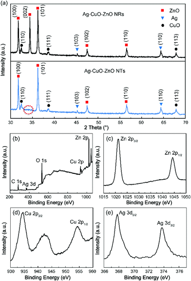 | ||
| Fig. 4 (a) XRD patterns of the ternary Ag–CuO–ZnO NRs and Ag–CuO–ZnO NTs. XPS spectra of Ag–CuO–ZnO NTs. (b) Survey, (c) Zn 2p, (d) Cu 2p, (e) Ag 3d. | ||
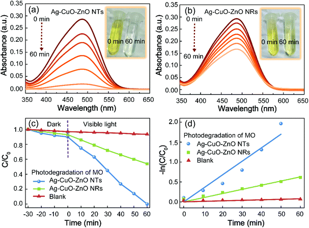
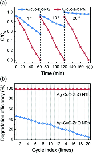
The photocatalytic capability of the ZnO-based compound is evaluated towards the reduction of MO, a hazardous dye applied in the textile industry. Before gaining insight into the ternary catalysts, the photocatalytic activities of bare ZnO NTs (NRs), binary CuO–ZnO NTs (NRs) and binary Ag–ZnO NTs (NRs) driven by visible light irradiation (420–720 nm) are firstly investigated (Fig. S4†). It is found that bare ZnO NTs or NRs exhibit minimum degradation efficiency as compared to their corresponding binary composites, which is attributed to the poor efficiency of utilization of the visible light because of the wide bandgap and low charge-separation efficiency. Noticeably, the photocatalytic performance of bare ZnO NTs is slightly higher in comparison with that of bare ZnO NRs. This is primarily ascribed to the larger surface area of ZnO NTs with more active sites. The decoration of CuO or Ag nanoparticles onto the surface of ZnO NRs or NTs is capable of moderately improving the photocatalytic efficiency. Such observation is primarily due to the fact that the introduction of CuO or Ag allows the formation of the heterojunction or the Schottky barrier, resulting in higher charge-separation efficiency.29–31 Particularly, the ternary Ag–CuO–ZnO NT composite demonstrates optimal photocatalytic performance. To be specific, Fig. 5a and b show the absorption spectra of MO at different time intervals when degraded by Ag–CuO–ZnO NTs and Ag–CuO–ZnO NRs, respectively. After a reaction for 1 h under visible light irradiation, there is almost no absorption peak observed at 464 nm for the ternary catalyst of Ag–CuO–ZnO NTs, indicating the complete degradation of the dyes. However, the absorption intensity for MO catalysed by Ag–CuO–ZnO NRs only decreases from ∼30% to ∼16%. The time-dependent concentration of MO relative to its initial concentration (C/C0) without the catalyst and in the presence of the ternary ZnO-based composites is depicted in Fig. 5c. Importantly, the degradation of ternary Ag–CuO–ZnO NTs is much faster than that of Ag–CuO–ZnO NRs driven by visible light irradiation, even in a dark environment. Fig. 5d exhibits the kinetic behaviors of MO degradation by the ternary ZnO-based composites.
The pseudo-first-order kinetics of the ternary ZnO-based photocatalysts are investigated via employing the pseudo-first-order model as follows:42
 | (1) |
In order to untangle the origin of the enhanced photocatalytic performance of the ternary Ag–CuO–ZnO NTs towards the reduction of MO in comparison with that of bare ZnO, binary ZnO-based composites as well as ternary Ag–CuO–ZnO NRs, UV-Vis absorbance spectra of the composites are measured (Fig. 6). It is clearly seen that because of its wide bandgap, the ZnO NR array only shows a response to UV light (<∼380 nm). When ZnO NTs are formed, the absorption is slightly increased in the visible range. Such an increase can be ascribed to the larger optical path lengths of photons, leading to the higher probability of absorption, which, in turn, contributes to larger scale production of electron–hole pairs and higher photodegradation efficiency than that of ZnO NRs.43 After the decoration of CuO nanoparticles, the heterojunction structures are formed and the absorption for both binary CuO–ZnO NTs and NRs is enhanced, which is attributed to the narrow bandgap of CuO (∼1.7 eV).31 As for the absorption spectra of ternary composites, there is a typical surface plasmon resonance (SPR) peak at around 440 nm, further confirming that Ag nanoparticles are successfully deposited onto the binary CuO–ZnO composites. The characteristic SPR band extends the absorption of ternary Ag–CuO–ZnO NTs and NRs in the visible range, which promotes the generation of charge carriers to boost the photocatalytic performance.44,45 Furthermore, the BET surface area is also studied to reveal the causes of enhanced photocatalytic efficiency of Ag–CuO–ZnO NTs. It can be found from Table 1 that Ag–CuO–ZnO NTs are endowed with a surface area of 19.85 m2 g−1, which is nearly 11 times larger than that of Ag–CuO–ZnO NRs. The larger surface area affords a variety of active sites for the photochemical reaction, contributing to the diffusion and transportation of dye pollutants and higher photocatalytic efficiency.46,47 To further reveal the advantages of the ternary Ag–CuO–ZnO NTs over the Ag–CuO–ZnO NRs in photocatalytic activity, photoelectrochemical analysis is also performed. It is found that the photocurrent density of the Ag–CuO–ZnO NTs is much higher than that of the Ag–CuO–ZnO NRs, indicating more efficient separation of photogenerated charge carriers on the Ag–CuO–ZnO NTs (Fig. S8(a)†).17,25,30 Furthermore, it can be observed from EIS Nyquist plots that the ternary Ag–CuO–ZnO NTs exhibit smaller semicircles at higher frequencies in comparison with the ternary Ag–CuO–ZnO NRs, which reveals that more efficient interfacial transportation as well as separation of photogenerated electron–hole pairs are achieved over the Ag–CuO–ZnO NT electrode (Fig. S8(b)†).17,25,30 These results further demonstrate that the enhanced photocatalytic capability of ternary Ag–CuO–ZnO NTs is primarily ascribed to the intensified visible light harvesting, much larger surface area and efficient charge carrier separation.
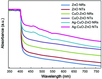 | ||
| Fig. 6 UV-Vis absorption spectra of the bare ZnO NTs and NRs, binary CuO–ZnO NTs and NRs, ternary Ag–CuO–ZnO NTs and NRs. | ||
| Materials | BET surface areaa (m2 g−1) | Single point total pore volumeb (cm3 g−1) | Average pore diameterc (nm) |
|---|---|---|---|
| a The BET surface area is achieved from the linear part of the BET graph. b The total pore volume of the pores (P/P0 = 0.99). c The average adsorption pore width (4 V A−1 by BET).23 | |||
| Ag–CuO–ZnO NTs | 19.85 | 0.35 | 14.57 |
| Ag–CuO–ZnO NRs | 1.77 | 0.01 | 7.04 |
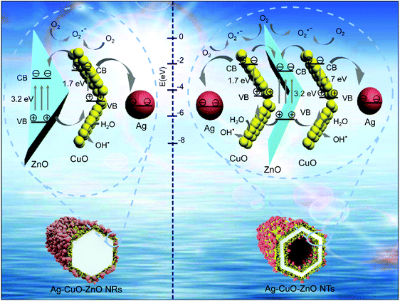
The proposed mechanisms of the intensive photodegradation efficiency for the ternary Ag–CuO–ZnO NTs are illustrated in Fig. 7. Different from the ternary Ag–CuO–ZnO NRs, photocatalytic reactions of which only take place at the outer surface, those on the ternary Ag–CuO–ZnO NTs are able to occur simultaneously on the inner and outer surfaces. Under visible light irradiation, the photocatalytic processes involve two steps, which principally depend on the charge transfer reactions to create radical species for the decomposition of pollutants. To be specific, owing to the narrow bandgap of CuO, electrons are stimulated by visible light and transferred from the valance band (VB) of CuO to the conduction band (CB), while the holes are retained in the VB.31 Then, ZnO is employed as a photoelectronic acceptor along with the photo-generated electrons in the CB of CuO being promptly propagated to the CB of ZnO. The photo-induced electrons can be captured by oxygen, allowing the formation of superoxide radical anions (O2 + e− → O2˙−). This results in the removal of organic pollutants in the sewage or further produces oxygen species via various reactions with H+. Simultaneously, the holes transfer in the reverse direction, which can oxidize H2O into hydroxyl radicals (H2O + h+ → OH˙). Such highly oxidized hydroxyl radicals have chemical reactions with organic species to primarily generate CO2 as well as H2O (step 1).48
When binary CuO–ZnO NTs are functionalized with Ag nanoparticles, the energy level of the CB for CuO is larger than the newly generated Fermi energy level, which is ascribed to the difference of work functions between CuO (∼5.5 eV) and Ag (∼4.3 eV).26 This results in a portion of the photogeneration of electrons being moved from CB of CuO to Ag. Then, these electrons in the Ag component can be captured by the chemisorbed O2 to form the superoxide radicals (O2˙−), leading to the reaction with organic species (step 2).27 Therefore, the optimized photocatalytic efficiency of the ternary Ag–CuO–ZnO NTs is attributed to the synergistic effect of three functional components with the vertically aligned ZnO NT array as the backbone structures.
The highly stabilized photocatalysts, without photocorrosion in aqueous solution, are of paramount importance for practical wastewater remediation. To demonstrate the photostability of the as-fabricated ternary ZnO NTs and NR-based photocatalysts, twenty successive recycling measurements for the degradation of MO are carried out (Fig. 8). It is observed that the photodegradation performance of the ternary Ag–CuO–ZnO NT composite almost remains unchanged, while the photocatalytic activity of Ag–CuO–ZnO NRs decreases dramatically from 46% to 5% after twenty recycle tests. Three possible factors are responsible for the superior photostability of ternary ZnO NT-based composites as compared to that of ternary ZnO NR-based catalysts. First, the ZnO NTs are composed of only (10–10) surfaces with the equivalent O2− and Zn2+, which have lower surface energy. However, the ZnO NRs consist of (0001)-O and (0001)-Zn planes with non-equivalent O2− and Zn2+. As the reactions of photodegradation principally involve holes (h+) and surface oxygen of ZnO, the ZnO NRs with higher surface energy are prone to be consumed by holes and thus demonstrate much weaker photocatalytic performance after more than ten recycling cycles.34 Second, the protective layer of CuO only occurs in the outer surface of Ag–CuO–ZnO NRs, while the coverage of the CuO shells appears in the inner and outer surfaces of Ag–CuO–ZnO NTs, leading to more effective protection of the surface oxygen in ZnO exposed in solution.21 Third, the more efficient propagation of holes from ZnO NTs to CuO also hinders them from attacking the surface oxygen of ZnO NTs.31
Furthermore, XRD patterns of the samples also indicate that Ag–CuO–ZnO NTs keep their crystal structures even after photocatalytic degradation for 20 cycles, while all the diffraction peaks of Ag–CuO–ZnO NRs decrease rapidly and even disappear (Fig. S11†). This phenomenon indicates that the framework of crystal structures of ZnO NRs collapses after the prolonged photodegradation, making the Ag and CuO nanoparticles dissolve in the pollutant solution. In contrast, the photocorrosion of ZnO NTs can be efficiently inhibited, which is capable of preserving the intact structures of photocatalysts after the super-long photodegradation. These results reveal that the ternary Ag–CuO–ZnO NTs exhibit perdurable and effective photocatalytic capability, which not only affords excellent potential for practical environmental remediation, but also opens up new opportunities for other applications, such as recyclable surface enhanced Raman scattering (SERS) substrates.49,50
4. Conclusions
In summary, the ternary Ag–CuO–ZnO NT composite is successfully synthesized using the oriented 1D ZnO NTs as the building block via facile chemical deposition and photochemical deposition approaches. It is found that Ag–CuO–ZnO NTs demonstrate much higher photocatalytic performance in pollutant decomposition than Ag–CuO–ZnO NRs. Such excellent performance of ZnO NT-based photocatalysts is primarily ascribed to the intensive visible light harvesting, efficient electron–hole separation and high specific surface area. Meanwhile, the Ag–CuO–ZnO NTs demonstrate ultra-stable photocatalytic performance towards pollutant degradation in comparison with Ag–CuO–ZnO NRs. This is mainly attributed to the unique intrinsic crystal structures of ZnO NTs as well as the functionalized CuO as the protective layers. This work paves a new way to construct ternary ZnO NT-based heterostructured photocatalysts with the excellent performance of superior photodegradation and photocorrosion suppression for practical sewage treatment and other potential applications.Acknowledgements
This work was funded by an A*STAR, SERC 2014 Public Sector Research Funding (PSF) grant (SERC Project No. 1421200080).Notes and references
- X. Liu, J. Iocozzia, Y. Wang, X. Cui, Y. Chen, S. Zhao, Z. Li and Z. Lin, Energy Environ. Sci., 2017, 10, 402–434 CAS.
- Z. L. Wang, Faraday Discuss., 2015, 176, 447–458 RSC.
- X. S. Meng, G. Zhu and Z. L. Wang, ACS Appl. Mater. Interfaces, 2014, 6, 8011–8016 CAS.
- T. Jiang, L. M. Zhang, X. Chen, C. B. Han, W. Tang, C. Zhang, L. Xu and Z. L. Wang, ACS Nano, 2015, 9, 12562–12572 CrossRef CAS PubMed.
- M. Q. Yang, N. Zhang, M. Pagliaro and Y. J. Xu, Chem. Soc. Rev., 2014, 43, 8240–8254 RSC.
- M. Wang, J. Ioccozia, L. Sun, C. Lin and Z. Lin, Energy Environ. Sci., 2014, 7, 2182–2202 CAS.
- N. Zhang, R. Ciriminna, M. Pagliaro and Y. J. Xu, Chem. Soc. Rev., 2014, 43, 5276–5287 RSC.
- C. F. Tan, W. L. Ong and G. W. Ho, ACS Nano, 2015, 9, 7661–7670 CrossRef CAS PubMed.
- D. Hong, W. Zang, X. Guo, Y. Fu, H. He, J. Sun, L. Xing, B. Liu and X. Xue, ACS Appl. Mater. Interfaces, 2016, 8, 21302–21314 CAS.
- N. Zhang, M. Q. Yang, S. Liu, Y. Sun and Y. J. Xu, Chem. Rev., 2015, 115, 10307–10377 CrossRef CAS PubMed.
- L. Zhu, M. Hong and G. W. Ho, Nano Energy, 2015, 11, 28–37 CrossRef CAS.
- F. X. Xiao, J. Miao, H. B. Tao, S. F. Hung, H. Y. Wang, H. B. Yang, J. Chen, R. Chen and B. Liu, Small, 2015, 11, 2115–2131 CrossRef CAS PubMed.
- Y. Wang, L. Liu, L. Xu, X. Cao, X. Li, Y. Huang, C. Meng, Z. Wang and W. Zhu, Nanoscale, 2014, 6, 6790–6797 RSC.
- D. Deng, S. T. Martin and S. Ramanathan, Nanoscale, 2010, 2, 2685–2691 RSC.
- Y. J. Liu, L. Sun, J. G. Wu, T. Fang, R. Cai and A. Wei, Mater. Sci. Eng., B, 2015, 194, 9–13 CrossRef CAS.
- Y. L. Chen, L. C. Kuo, M. L. Tseng, H. M. Chen, C. K. Chen, H. J. Huang, R. S. Liu and D. P. Tsai, Opt. Express, 2013, 21, 7240–7249 CAS.
- C. Han, Z. Chen, N. Zhang, J. C. Colmenares and Y. J. Xu, Adv. Funct. Mater., 2015, 25, 221–229 CrossRef CAS.
- J. G. Wu, T. Fang, R. Cai, S. Y. Li, Y. Wang, C. E. Zhao and A. Wei, RSC Adv., 2016, 6, 4145–4150 RSC.
- C. Tian, Q. Zhang, A. Wu, M. Jiang, Z. Liang, B. Jiang and H. Fu, Chem. Commun., 2012, 48, 2858–2860 RSC.
- A. van Dijken, E. A. Meulenkamp, D. Vanmaekelbergh and A. Meijerink, J. Phys. Chem. B, 2000, 104, 1715–1723 CrossRef CAS.
- K. M. Lee, C. W. Lai, K. S. Ngai and J. C. Juan, Water Res., 2016, 88, 428–448 CrossRef CAS PubMed.
- L. Zhu, M. Hong and G. W. Ho, Sci. Rep., 2015, 5, 11609–11619 CrossRef CAS PubMed.
- Z. Chen, N. Zhang and Y. J. Xu, CrystEngComm, 2013, 15, 3022–3030 RSC.
- Q. Deng, X. Duan, D. H. Ng, H. Tang, Y. Yang, M. Kong, Z. Wu, W. Cai and G. Wang, ACS Appl. Mater. Interfaces, 2012, 4, 6030–6037 CAS.
- N. Zhang, S. Xie, B. Weng and Y. J. Xu, J. Mater. Chem. A, 2016, 4, 18804–18814 CAS.
- Y. Sun, Y. Sun, T. Zhang, G. Chen, F. Zhang, D. Liu, W. Cai, Y. Li, X. Yang and C. Li, Nanoscale, 2016, 8, 10774–10782 RSC.
- S. T. Kochuveedu, Y. H. Jang and D. H. Kim, Chem. Soc. Rev., 2013, 42, 8467–8493 RSC.
- N. Zhang, C. Han, Y. J. Xu, J. J. Foley IV, D. Zhang, J. Codrington, S. K. Gray and Y. Sun, Nat. Photonics, 2016, 10, 473–482 CrossRef CAS.
- Y. Wang, H. B. Fang, Y. Z. Zheng, R. Ye, X. Tao and J. F. Chen, Nanoscale, 2015, 7, 19118–19128 RSC.
- C. Han, Q. Quan, H. M. Chen, Y. Sun and Y. J. Xu, Small, 2017, 13, 1602947 CrossRef PubMed.
- J. Yu, S. Zhuang, X. Xu, W. Zhu, B. Feng and J. Hu, J. Mater. Chem. A, 2015, 3, 1199–1207 CAS.
- J. Bai, Y. Li, R. Wang, K. Huang, Q. Zeng, J. Li and B. Zhou, J. Mater. Chem. A, 2015, 3, 22996–23002 CAS.
- C. Han, M. Q. Yang, B. Weng and Y. J. Xu, Phys. Chem. Chem. Phys., 2014, 16, 16891–16903 RSC.
- B. Weng, M. Q. Yang, N. Zhang and Y. J. Xu, J. Mater. Chem. A, 2014, 2, 9380–9389 CAS.
- S. Ameen, M. S. Akhtar, Y. S. Kim, O. B. Yang and H. S. Shin, Colloid Polym. Sci., 2010, 289, 415–421 Search PubMed.
- P. Y. Kuang, Y. Z. Su, K. Xiao, Z. Q. Liu, N. Li, H. J. Wang and J. Zhang, ACS Appl. Mater. Interfaces, 2015, 7, 16387–16394 CAS.
- P. Zhang, B. Li, Z. Zhao, C. Yu, C. Hu, S. Wu and J. Qiu, ACS Appl. Mater. Interfaces, 2014, 6, 8560–8566 CAS.
- D. Chu, Y. Masuda, T. Ohji and K. Kato, Langmuir, 2010, 26, 2811–2815 CrossRef CAS PubMed.
- A. Wei, X. W. Sun, C. Xu, Z. L. Dong, Y. Yang, S. T. Tan and W. Huang, Nanotechnology, 2006, 17, 1740–1744 CrossRef CAS PubMed.
- X. Qi, G. She, Y. Liu, L. Mu and W. Shi, Chem. Commun., 2012, 48, 242–244 RSC.
- G. D. Moon, J. B. Joo, I. Lee and Y. Yin, Nanoscale, 2014, 6, 12002–12008 RSC.
- J. M. Herrmann, H. Tahiri, Y. Ait-Ichou, G. Lassaletta, A. Gonzalez-Elipe and A. Fernandez, Appl. Catal., B, 1997, 13, 219–228 CrossRef CAS.
- I. Alessandri and J. R. Lombardi, Chem. Rev., 2016, 116, 14921–14981 CrossRef CAS PubMed.
- C. Chen, Y. Zheng, Y. Zhan, X. Lin, Q. Zheng and K. Wei, Dalton Trans., 2011, 40, 9566–9570 RSC.
- S. A. Ansari, M. M. Khan, M. O. Ansari, J. Lee and M. H. Cho, J. Phys. Chem. C, 2013, 117, 27023–27030 CAS.
- Y. Hong, C. Tian, B. Jiang, A. Wu, Q. Zhang, G. Tian and H. Fu, J. Mater. Chem. A, 2013, 1, 5700–5708 CAS.
- D. Liu, Y. Lv, M. Zhang, Y. Liu, Y. Zhu, R. Zong and Y. Zhu, J. Mater. Chem. A, 2014, 2, 15377–15388 CAS.
- L. Zheng, S. Han, H. Liu, P. Yu and X. Fang, Small, 2016, 12, 1527–1536 CrossRef CAS PubMed.
- K. C. Xu, C. T. Zhang, R. Zhou, R. Ji and M. H. Hong, Opt. Express, 2016, 24, 10352–10358 CrossRef CAS PubMed.
- K. C. Xu, C. T. Zhang, T. H. Lu, P. Wang, R. Zhou, R. Ji and M. H. Hong, Opto-Electron. Eng., 2017, 44, 185–191 Search PubMed.
Footnotes |
| † Electronic supplementary information (ESI) available. See DOI: 10.1039/c7nr03279j |
| ‡ These authors contributed equally to this work. |
| This journal is © The Royal Society of Chemistry 2017 |

