DOI:
10.1039/C7NH00050B
(Communication)
Nanoscale Horiz., 2017,
2, 253-260
Determination of the length and diameter of nanorods by a combination of analytical ultracentrifugation and scanning mobility particle sizer†
Received
31st March 2017
, Accepted 6th June 2017
First published on 6th June 2017
Abstract
A combination of orthogonal measurement techniques is utilized in this study to predict the average lengths and diameters of colloidal nanorods. Sedimentation coefficient distributions and electrical mobility distributions obtained from analytical ultracentrifugation and a scanning mobility particle sizer, respectively, are used for the hydrodynamic correlation. The method is validated theoretically and application to Au and ZnO nanorod samples is shown. The results demonstrate that the combination of both measurement techniques is an excellent method for the two-dimensional characterization of nanorods.
Conceptual insights
The multidimensional characterization of nanoparticle ensembles is highly relevant in nanotechnology where functionality is determined beyond size by shape, surface and morphology of the nanoparticles. Multidimensional characterization requires combining orthogonal measurement techniques providing access to several particle dimensions. Current attempts to simultaneously measure the length and diameter of colloidal nanorods in a sample are based on tedious and time-consuming image analysis. We combine measurements from analytical ultracentrifugation (AUC) in liquids with scanning mobility particle sizing (SMPS) in the gas phase to accurately measure the average length and diameter of polydisperse nanorods with high statistical significance. The unique combination of AUC and SMPS is a fast, reliable, accurate and highly reproducible method to analyze the diameter and length of nanorods. The technique has the potential to be transferred to other shapes as well.
|
Introduction
As the excellent physicochemical properties of nanoparticles (NPs), including enhanced optoelectronic properties, are often dependent on their disperse properties including size, shape and polydispersity, accurate evaluation of the disperse properties becomes a necessity. Besides size, particle shape comes into focus since tuning the particle shape opens new possibilities to tailor the resulting product properties. This has motivated the development of synthesis routes to prepare particles of various geometries.1,2
Currently available measurement techniques focus mainly on size characterization of NPs while shape characterization is mostly based on tedious image analysis. Fast and reliable techniques for the simultaneous measurement of size and shape of NP distributions are still missing. As long as the particle is spherical, the only relevant length scale is the diameter and properties measured by various analytical instruments can be easily correlated to it. However, size evaluation is complicated for non-spherical NPs where equivalent size parameters such as the volume equivalent sphere diameter, Sauter diameter, sedimentation equivalent sphere diameter or mobility equivalent sphere diameter are used to represent the particle size. For obtaining information on the geometric shape parameters of non-spherical NPs, parallel measurements by multiple instruments are often required. Hence, data need to be simultaneously analyzed to relate it to the relevant geometric length scales.3–5
Nanorods (NRs) are commonly used non-spherical NPs which require two parameters (length and diameter) for complete size and shape characterization. Semiconductor and metal NRs have attracted considerable attention in the recent past mainly in electronics, photonics and drug delivery related applications. Gold (Au) NRs are quite promising due to their enhanced optical properties arising from plasmon resonance effects.2,6,7 Semiconductor nanostructures have gained attraction due to the possibility of applications in electronics and life science.8 Zinc oxide (ZnO) NRs are of particular relevance as they have been incorporated in a number of nanodevices, including sensors, field effect transistors, light emitting device arrays, as well as in thin film applications.9
Even though electron microscopy based methods are the most obvious and commonly used techniques for characterizing non-spherical NPs, there is the inherent drawback that these methods require analysis of a large number of particles for sufficient statistics. They are also time intensive methods, sample preparation may be difficult and the irradiation of high energy electron beams could affect the particle morphology and dimensions. Dynamic light scattering (DLS) is also commonly used to measure the hydrodynamic diameter of NRs in suspensions mainly due to its simplicity.9–14 However, this technique is complicated for non-spherical particles due to the effect of rotational diffusion and the hydrodynamic size measured is different from the actual values. Efforts have been made to use depolarized dynamic light scattering (DDLS) to gather information on the translational and rotational diffusion coefficients of NRs and to relate this to their diameter and length.10 Although the technique sounds promising, studies have shown that the errors involved during the retrieval of the two geometric descriptors are not negligible while using DDLS. It has been shown that a combination of DLS and DDLS can be used for the investigation of rigid rods but it is important to use other complementary techniques in parallel as well.14
Analytical ultracentrifugation (AUC) is considered to be the gold standard for characterizing NPs, polymers and biomolecules.15–20 With considerable developments in the recent past including the development of multiwavelength detectors, AUC has been used for measuring sizes, densities and optical properties of NPs.21–23 Sedimentation coefficient distributions of the NPs are obtained from centrifugation experiments and can be, with relevant information, easily converted to obtain size distributions of spherical NPs. For non-spherical NPs, the sedimentation coefficient depends on the particle mass as well as the hydrodynamic diameter.19 AUC has been used in the recent past for characterizing NRs and platelets where background information on the shapes were already available.19,24,25 Alternatively, diffusional broadening in sedimentation experiments can be utilized for slowly settling systems to derive information on shape anisotropy. However, this procedure requires the diffusion information to be sufficiently represented in the data. This is feasible for most synthetic polymers and biological systems in the size range below a few 10 nm but cannot be ensured when dealing with the majority of metal or semiconductor NRs because of their high density and fast sedimentation rates.
Transferring the colloidal NPs to be dispersed in the gas phase opens up new possibilities for measuring the particle properties. Compared to colloidal NPs, transport properties involving aerosol NPs cannot always be defined by the continuum regime owing to the typical sizes being in the range as the background gas mean free path.26 For aerosol particles, the most commonly used analytical instrument is the scanning mobility particle sizer (SMPS) that classifies particles based on their electrical mobility.27 The electrical mobility of particles can be converted to their friction factor/diffusion coefficient which in turn depends on their geometric parameters including the hydrodynamic diameter. Sedimentation coefficient and electrical mobility, both being dependent on the geometric aspects of the NPs, can therefore be combined to predict the relevant length parameters of non-spherical particles. It was shown that for Au NRs, mobilities and volume can be measured by combining electrospray–SMPS with and without the presence of an electric furnace.28 Various attempts have been made to combine measurement techniques for characterization of non-spherical NPs, particularly fractal aggregates. A combination of SMPS and aerosol particle mass analyzer (APM) is commonly used to study the size and density of NPs.29–31 Mass mobility relationships are used to study shape factors of non-spherical particles as well and with specific retrieval techniques, this method can in principle be extended for 2-dimensional characterization of NRs.32–34
In this study, we combine the data from sedimentation coefficients in liquids and electrical mobility measurements in gases. First, the methodology is validated by means of theoretical data. Then, it is shown for experimental data of Au and ZnO NRs that it is possible to measure mean values of length and diameter. Results are further confirmed by means of transmission electron microscopy (TEM) and scanning electron microscopy (SEM) data. To the best of our knowledge, this is the first successful attempt at accurately characterizing the length and diameter of NRs in a given sample by combining these orthogonal experimental techniques.
Theory
Analytical ultracentrifugation
The sedimentation velocity (SV) experiment is the most commonly used method for NP characterization via AUC. The motion of the concentration boundaries is measured in situ using optical detectors as a function of time and space. The boundaries contain information on the sedimentation and diffusion coefficient distributions. For samples exhibiting negligible diffusion such as the NRs investigated in this study, the sedimentation coefficient distributions can be easily derived by means of a least-squares direct boundary modelling approach, originally developed by Schuck and Rossmanith.35
The Svedberg equation relates the sedimentation and diffusion coefficient with the molar mass of the analyte:
| | 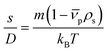 | (1) |
In this equation, s denotes the sedimentation coefficient, D the diffusion coefficient, m the mass and  the partial specific volume of the sedimenting particle. ρs is the solvent's density, kB the Boltzmann constant and T the temperature in Kelvin. While s can be directly obtained from the AUC experiment, D is given by the extended Stokes–Einstein's law as:
| |  | (2) |
η is the viscosity of the solvent,
xh is the particle's hydrodynamic diameter. The mass of a rod is given by:
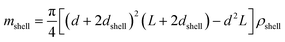
| |  | (3) |
d are
L are the diameter and length of the NR, respectively.
Eqn (2) and (3) can be inserted into Svedberg's equation finally providing:
| | 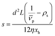 | (4) |
For application of this correlation, it has to be taken into account that the stabilizing shell around the NP alters its sedimentation properties. The overall effect depends on the size and density of the stabilizing layer and can be accounted for
via a core–shell model analogous to a recent study on spherical NPs.
36Eqn (4) can be rewritten as follows:
| | 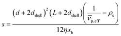 | (5) |
dshell is the thickness of the stabilizing layer and

is the effective partial specific volume, which is the inverse of the density of the solvated NR including its shell.

is given by:
| | 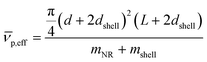 | (6) |
mNR and
mshell are the masses of the pure NR and shell, respectively.
mNR is given
viaeqn (3), while the latter quantity can be calculated as follows:
| |  | (7) |
ρshell is the density of the stabilizing layer taking the solvation effects into account.
The SV experiment provides s, while the particle and solvent parameters have to be known. Moreover, an orthogonal measurement technique is required to measure xh. In principle, 2-dimensional analyses of AUC data as implemented in Sedfit37 or UltraScan338 would allow for the simultaneous determination of the sedimentation and diffusion coefficients. The diffusion coefficient can then be linked to xh. Such type of analysis was checked but discarded as the sedimentation transport exceeded the diffusional transport significantly for all systems investigated. dshell and ρshell can be determined in a correlation study using TEM or SEM for example, analogous to our investigation of graphene oxide nanoplatelets.25
Scanning mobility particle sizer
Electrical mobility measurements with differential mobility analyzers (DMA) are still widely used for characterizing NPs dispersed in the gas phase.27,39 DMA in combination with a counting instrument (often a condensation particle counter) is referred to as SMPS and can be combined to provide a continuous fast scanning technique to measure the electrical mobility distribution of aerosol NPs.40 The scalar electrical mobility (B) can be related to the scalar friction factor (f) via:| |  | (8) |
n is the number of elementary charges e on the particle. The friction factor of particles, which is a representation of the drag force on the particles, is an important parameter as drag forces control the motion of NPs in gas phase environments. To completely characterize the friction factor of NPs, two size descriptors are required: the hydrodynamic diameter (xh) and the orientationally averaged Projected Area (PA). With the knowledge of these parameters, the drag on a non-spherical particle can be given as an extension of the Stokes' law which accounts for non-continuum effects:| |  | (9a) |
| |  | (9b) |
| |  | (9c) |
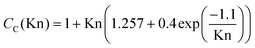
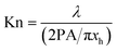
η is the background fluid viscosity, λ is the background fluid mean free path and CC is the Cunningham correction factor. The expression for Cunningham correction factor as given in eqn (9b) is valid for measurements in air and the constants need to be changed for measurements in different gases.41 Kn is the momentum transfer Knudsen number and is an indicator of the regime in which the momentum transfer process is happening. Kn ≪ 1 represents the continuum regime while Kn ≫ 1 represents the free molecular regime for momentum transfer processes. In colloidal systems, momentum transfer happens purely in the continuum regime and the xh of the particle alone is required to describe the friction factor as described by the Stokes' law with CC(Kn) → 1 (in eqn (9a)) as the value of Kn is practically 0. For most NPs dispersed in gas phase systems, the value of Kn is closer to 1, where the momentum transfer process happens to be in the intermediate region termed as the transition regime. The ratio PA/πxh is essential for determining the momentum transfer regime and the factor 4PA/πxh2 is an indicator of the shape anisotropy of the particle, with the ratio closer to 1 representative of a near spherical shape of the particle. It is relevant for our calculations that the mobility of NPs in the transition regime inherently has information of two geometric descriptors, namely xh and PA, which are independent of the background fluid and experimental conditions. The equations simplify for spherical NPs where they are functions of only the particle diameter, and the mobility distribution can be easily converted to a PSD. For given shapes and sizes, xh and PA can be calculated quite accurately and quickly by different algorithms.42 The validity of using the method for characterizing rod shaped particles has been demonstrated by Gopalakrishnan et al. by combining mobility analysis with images obtained from TEM.43 This model was also used to study the mobility analysis of flame generated NP aggregates in order to recreate 3D images of NP aggregates from 2D TEM images.44
Methods
Au NR preparation
Three samples of Au NRs were purchased from nanoComposix and were measured using AUC and SMPS for the experimental verification of the proposed method. NR samples were stabilized with citrate using a 2 mM citrate buffer. Owing to the difference in aspect ratios of the rods, the plasmon resonant peaks for the three samples are at 660 nm, 800 nm and 980 nm, respectively. Size statistics, average dimensions and corresponding standard deviations of the NRs were provided by the manufacturer based on TEM measurements recorded using a JEOL 1010 TEM. The three Au samples are referred to as samples #1, #2 and #3 in the subsequent sections. The average lengths of NR samples #1, #2 and #3 are 45.5 (±6.3) nm, 58.4 (±4.4) nm and 69.3 (±10.1) nm, respectively, while the average diameters are 17.4 (±1.2) nm, 15.4 (±1.4) nm and 12.0 (±0.8) nm, respectively. The aspect ratio of the NRs increases from sample #1 to #3, resulting in the shift of the plasmon resonance peak.
ZnO NR preparation
ZnO NRs were prepared in methanol by precipitation from solutions of zinc acetate dihydrate (ZnAc2·2H2O) and potassium hydroxide (KOH). The KOH solution (1.4 mol L−1) was dropped within 10 min to the ZnAc2·2H2O solution (0.71 mol L−1). ZnO NRs were formed by subsequent refluxing at 75 °C. The diameter of the NRs is relatively constant compared to their length which increases in general over the refluxing time. The synthesis was stopped by cooling down and washing the NRs twice with fresh methanol to get rid of residues. For primary particle stabilization, the NRs were washed four times in ethanol and were dispersed by subsequent addition of [2-(2-(2-methoxyethoxy)ethoxy)acetic acid] (TODA). Two samples with refluxing times of 12 h and 120 h were chosen for the study. These are referred to as samples #4 and #5 in the rest of the manuscript.
Analytical ultracentrifugation
SV data was acquired using a modified preparative ultracentrifuge from Beckman Coulter, type Optima L-90K, with an integrated UV-Vis MWL detector. The optical path length of the titanium centerpieces from Nanolytics was 12 mm. SV data was acquired for all systems at a radial step size of 50 μm and temperature of 20 °C. All samples were measured as received without further purification. For the Au NRs, the rotor speed was 3500 rpm (sample #1) and 3000 rpm (samples #2 and #3). ZnO NRs were measured at 3000 rpm (sample #4) and 4000 rpm (sample #5). Extinction data at 520 nm (Au NRs) and 300 nm (ZnO NRs) was fitted to the least-square direct boundary distribution model ls-g*(s) using Sedfit (v. 14.81).
Scanning mobility particle sizer
Mobility spectra for the NRs were obtained using a TSI 3080 series electrostatic classifier equipped with a combination of nano DMA (model 3085) and ultrafine CPC (model 3776). Au NRs were transferred to gas phase using electrospray atomization while ZnO NRs were transferred to be dispersed in gas phase by atomization using a Laskin atomizer. Au samples were washed with 15 mM Ammonuim acetate solution before electrospraying. ZnO samples were used as prepared and a dilution series was carried with ethanol to ensure the measurements were in the dilute limit. Measurements were taken as average of at least five different runs for the same sample.
Results and discussion
Analysis concept
A retrieval algorithm was developed to obtain the mean length and diameter of NRs in a sample by utilizing the measured sedimentation coefficient and mobility diameter distributions which are obtained from AUC and SMPS measurements, respectively. The mobility diameter is defined as the diameter of the sphere having the same mobility as the particle under consideration. Mean values of sedimentation coefficient and mobility diameter obtained from the measurements are input to the algorithm and a search is done over a 2D space of length and diameter of NRs. For each combination of length and diameter, a corresponding sedimentation coefficient and mobility diameter is calculated based on the xh and PA values. xh values are determined using the expression provided by Hansen45 while PA of the NRs are calculated using Cauchy's rule according to which the PA of a convex shaped object is one fourth of its total surface area. In the case of non-spherical concave shaped particles, Monte Carlo methods can be used to obtain the corresponding PA values.46 For each combination of the NR length and diameter, the algorithm assigns an error which is the sum of the normalized differences of the theoretically calculated sedimentation coefficient and mobility diameter values compared to the measured values input to the algorithm. Objective of the algorithm is to find the specific combination of the length and diameter for which the calculated error is minimal.
To ensure that well-posedness of the retrieval, theoretically calculated values of sedimentation coefficient and electrical mobility for Au NRs of length 65 nm and diameter 10 nm were used to test the algorithm.
For the retrieval, the diameter was varied between 1 nm and 100 nm in increments of 0.1 nm while the aspect ratio was varied from 1 to 50. The retrieval algorithm predicted a global minimum for the calculated error as represented in Fig. 1. It is important to note that the global minimum is well confined and the error is sufficiently different from all other parameter combinations. This allows us to identify the correct mean diameter and aspect ratio of the NR. For the given case, the predicted length and diameter values are 65.0 nm and 10.0 nm, respectively, which is in perfect agreement with the simulated data.
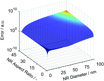 |
| | Fig. 1 Error calculated for different combinations of NR length and diameter compared to the input values of sedimentation coefficient and mobility diameter. | |
Investigation of Au and ZnO NRs
The algorithm was then applied to measurements for Au and ZnO NRs. Fig. 2(a)–(c) show TEM images of the purchased gold NRs (provided by nanoComposix) while Fig. 2(d)–(e) depict SEM images of samples #4 and #5 deposited on a solid substrate. A closer look at the NRs reveals hemispherical ends for both Au and ZnO NRs as opposed to flat, circular ends normally expected for cylindrical NRs. It has been shown before that the hemispherical caps have negligible influence on the values of PA and xh compared to cylindrical NRs.43 However, it has a significant influence on the sedimentation coefficient calculation by virtue of its effect on particle mass. Eqn (3)–(7) were modified accordingly to take into consideration the effect of the hemispherical end caps.
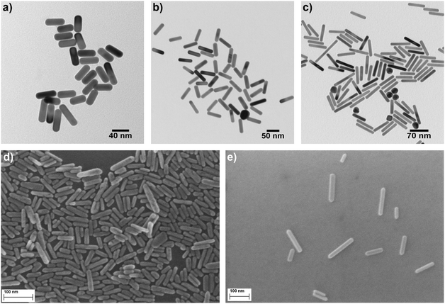 |
| | Fig. 2 TEM images of Au NR sample (a) #1, (b) #2 and (c) #3. SEM images of ZnO NR sample (d) #4 and (e) #5. It is apparent that all NRs have hemispherical end caps. | |
As explained in the methods section, quantifying the effect of stabilizing layer around the particles is also necessary for accurate AUC analysis. TEM (Au NRs) or SEM (ZnO NRs) statistics were used as a benchmark for an approximation of the shell thickness. The effect of the stabilizer molecules is expected to have more impact in the case of metal NPs with high bulk mass densities. Au NRs were chosen to test the validity of the proposed method where the effect of the stabilizer shell has a high impact, especially on the AUC experiments. Comparisons of TEM obtained values and fitting AUC and SMPS data for sample #1 showed that the stabilizer molecules have an effect on both the measurements. While a shell thickness of 1.2 nm fits well for the data obtained from SMPS measurement, the thickness was found to be 4.0 nm for the AUC measurement when assuming its density to be in between the solvent and citrate density. These values were also found reasonable in the case of other samples and are used for all subsequent calculations involving Au NRs. For ZnO NRs, it was found that for a shell thickness of 2 nm, while assuming that the shell density is equal to the solvent density, the theoretically calculated sedimentation coefficient distribution closely matches the distribution obtained from the centrifugation experiment. In contrast, the stabilizer molecules seemed to have negligible effect on the mobility measurements for ZnO NRs. It is important to note that these values need not necessarily represent the actual thickness of the stabilizer molecules around the NRs, but they represent an overall impact of the stabilizer molecules in altering the properties of the particles and will in case of AUC also include effects due to adsorbed solvent molecules and double layer formation. Consequently, the shell thickness is more significant and prominent for AUC measurements due to the effect of the loosely bound stabilizer molecules and the adsorbed solvent molecules to the NP surface. The thickness depends on the NP material and the type of stabilizer. Thus, it needs to be fitted once for each combination of NR and stabilizer before utilizing the retrieval method for determining the dimensions of the NRs.
Fig. 3(a) compares the theoretically calculated sedimentation coefficient distribution based on TEM image analysis of Au NRs with the data obtained from AUC experiment for sample #1. Although the distribution of monomers seem quite monodisperse, the presence of dimers and larger aggregates is visible in the plot. Fig. 4(a) compares the sedimentation coefficient distributions obtained by the theoretical prediction using SEM images and the data obtained from centrifugation experiment for the case of ZnO sample #4. The longer tail of the experimentally obtained distribution is possibly due to the presence of a few aggregated particles. Comparison of the normalized mobility diameter distribution of samples #1 and #4 obtained from SMPS measurements, and the theoretically obtained expected distributions are provided in Fig. 3(b) and 4(b), respectively. The larger width of the distribution for the measured distribution for ZnO NRs can be attributed to slight effects of particle diffusion and the presence of aggregated particles leading to the longer tail of the distribution. There is also another peak for lower mobility diameters (not shown in the figures) owing to the presence of residues and is present in all atomizer-SMPS measurements. It is necessary that the peak of the distribution of the NPs can be distinguished from the peak of the residue distribution for accurate analysis. The distributions obtained from AUC and SMPS measurements were then fitted with log-normal distributions as shown in Fig. 3 and 4 to solely account for the main NR species in the subsequent analysis. Mean values of sedimentation coefficients and mobility diameters obtained from the fitted distributions were then input to the retrieval algorithm. The algorithm calculated theoretical values of sedimentation coefficient and mobility diameter corresponding to different combinations of length and diameter of NRs with hemispherical end caps and the corresponding shell thicknesses. The output from the retrieval algorithm was average values of NR length and diameter for which the error between the input mean values and the theoretical values of sedimentation coefficient and mobility diameter were minimal.
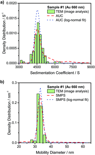 |
| | Fig. 3 Analysis results for Au NR sample #1. (a) Expected sedimentation coefficient distribution obtained from theoretical calculations from TEM image analysis, from AUC measurements and the log-normal distribution fit to the AUC data. (b) Expected mobility diameter obtained from theoretical calculations based on TEM image analysis, from SMPS measurements and the log-normal distribution fit to the SMPS data. | |
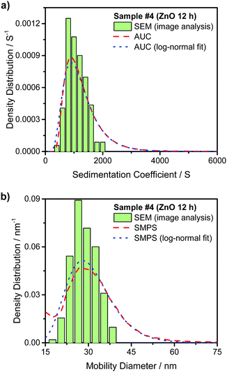 |
| | Fig. 4 Analysis results for ZnO NR sample #4. (a) Sedimentation coefficient distribution obtained from theoretical calculations from SEM image analysis, from AUC measurements and the log-normal distribution fit to the AUC data. (b) Normalized mobility diameter distributions obtained from theoretical calculations based on SEM image analysis, from SMPS measurements and the log-normal distribution fit to the SMPS data. | |
Experimental data obtained for the other Au and ZnO samples are provided in Fig. S1–S6 in the ESI.† The average representative values of length and diameter of the NRs obtained by this method are provided in Table 1. The dimensions for the Au NRs based on TEM images and the ZnO NRs obtained from SEM images are given for comparison along with the respective standard deviations. More than 200 images were analyzed for each of the samples of ZnO NRs in order to obtain good statistics for the SEM based analysis. The data provided by nanoComposix based on the TEM image analysis for the Au NR samples were calculated after analyzing at least 100 NRs for each of the samples. From the table it is clear that this method can be used to obtain accurate values to represent the length and diameter of NRs in a sample by combining measurements from AUC and SMPS. Despite the relatively high polydispersity in the NR length, the method provides excellent results as the deviations in both length and diameter are below 10% for the samples used in the study.
Table 1 Comparison of the non-solvated length and diameter of the NRs obtained from analysis of TEM/SEM images and the values retrieved by the method proposed in this study
| NR sample |
d
SEM/TEM/nm |
L
SEM/TEM/nm |
d
retrieved/nm |
L
retrieved/nm |
| #1 (Au) |
17.4 ± 1.2 |
45.5 ± 6.3 |
17.6 |
43.5 |
| #2 (Au) |
15.4 ± 1.4 |
58.4 ± 4.4 |
15.4 |
60.7 |
| #3 (Au) |
12.0 ± 0.8 |
69.3 ± 10.1 |
11.3 |
76.3 |
| #4 (ZnO) |
14.9 ± 2.15 |
55.2 ± 11.0 |
14.7 |
58.1 |
| #5 (ZnO) |
25.3 ± 3.94 |
131.6 ± 44.68 |
22.8 |
130.4 |
The different weighting of the distributions obtained from the two techniques has not been incorporated in the current study. For highly polydisperse systems, this could have a non-negligible effect on the accuracy of the algorithm. For fully incorporating this effect, iterative solutions are required. The assumption of using the xh and PA values for mobility analysis is strictly valid only in the cases where the NRs do not have a preferential orientation on passing through the DMA. Preferential orientation can happen in the case of very high aspect ratio NRs.47
Conclusions
In this study we have shown that centrifugation in the liquid phase and mobility measurements in the gas phase can be combined to accurately predict mean representative values of length and diameter of NRs even in polydisperse samples. The proposed method was validated for Au and ZnO NR samples with different sizes and aspect ratios. The combination of these measurements opens up many possibilities for the characterization of NPs. For example, both methods were employed to analyze the size and molar mass of soft matter particles (perfluorosulfonic acid ionomers) in dilute aqueous suspensions and these results will be reported in a forthcoming publication. Our approach provides a sound basis for obtaining the diameter and length distributions of the NRs in the samples, for which research is currently underway. Moreover, this retrieval method in combination with the algorithms for obtaining the hydrodynamic diameter xh and the orientationally averaged projected area PA can be easily extended to other 2-dimensional NP systems like platelets or ellipsoids.
Acknowledgements
The authors acknowledge the funding of the Deutsche Forschungsgemeinschaft (DFG) through the Cluster of Excellence “Engineering of Advanced Materials”. TT acknowledges the fellowship from the Alexander von Humboldt foundation. J. W. and W. P. thank the DFG for financial support through project PE 427/28-2. The authors thank Bettina Winzer for the SEM images of ZnO NRs and nanoComposix for providing the details of TEM analysis of Au NRs.
References
- M. A. El-Sayed, Acc. Chem. Res., 2004, 37(5), 326–333 CrossRef CAS PubMed.
- C. J. Murphy, T. K. Sau, A. M. Gole, C. J. Orendorff, J. Gao, L. Gou, S. E. Hunyadi and T. Li, J. Phys. Chem. B, 2005, 109(29), 13857–13870 CrossRef CAS PubMed.
- S. Jeon, T. Thajudeen and C. J. Hogan, Powder Technol., 2015, 272, 75–84 CrossRef CAS.
- S. Y. Lee, W. Widiyastuti, N. Tajima, F. Iskandar and K. Okuyama, Aerosol Sci. Technol., 2009, 43(2), 136–144 CrossRef CAS.
- Y. Yao, S. Luo and T. Liu, Macromolecules, 2014, 47(9), 3093–3100 CrossRef CAS.
- X. Huang, S. Neretina and M. A. El-Sayed, Adv. Mater., 2009, 21(48), 4880–4910 CrossRef CAS PubMed.
- P. K. Jain, X. Huang, I. H. El-Sayed and M. A. El-Sayed, Acc. Chem. Res., 2008, 41(12), 1578–1586 CrossRef CAS PubMed.
- L. Carbone, C. Nobile, M. de Giorgi, F. Della Sala, G. Morello, P. Pompa, M. Hytch, E. Snoeck, A. Fiore, I. R. Franchini, M. Nadasan, A. F. Silvestre, L. Chiodo, S. Kudera, R. Cingolani, R. Krahne and L. Manna, Nano Lett., 2007, 7(10), 2942–2950 CrossRef CAS PubMed.
- G.-C. Yi, C. Wang and W. Il Park, Semicond. Sci. Technol., 2005, 20(4), S22 CrossRef CAS.
- M. Glidden and M. Muschol, J. Phys. Chem. C, 2012, 116(14), 8128–8137 CAS.
- H. Liu, N. Pierre-Pierre and Q. Huo, Gold Bull., 2012, 45(4), 187–195 CrossRef CAS.
- T. Liu and Z. Xiao, Macromol. Chem. Phys., 2012, 213(16), 1697–1705 CrossRef CAS.
- J. Rodríguez-Fernández, J. Pérez-Juste, L. M. Liz-Marzán and P. R. Lang, J. Phys. Chem. C, 2007, 111(13), 5020–5025 Search PubMed.
- D. Lehner, H. Lindner and O. Glatter, Langmuir, 2000, 16(4), 1689–1695 CrossRef CAS.
- R. P. Carney, J. Y. Kim, H. Qian, R. Jin, H. Mehenni, F. Stellacci and O. M. Bakr, Nat. Commun., 2011, 2, 335 CrossRef PubMed.
-
J. L. Cole, J. W. Lary, T. P. Moody and T. M. Laue in Methods in Cell Biology Biophysical Tools for Biologists: Vol. 1 In VitroTechniques, ed. J. J. Correia and H. W. Detrich, III, Academic Press, London, UK, 2008, p. 143 Search PubMed.
-
Methods in Cell Biology Biophysical Tools for Biologists: Vol. 1 In VitroTechniques, ed. J. J. Correia and H. W. Detrich, III, Academic Press, London, UK, 2008 Search PubMed.
- P. Schuck, Biophys. J., 2000, 78(3), 1606–1619 CrossRef CAS PubMed.
- J. Walter, K. Löhr, E. Karabudak, W. Reis, J. Mikhael, W. Peukert, W. Wohlleben and H. Cölfen, ACS Nano, 2014, 8(9), 8871–8886 CrossRef CAS PubMed.
- K. L. Planken and H. Colfen, Nanoscale, 2010, 2(10), 1849–1869 RSC.
- E. Karabudak, E. Brookes, V. Lesnyak, N. Gaponik, A. Eychmüller, J. Walter, D. Segets, W. Peukert, W. Wohlleben, B. Demelerand and H. Cölfen, Angew. Chem., Int. Ed., 2016, 55(16), 11770–11774 CrossRef CAS PubMed.
- J. Walter and W. Peukert, Nanoscale, 2016, 8(14), 7484–7495 RSC.
- J. Walter, P. J. Sherwood, W. Lin, D. Segets, W. F. Stafford and W. Peukert, Anal. Chem., 2015, 87(6), 3396–3403 CrossRef CAS PubMed.
- J. A. Fagan, M. Zheng, V. Rastogi, J. R. Simpson, C. Y. Khripin, C. A. Silvera Batista and A. R. Hight Walker, ACS Nano, 2013, 7(4), 3373–3387 CrossRef CAS PubMed.
- J. Walter, T. J. Nacken, C. Damm, T. Thajudeen, S. Eigler and W. Peukert, Small, 2015, 11(7), 814–825 CrossRef CAS PubMed.
- B. E. Dahneke, J. Aerosol Sci., 1973, 4(2), 163–170 CrossRef.
- E. O. Knutson and K. T. Whitby, J. Aerosol Sci., 1975, 6(6), 443–451 CrossRef.
- D. K. Song, I. W. Lenggoro, Y. Hayashi, K. Okuyama and S. S. Kim, Langmuir, 2005, 21(23), 10375–10382 CrossRef CAS PubMed.
- Q. G. J. Malloy, S. Nakao, L. Qi, R. Austin, C. Stothers, H. Hagino and D. R. Cocker, Aerosol Sci. Technol., 2009, 43(7), 673–678 CrossRef CAS.
- K. Park, F. Cao, D. B. Kittelson and P. H. McMurry, Environ. Sci. Technol., 2003, 37(3), 577–583 CrossRef CAS PubMed.
- J. Beranek, D. Imre and A. Zelenyuk, Anal. Chem., 2012, 84(3), 1459–1465 CrossRef CAS PubMed.
- D. Broßell, M. Valenti, S. Bezantakos, A. Schmidt-Ott and G. Biskos, Aerosol Sci. Technol., 2015, 49(7), 495–507 CrossRef.
- M. I. Gini, C. Helmis, A. D. Melas, D. Papanastasiou, G. Orfanopoulos, K. P. Giannakopoulos, Y. Drossinos and K. Eleftheriadis, Aerosol Sci. Technol., 2016, 50(2), 133–147 CrossRef CAS.
- V. K. Rawat, D. T. Buckley, S. Kimoto, M.-H. Lee, N. Fukushima and C. J. Hogan Jr., J. Aerosol Sci., 2016, 92, 70–82 CrossRef CAS.
- P. Schuck and P. Rossmanith, Biopolymers, 2000, 54(5), 328–341 CrossRef CAS PubMed.
- J. Walter, G. Gorbet, T. Akdas, D. Segets, B. Demeler and W. Peukert, Analyst, 2017, 142(1), 206–217 RSC.
- P. H. Brown and P. Schuck, Biophys. J., 2006, 90(12), 4651–4661 CrossRef CAS PubMed.
- E. Brookes, W. Cao and B. Demeler, Eur. Biophys. J., 2010, 39(3), 405–414 CrossRef PubMed.
- K. Park, D. Dutcher, M. Emery, J. Pagels, H. Sakurai, J. Scheckman, S. Qian, M. R. Stolzenburg, X. Wang, J. Yang and P. H. McMurry, Aerosol Sci. Technol., 2008, 42(10), 801–816 CrossRef CAS.
- S. C. Wang and R. C. Flagan, Aerosol Sci. Technol., 1990, 13(2), 230–240 CrossRef CAS.
- C. N. Davies, Proc. Phys. Soc., 1945, 57(4), 259 CrossRef.
- C. Zhang, T. Thajudeen, C. Larriba, T. E. Schwartzentruber and C. J. Hogan Jr., Aerosol Sci. Technol., 2012, 46(10), 1065–1078 CrossRef CAS.
- R. Gopalakrishnan, P. H. McMurry and C. J. Hogan Jr., J. Aerosol Sci., 2015, 82, 24–39 CrossRef CAS.
- T. Thajudeen, S. Jeon and C. J. Hogan Jr., J. Aerosol Sci., 2015, 80, 45–57 CrossRef CAS.
- S. Hansen, J. Chem. Phys., 2004, 121(18), 9111–9115 CrossRef CAS PubMed.
- R. Gopalakrishnan, T. Thajudeen and C. J. Hogan Jr., J. Chem. Phys., 2011, 135(5), 54302 CrossRef PubMed.
- M. Li, R. You, G. W. Mulholland and M. R. Zachariah, Aerosol Sci. Technol., 2013, 47(10), 1101–1107 CrossRef CAS.
Footnote |
| † Electronic supplementary information (ESI) available. See DOI: 10.1039/c7nh00050b |
|
| This journal is © The Royal Society of Chemistry 2017 |

 *ab,
J.
Walter
*ab,
J.
Walter

 the partial specific volume of the sedimenting particle. ρs is the solvent's density, kB the Boltzmann constant and T the temperature in Kelvin. While s can be directly obtained from the AUC experiment, D is given by the extended Stokes–Einstein's law as:


 is the effective partial specific volume, which is the inverse of the density of the solvated NR including its shell.
  is given by:


