 Open Access Article
Device and programming abstractions for spatiotemporal control of active micro-particle swarms†‡
Amy T.
Lam
,
Karina G.
Samuel-Gama
,
Jonathan
Griffin
,
Matthew
Loeun
,
Lukas C.
Gerber
,
Zahid
Hossain
,
Nate J.
Cira
,
Seung Ah
Lee
and
Ingmar H.
Riedel-Kruse
 *
*
Stanford University, 318 Campus Drive, Clark Center Room E350A, Stanford, CA 94305, USA. E-mail: ingmar@stanford.edu
First published on 16th March 2017
Abstract
We present a hardware setup and a set of executable commands for spatiotemporal programming and interactive control of a swarm of self-propelled microscopic agents inside a microfluidic chip. In particular, local and global spatiotemporal light stimuli are used to direct the motion of ensembles of Euglena gracilis, a unicellular phototactic organism. We develop three levels of programming abstractions (stimulus space, swarm space, and system space) to create a scripting language for directing swarms. We then implement a multi-level proof-of-concept biotic game using these commands to demonstrate their utility. These device and programming concepts will enhance our capabilities for manipulating natural and synthetic swarms, with future applications for on-chip processing, diagnostics, education, and research on collective behaviors.
Introduction
Swarms of active microscopic agents have many potential applications in in situ biomedical and environmental diagnostics as well as on-chip transport and signal transduction.1–9 Controlled swarm motion may be employed to generate flows in lab-on-chip devices in conjunction with digital microfluidics,1–5,10–12 on-chip computation as previously explored with droplet logic and neural computation,7,13 cargo delivery,6,14–16 and for self-assembly of nano- and microdevices.8,10,15,17–20 Algorithms for efficient control and programming of such swarms have been extensively studied via theory20,21 and experiment in both synthetic22 and natural systems, from motor proteins and filaments23,24 to single-celled organisms2,8,25,26 to insects27 to macroscopic robots.20,21,28 For microbiological swarms, “interactive biology” setups have enabled both professionals and non-experts to interact and experiment with swarm agents in real-time for research and edutainment purposes, e.g., through biology cloud experimentation laboratories,29,30 museum exhibits,31 or biotic games.32,33,38While most of these platforms had been developed ground-up to support a single application, more expressive, general purpose setups with a larger degree of programmability are desirable for applications involving swarm control of microscopic agents. For example, some setups use global stimuli (e.g. magnetic or light fields) to control directionality of many agents, but this precludes local control over subgroups of agents.1,27,30,34–36 Other setups capitalize on local stimuli (e.g. projection of images31,37) to control individual agents at different locations, but this does not allow for directional control over these agents.20,21 Because of the limitations and agent-specific nature of these stimulus–response sets, it is often difficult to build generalizable swarm commands and algorithms that enable versatile programming of swarm behaviours.
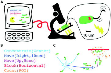
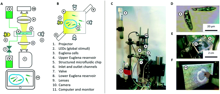
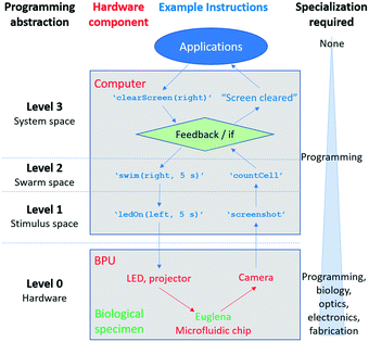
Here, we conceptualize a new hardware architecture and its associated programming abstractions for the manipulation of active micro-particle swarms inside microfluidic chips (Fig. 1). We combined several existing biotic processing units (BPUs30,38) from other experimental7,37 and interactive biology31,39 setups to create a single highly expressive BPU (Fig. 2). This BPU combines both local and global light stimuli to direct a swarm of the single-celled, phototactic organism Euglena gracilis (Fig. 2D). On top of this hardware, we developed executable commands in order to program the swarm behaviour. We find that three levels of programming abstraction naturally emerge: stimulus-level, swarm-level, and system-level. These levels represent three design spaces in which programmers can manipulate the cells: direct actuation of hardware stimuli (‘turn LED on’), specific swarm actions (‘move cells to the left’), and complex closed-loop functions (‘clear cells from screen and concentrate them in the upper right corner’). We then demonstrate the utility of these programming abstractions by implementing a proof-of-concept biotic game while controlling the ensemble motion of these agents. We then demonstrate the utility of these programming abstractions by implementing a proof-of-concept biotic game while controlling the ensemble motion of these agents. Although we focus on the use of phototactic Euglena cells, these concepts generalize to other multi-agent systems and stimuli.
Device design and implementation
Bioware
We use Euglena gracilis cells (Carolina Supplies #152800) due to their long-term robustness and phototactic behaviour (Fig. 2D). These cells are ∼50 μm long, swim at about 100 μm s−1, and exhibit avoidance responses to changes in strong light stimuli within ∼1 s.7,37,40–42 The cells are kept in the upper Euglena reservoir (Fig. 2A and C) where they live stably for weeks without stringent maintenance needs besides daylight.Hardware (BPU)
A microfluidic chip houses these cells for stimulation and observation. The chip is fabricated from polydimethylsiloxane (PDMS) using standard soft lithography methods.43,44 The chip is ∼100 μm in height making it quasi-2D, and has an inlet and an outlet channel. The inlet channel is connected to the upper Euglena reservoir. The outlet channel is connected to a valve, which is operated by a relay switch controlled through an Arduino Uno board, and leads to the lower Euglena reservoir. To fill the microfluidic chip or exchange the Euglena, the valve is activated, and fluid is drawn from the upper reservoir through the chip into the lower reservoir. The culture density can be tuned by flowing in medium containing higher or lower concentrations of Euglena. Both reservoirs are easily exchanged without perturbing other parts of the setup. The simplest chip geometry used is a 50 × 50 mm square observation chamber. Chips can also be fabricated with networks of channels and mazes. Features are typically >100 μm to allow cells to swim through. Chips can be exchanged to achieve various microenvironments.The cells inside the chip are observed through two 4× microscope objectives (Edmund Optics) forming a relay lens that feeds directly into a webcam (Logitech c905) connected to a computer (Fig. 2F). The field of view (FOV) is 4.0 × 2.5 mm. Thus, it takes a Euglena cell about 30 s to cross the FOV if swimming straight. These parameters are tuneable by using different objectives and digital zoom.
Light stimuli are provided by four LEDs (one on each side of the microfluidic chip) and by a projector (from below the chip) (Fig. 2B and C). The LEDs are connected to and controlled by a computer through an Arduino Uno board. The LED projector (iVation IVPJMP70) projects images with a maximum brightness of 100 lumens onto the 2D plane through a 4× objective lens (Edmund Optics), leading to an on-chip resolution of 20 μm per pixel (i.e., about half the length of a Euglena cell). At sufficiently low cell densities, individual cells can be stimulated via the projector, but not with subcellular specificity (Fig. 2F). All structural components and moving stages for fine adjustment were purchased from Thorlabs.
Software
We implemented the software and user interface in processing, a Java language extension specializing in visual design.45 Single cell detection and analysis is implemented through OpenCV for processing. Direct real-time user interactions are possible through a touch screen monitor and keyboard; the user actuates the LEDs and projector and observes Euglena responses on the screen (Fig. 2F). Various programming abstractions were also created as commands embedded within and called from the processing development environment.Stimulus space programming
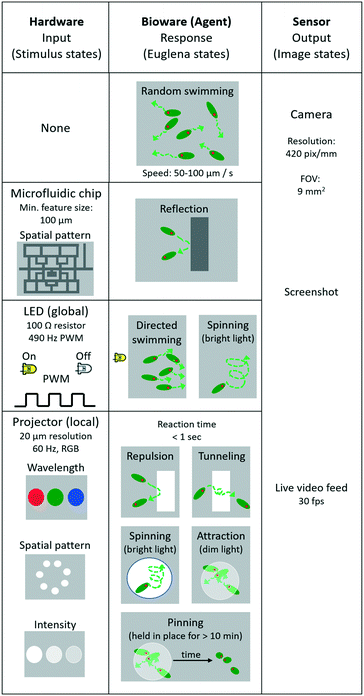
The Euglena stimulus–response is the basis for swarm control, and the direct manipulation of the system actuators (“stimulus space” programming) forms the lowest level of programming abstraction for swarm manipulation, e.g., ‘turn LED on’. In this section, we detail the various Euglena behaviours which emerge from the three stimulus modalities (LEDs, projector, and chip) (Fig. 3). All three stimulus modalities have been demonstrated individually with Euglena before, but they have not yet been combined in one device.31,37,39 Note that Euglena have an inherent degree of variability, which makes complete characterization of all possible Euglena behaviours difficult. Here, we focus on the most robust and consistently observed Euglena responses.No stimulus
When no light stimulus is applied (barring ambient light), the cells engage in persistent random walks with velocities of 50–100 μm s−1 and persistence lengths of 100–500 μm (Fig. 3). Cells weakly influence the trajectories of other cells via hydrodynamic flow; since the chamber height is significantly larger than two cell widths, cell trajectories often cross.Physical barriers
Structured microfluidic chips provide physical barriers for the Euglena (Fig. 3). These structural barriers can be modified through software-actuated pumping (not demonstrated here) or by exchanging the chip altogether, which would also result in the replacement of the entire swarm. Changing chips takes about 5 minutes in this setup.Turn LED on/off
Any of the four side LEDs can be turned on and off simultaneously or separately. This can be done through direct manipulation of the Arduino pins through processing, e.g., Arduino.digitalWrite (ledPin, Arduino.HIGH). Euglena reorient within seconds to swim away from the LED stimulation. The degree to which cells respond depends on light level, i.e., up to a certain point, the higher the light level the higher the degree of Euglena alignment (Fig. 3). At very high intensities, Euglena cells tend to spin in place for a few periods (2–5 seconds) before choosing a direction in which to move. Thus, Euglena trajectories may have sharp rather than gradual changes in direction. Increasing light levels also leads to slight decreases in swim velocity. If an LED is turned off, the Euglena in the chamber will continue to move in the same direction for a short time (<2 seconds) before randomizing their direction.Project image
Projected stimuli may either act as barriers or attractors for Euglena (Fig. 3). This can be done through native Processing commands, e.g., rect(x1, y1, x2, y2). When a pattern is projected at a high intensity of blue light, the cells avoid the high-intensity areas and are repelled locally. Since these barriers do not physically impede movement via steric hindrance, and because Euglena cells move in a pseudo-random fashion, cells often penetrate the barriers slightly, and by chance move into an area of bright projected light. However, after sensing the stimulus, cells will change their directions at random. On occasion, cells will travel even further into the barrier, at which point they will turn more frequently, and eventually leave the barrier on either side. This results in a net avoidance of the projected barrier. Barriers tend to be more effective at high intensities of blue light (see also “Combining stimuli” below).Projecting dim light can form a local attractor. Euglena which swim into an area with dim light will tend to stay within the dimly lit area rather than move onto an unlit area. Again, the projected light does not impede any hydrodynamic flows.
Repeatedly drawing and erasing images (i.e. animation) creates moving barriers and attractors. The slower the animation and the larger the barriers and attractors, the more likely the Euglena will be able to respond to the changes.
When Euglena are held in place for >10 minutes, either by projected barriers or attractors, some of the cells may become immobilized. These cells tend to settle in clusters and are pinned in place, even after the stimulus is removed. This pinning can often be reversed by projecting a bright light at the location of the cluster to which the cells will again exhibit an avoidance response (Fig. 3).
Combining stimulus modalities
The light stimuli and structural modalities (LEDs from the four sides, projector from below, microfluidic mazes) had been used separately in previous setups7,31,37,39 – but not in combination. Within this setup, the Euglena responses to the individual stimuli were found to be equivalent to their responses in previous setups.Our setup combines all three stimulus modalities for the first time. We find that all three stimuli modalities can be used simultaneously, i.e. it is possible to steer Euglena through microfluidic mazes while also using light barriers, which block Euglena movement through certain areas of the chip (Fig. 4, ESI‡ Movie M1). Note that physical barriers are more effective than light barriers, blocking 100% rather than ∼70% of cells. However, they currently cannot be changed through software.
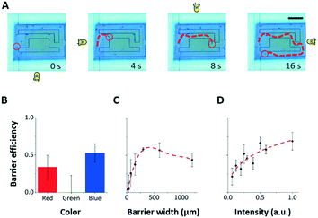 | ||
| Fig. 4 Combining the three stimulus modalities. The three stimulus modalities (LED, projector, microfluidic maze) can be used simultaneously to control Euglena motion. A) The four directional LEDs steer a Euglena cell through a microfluidic maze while projected barriers keep other cells from entering the maze area. Scale bar: 250 μm. See also ESI‡ Movie M1. B–D) The blocking efficiency of a projected barrier is dependent on the wavelength of light, the barrier width, and the barrier intensity. Note that the projector does not project single-wavelength colours. In general, blue barriers work best at the highest intensity with a width of about 300 μm (5–6 cell lengths). Only blue barriers are used to collect data in C) and D). Error bars are 1.0 SEM (N = 4). | ||
To better characterize the projected barrier effectiveness when LED stimuli are also being used, we run a series of experiments in which all of the Euglena cells are driven to the left side before they are driven to the right via the LED stimulus against a projected barrier. The barrier is drawn onto the middle of the screen. After 5 minutes, the number of cells behind the barrier and the number of cells in front of the barrier are counted, and the ratio between the two is called the “blocking efficiency”. The barrier colour, width, and intensity were varied between experiments (Fig. 4B–D). Generally, wide barriers with high intensities of blue light are most effective. Blue barriers are maximally effective at full brightness with a 300 μm width (>5 cell lengths) (Fig. 4). Red light appears also partially effective. This seems contradictory to reports that the Euglena photoreceptor is not sensitive to red light,46,47 but phototaxis in response to red light has been noted by other groups.48,49 Furthermore, the projector used here does not emit single-wavelength colors.
These experiments show that the effects of projected stimuli and LED stimuli can be superimposed. The ability to combine these stimuli modalities creates a significantly larger stimulus–response space for these agents, therefore increasing the expressiveness of the application design space.
Image
The output of the BPU is a sequence of raw images of the FOV (i.e., a live feed of the FOV), capturing the Euglena, chip geometry, and projected images (Fig. 4). This is achieved with the command cam.read(). The LED is sometimes noticeable due to light scattering. These images can be interpreted by a human or processed by higher-level commands downstream.Swarm space programming
Due to the large number of possible stimulus combinations, it is often more straightforward to abstract away from the stimulus space into the higher-level “swarm space”. This is similar to how hierarchies of programming abstractions for conventional computers are used to simplify code and make programming more intuitive. Rather than manipulating the hardware of the BPU, these abstractions describe the desired swarm behaviours (i.e. commanding the living, active matter itself rather than a stimulus), making them generalizable to other systems of swarms. The following are a few examples of swarm space primitives which we defined, essentially capturing the ‘basic spatial arithmetic set.’ Execution times can take minutes to hours depending on the task (Fig. 5, ESI‡ Movie M2).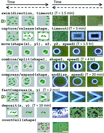 | ||
| Fig. 5 Schematics and microscope images of swarm space primitives which can be executed by Euglena cells within the setup. These commands reflect the desired swarm behaviour rather than the applied stimulus itself. Here the most relevant operations (the ‘basic spatial arithmetic set’) are shown. Time proceeds from left to right, and time required for successful execution (first and last image) is reported. Dashed backwards arrows denote the reversibility of the operation. Scale bars for the microscopy images from top down are: 0.25 mm, 0.5 mm, 1 mm, 0.5 mm, 1 mm, 0.5 mm, 0.1 mm, and 0.5 mm. See also ESI‡ Movie M2. | ||
Swim left/right/up/down
By turning on the right, left, down, or up LEDs, global movement of Euglena toward the left, right, up, or down directions is induced, respectively (Fig. 5), e.g., swim(direction, timeout).Capture/release
Light barriers can be used to isolate subgroups of Euglena from one another (Fig. 5), e.g., capture(shape, timeout).Move
Isolated sets of Euglena can be moved around to specified locations by projecting slowly moving barriers. Captured Euglena respond to the motion of the barriers and adjust their center of mass as the barriers “push” them along (Fig. 5). If the barriers move too quickly (>10 μm s−1), the Euglena cells will not have a chance to rotate and move away from the barrier and thus get left behind, e.g., move(shape(x1, y1), x2, y2, speed).Combine/split
By isolating and moving several subsets of Euglena around at once, groups of Euglena may be combined or split (Fig. 5), e.g., combine(shape1, shape2, speed). It is also possible to separate one group of cells into two or more subgroups by drawing a barrier to separate the subgroups. These subgroups can then be moved independently. Again, the barriers cannot be moved too quickly; to separate a group of Euglena to opposite sides of the FOV may take several hours for maximal Euglena response. These commands are of particular interest for implementing basic swarm logic such as addition, subtraction, and division on the number of Euglena.Compress/expand
By shrinking or expanding barriers, it is also possible to concentrate or dilute the Euglena (Fig. 5), e.g., compress(shape, endsize, speed). Compression by this method takes approximately 5–10 minutes, depending on the size of the initial closed area. Faster compression can be achieved through combining some primitives (see below “Combining commands”).Deposit
Deposition of Euglena can be achieved by holding Euglena cells at high density at a specific location for an extended period of time (>10 minutes) (Fig. 5), e.g., deposit(x, y). This can be done through projected barriers, attractors, or having two or more LEDs on at a time, which forces the Euglena to compress and cluster. When deposited, the Euglena cells will be immobilized onto the chip for multiple minutes. Eventually they will regain motility and swim away. This command illustrates how microswimmers in the future could be utilized to construct more complex and perhaps permanent 3D microstructures.Detect/count cells
Cell detection builds on the setup's imaging ability, which it then uses to detect contours (Fig. 5), e.g., countCell(shape). The contours are stored in memory short-term and compared to the contours generated to allow for near real-time image analysis of velocity and orientation. This is a necessary tool for detecting the system state, and allows for the implementation of commands that require feedback.Combining commands
Some commands may take hours to complete with maximal effectiveness (Fig. 5). Combining primitives can often speed up the process. For example, the command fastCompress combines global directional swimming (i.e. an LED stimulus) against a projected barrier. This compression method is effective within 2 minutes compared to the 10 minutes required for the shrinking barrier alone. This relies on asynchronous execution of commands.System space programming
Higher levels of abstraction include routines, combinations of commands, and conditionals on the Euglena state, which require system monitoring. We call this “system space” programming. Conditionals require the ability to detect the BPU state and act accordingly. Our system enables such detection for feedback, making it more powerful than previous BPUs. This also allows for a greater degree of automation in programming and enables cell interaction with virtual objects and boundaries.31,32 Arbitrarily many system-level commands and programs can be implemented. Here we discuss three examples in detail.Clear screen
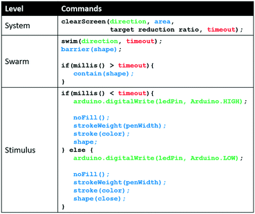
The clearScreen command uses an LED for directional flow of the Euglena and projected barriers which prevents Euglena from entering the area to be cleared (Fig. 6). Euglena detection makes cell counting possible, thus allowing the system to calculate the percentage of cells cleared. After a certain reduction ratio (i.e. percentage of cells on screen compared to the initial count) has been cleared, the cleared area is closed off with another projected barrier to prevent other Euglena cells from entering the region (Fig. 6). A time-out is also set in case the command cannot be executed for any reason (e.g. cells are stuck to the surface, or the population is too dense). A clearScreen command with a target reduction ratio of 10% is typically completed in 2–5 minutes. Table 1 demonstrates the syntax of the clearScreen command as well as the equivalent code in the lower abstraction levels.Clear and collect
The clearCollect command combines the tasks completed by of clearScreen and fastCompress into a single command, i.e., moving the cells out of one area via the LED stimulus and concentrating them in another area via projected light barriers. This command is completed in the typical time it takes to execute the clearScreen command alone (2–5 minutes). This command is one example of a routine made of lower-level commands executed simultaneously, which decreases the time needed to complete an objective. A demonstration of the utility of this command follows in the “Application demonstration” section. Arbitrarily many of these higher-level routines can be created to allow for more efficient programming and command execution. Ultimately, such higher-level commands will emerge as more applications are developed to satisfy their needs.Report system status
The command systemStatus reports the Euglena system state to the user, i.e., using cell detection to determine average cell velocities, cell responsiveness to the LEDs and projected barriers, and cell count. This command can be used in a start-up routine to determine whether the cells are healthy and responsive enough for a particular application. If benchmark conditions are not met (e.g. cell density is too low), the system can take mitigating steps (e.g. flushing in fresh Euglena). If that does not resolve the problem, the application throws an error and fails to start. Start-up routines allow applications, including experimentation, to be more robust. Detection of system status occurs within 30 s. We find that 90% of Euglena cultures pass the system check when initially used, and that the cultures are stable for 1–3 months.Summary of programming levels
We developed three levels of programming abstraction which we now compare side-by-side (Fig. 7): (1) stimulus-level programming, where the hardware (projector, LED, camera) are directly accessed (e.g. ‘turn LED on’); (2) swarm-level programming, which directly considers the resulting Euglena behaviour (e.g. ‘swim right’); and (3) system-level (feedback-based) programming, which includes greater degrees of abstraction and routines (‘clear screen’). One can also consider the structured microfluidic chips as a sort of spatial programming. As it is a hardware modification, the microfluidic maze could be considered zeroth-level programming.Each higher-level of programming requires additional system capabilities. The lowest level (stimulus space programming) can also be thought of as the BPU instruction set, analogous to the machine code or instruction set of a GPU.29 These instructions are carried out independently of whether or not there is a living, responsive biological system, and although the Euglena responses are captured through image acquisition, higher-level image recognition downstream is needed to assess the Euglena behaviour. Second tier swarm commands require responsive cells to be inside the system in order to be executed. For other swarm systems, the stimuli set will vary to achieve these commands.1,18,22,25,35,36 However, the commands themselves are general methods for manipulating matter, and thus are broadly applicable. Finally, system-level commands require the system to be able to monitor its state (i.e. perform image processing) for feedback to occur. For other non-Euglena swarm systems, the commands laid out at this level require the swarm to be able to report its state to a global observer.
Abstracting to higher programming levels allows code to be developed more easily. For example, Table 1 provides a comparison of code for the implementation of the task ‘clear screen’ at each level, illustrating how abstraction can decrease the number of lines of code. Furthermore, we see that the clearScreen can only be fully executed at the highest level because the target reduction ratio requires feedback.
Application demonstration: multi-level game
To evaluate and demonstrate how programmed control over swarm movement could be used in an application, we implemented a simple multi-level puzzle game, ‘Bugs ‘n’ Boxes’ (Fig. 8, ESI‡ Movie M3). The game objective for the player is to add and remove light barriers on the screen in real-time in order to guide a swarm of cells into or away from certain areas. The swarm itself is programmed to swim in various directions either through stimulus space (LED actuation) or swarm space. We describe the programmed game-levels below and highlight the underlying programming aspects.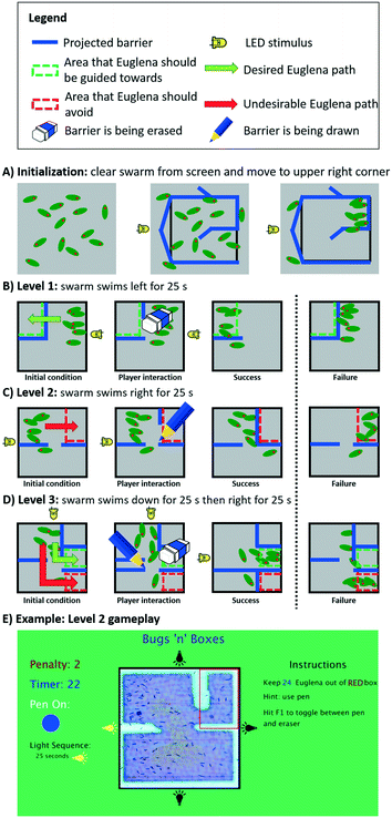 | ||
| Fig. 8 The multi-level proof-of-concept game, Bugs ‘n’ Boxes. This game was created to assess and illustrate the utility of our programming abstractions. A) Before the game starts, the clearCollect command initializes the swarm state by clearing the FOV from cells and simultaneously concentrating them in the upper right corner. B) On the first level, the player must erase a barrier in order to allow Euglena to get to the top left corner. C) On the second level, the player must draw a barrier to prevent Euglena from entering the upper right corner. D) On the third level, the player must both draw and erase barriers to prevent Euglena from entering the bottom right corner, and guide them into the middle right section. E) A screenshot shows the actual game interface of the second level (for scale: Euglena is ∼50 μm long); see also ESI‡ Movie M3 for all levels. | ||
Before the game starts, the clearCollect command is used to move cells into the upper right corner while at the same time clearing the remaining playfield from cells (Fig. 8A). During each individual level, virtual green and/or red boxes are overlaid with the FOV, indicating to the player where the cells should or should not be, respectively, by the end of the time limit. If the player is successful, the game moves on to the next level; otherwise the system resets again to the first level via the clearCollect command.
When the first level starts, Euglena cells are programmed to swim left (via an LED stimulus), while the projector projects a set of light barriers that prevent these cells from entering the green box on the upper left (Fig. 8B). In order for the player to pass this level, the barrier must be erased by the player. When time is up after 25 s, the countCells command is used to determine the number of cells within the green box as well as in the whole FOV for scoring. The number of cells within the green box is compared to total number of cells on the screen, making the game robust against overall variation in Euglena density. The player passes this level if the majority of cells have been guided into the green box.
In the second level, the Euglena are now driven to the right, while the player must prevent them from getting into the upper right corner (indicated by the red box; Fig. 8C). In order to succeed, the player needs to draw a barrier which blocks the cells from entering the red box. Again, after 25 s the cells within this box are counted and compared to the total number of cells on the screen. The player passes this level if the majority of cells remain outside the red box.
The third level combines both approaches, i.e., the player needs to both erase and draw barriers in order to guide the cells into the green box and keep the cells out of the red box. Here, the cells are first programmed to swim down for 25 s, then right for 25 s (Fig. 8D). The player passes this level if more cells end up in the green box than in the red box.
These three levels demonstrate the programming and direction of swarm motion using swarm commands. More complex controls can be achieved using the combination of local and global stimuli.
We implemented this game twice – first using stimulus-level commands with cell counting implemented downstream, and then using a combination of swarm- and system-level commands. There was a 50% reduction in the total lines of code required using the higher-level commands. This demonstrates the utility of having several layers of programming abstractions.
In developing this application, asynchronous commands such as clearCollect naturally arose from the needs of the application (e.g. initialization of the cell position was accelerated by combining two swarm primitives in parallel). This demonstrates how application development motivates the development of new commands and algorithms. We also note that for efficient (i.e. fast) execution of a spatiotemporal program, the state of the system at the end of the execution of one task should be matched to the beginning of the next. In this case, the level layout was always such that after successful completion of one level the cells were already in the correct position for the start of the next level, so further initialization was not required (Fig. 8B–D). In comparison, initialization of cell position in the beginning of the game could take up to a full minute. This application also demonstrates real-time human interaction with the Euglena swarm, making this a flexible platform for experimentation and exploration.
Conclusions
This work has three major contributions: (1) we demonstrated that combining local and global stimuli significantly increases the control over swarms of active particles and the design space for corresponding applications; (2) we developed programming abstractions generalizing from the physical stimuli and biological responses that are specific to our system (i.e., phototactic Euglena stimulated by light), to swarm behaviours that are more widely applicable (i.e., other agents and stimuli); (3) we demonstrated the utility of the device and programming abstractions for swarm manipulations via a multi-level proof-of-concept game.The synergistic integration of global and local stimulus modalities (side LEDs, projector, and microfluidic chip mazes) combinatorically increased the possibilities to manipulate and interact with microscopic swarms compared to previous systems.7,30,31,37–39,50 Having multiple stimulus modalities can also greatly accelerate specific tasks compared to single modality stimulation, e.g. the command fastCompress, which combines the LED stimulus with a projected barrier, is at least an order of magnitude faster than the command compress, which only uses a shrinking projected barrier (Fig. 5). Previously, it had not been established whether it was even possible to combine these two stimulus modalities. For example, the projected barriers might not have been effective against the LED stimulus. This is, to the best of our knowledge, the first time that the global and local light stimuli modalities have been combined successfully in Euglena cells.
The different levels of programming abstractions help developers to conceptualize programs from the point of view of the physical stimulus, the swarm (Euglena) behaviour, or higher-level outcomes, depending on which is more intuitive for the task at hand. This allows for faster application development. We emphasize that the higher-level programming commands are independent of the specific BPU hardware and swarm system: the swarm commands are general in nature, so the presented concepts apply to other swarm systems and stimuli, natural or synthetic. We demonstrated that various tasks could be parallelized to decrease overall execution time, e.g., clearCollect. This, however, is only possible if the commands are spatiotemporally compatible. For example, a global ‘swim left’ command would interfere with a ‘fast compression to the right’ command. This suggests that it might be beneficial to create a task manager which categorizes compatible spatial commands and schedules such commands to be executed asynchronously. We also note that the commands we developed are similar to those used for the control of virtual objects in other contexts. For example, the Script Creation Utility for Maniac Mansion (SCUMM) facilitated the effective design and control of objects in LucasArts adventure games by simple commands (‘walk dr-fred to laboratory-door’),51 similar to commands like move (Fig. 4). A similar Script Creation Utility for swarms could be developed in the future. We expect that these programming languages and command libraries will naturally evolve as more applications are developed.
Directing swarm behaviours within microfluidic chips is necessary to harness active systems for various biomedical, environmental, or synthesis applications.1,15,18,26 Furthermore such systems can be used for STEM education or research at the intersection of computer and life-sciences.52,53 Compared to previous interactive biology setups,30,31,38,39 this system adds a programmable layer to the BPU with feedback controls, easing application development. The game application presented here suggests that this setup could be seen as a biotechnological analogue of the early electronic microcomputer and its programming capabilities.54,55 Its relatively low cost (∼$750), ease of setup and maintenance, many possible applications, and educational potential could initiate its widespread adoption similar to the microcomputer revolution starting in the late 1970s,54 with equivalent technological and educational impact. We expect that further development of both serious and playful applications with such multi-modal setups will increase our knowledge and mastery of swarm behaviours and algorithms.
Acknowledgements
This work was supported by NSF grant #132475. We thank P. Washington, Y. Tiersen and members of the Riedel-Kruse lab.References
- Y. Gao, J. Beerens, A. van Reenen, M. A. Hulsen, A. M. de Jong, M. W. J. Prins and J. M. J. den Toonder, Lab Chip, 2015, 15, 351–360 RSC.
- Z. Gao, H. Li, X. Chen and H. P. Zhang, Lab Chip, 2015, 15, 4555–4562 RSC.
- A. Cavalcanti and R. A. Freitas, IEEE Trans. NanoBiosci., 2005, 4, 133–140 CrossRef PubMed.
- R. A. Freitas, J. Comput. Theor. Nanosci., 2005, 2, 1–25 CAS.
- D. O. Pushkin and J. M. Yeomans, J. Stat. Mech.: Theory Exp., 2014, 2014, P04030 CrossRef.
- D. B. Weibel, P. Garstecki, D. Ryan, W. R. Diluzio, M. Mayer, J. E. Seto and G. M. Whitesides, Proc. Natl. Acad. Sci. U. S. A., 2005, 102, 11963–11967 CrossRef CAS PubMed.
- K. Ozasa, J. Lee, S. Song, M. Hara and M. Maeda, Appl. Soft Comput., 2013, 13, 527–538 CrossRef.
- S. Martel, Biomed. Microdevices, 2012, 14, 1033–1045 CrossRef PubMed.
- K. Ozasa, J. Lee, S. Song, M. Hara and M. Maeda, Lab Chip, 2013, 13, 4033–4039 RSC.
- A. H. C. Ng, M. Dean Chamberlain, H. Situ, V. Lee and A. R. Wheeler, Nat. Commun., 2015, 6, 7513 CrossRef CAS PubMed.
- E. Shoji, H. Nishimori, A. Awazu, S. Izumi and M. Iima, J. Phys. Soc. Jpn., 2014, 83, 043001 CrossRef.
- N. J. Suematsu, A. Awazu, S. Izumi, S. Noda, S. Nakata and H. Nishimori, J. Phys. Soc. Jpn., 2011, 80, 064003 CrossRef.
- G. Katsikis, J. S. Cybulski and M. Prakash, Nat. Phys., 2015, 11, 588–596 CrossRef CAS.
- R. A. Freitas, J. Nanosci. Nanotechnol., 2006, 6, 2769–2775 CrossRef CAS PubMed.
- Y. Hiratsuka, M. Miyata, T. Tada and T. Q. P. Uyeda, Proc. Natl. Acad. Sci. U. S. A., 2006, 103, 13618–13623 CrossRef CAS PubMed.
- Y. Hiratsuka, M. Miyata and T. Q. P. Uyeda, Biochem. Biophys. Res. Commun., 2005, 331, 318–324 CrossRef CAS PubMed.
- V. V. Balzani, A. Credi, F. M. Raymo and J. F. Stoddart, Angew. Chem., Int. Ed., 2000, 39, 3348–3391 CrossRef CAS PubMed.
- R. W. Carlsen and M. Sitti, Small, 2014, 10, 3831–3851 CrossRef CAS PubMed.
- G. Kaloutsakis and G. S. Chirikjian, Robotica, 2011, 29, 137–152 CrossRef.
- J. Werfel, K. Petersen and R. Nagpal, Science, 2014, 343, 754–758 CrossRef CAS PubMed.
- M. Rubenstein, A. Cornejo and R. Nagpal, Science, 2014, 345, 795–799 CrossRef CAS PubMed.
- S. Nain and N. N. Sharma, Front. Life Sci., 2015, 8, 2–17 CrossRef.
- Y. Sumino, K. H. Nagai, Y. Shitaka, D. Tanaka, K. Yoshikawa, H. Chate and K. Oiwa, Nature, 2012, 483, 448–452 CrossRef CAS PubMed.
- L. Liu, E. Tuzel and J. L. Ross, J. Phys.: Condens. Matter, 2011, 23, 374104 CrossRef PubMed.
- M. S. Sakar, E. B. Steager, D. H. Kim, A. A. Julius, M. Kim, V. Kumar and G. J. Pappas, Int. J. Rob. Res., 2011, 30, 647–658 CrossRef.
- R. Di Leonardo, L. Angelani, D. Dell’Arciprete, G. Ruocco, V. Iebba, S. Schippa, M. P. Conte, F. Mecarini, F. De Angelis and E. Di Fabrizio, Proc. Natl. Acad. Sci. U. S. A., 2010, 107, 9541–9545 CrossRef CAS PubMed.
- R. Ni, J. G. Puckett, E. R. Dufresne and N. T. Ouellette, Phys. Rev. Lett., 2015, 115, 8104 CrossRef PubMed.
- I. Navarro and F. Matía, ISRN Robotics, 2013, 10 Search PubMed.
- Z. Hossain, E. W. Bumbacher, A. M. Chung, H. Kim, C. Litton, A. D. Walter, S. N. Pradhan, K. Jona, P. Blikstein and I. H. Riedel-Kruse, Nat. Biotechnol., 2016, 34, 1293–1298 CrossRef CAS PubMed.
- Z. Hossain, X. Jin, E. W. Bumbacher, A. M. Chung, S. Koo, J. D. Shapiro, C. Y. Truong, S. Choi, N. D. Orloff, P. Blikstein and I. H. Riedel-Kruse, in Proceedings of the 33rd Annual ACM Conference on Human Factors in Computing Systems, 2015, pp. 3681–3690 Search PubMed.
- S. A. Lee, E. Bumbacher, A. M. Chung, N. Cira, B. Walker, J. Y. Park, B. Starr, P. Blikstein and I. H. Riedel-Kruse, in Proceedings of the 33rd Annual ACM Conference on Human Factors in Computing Systems, 2015, pp. 2593–2602 Search PubMed.
- L. C. Gerber, H. Kim and I. H. Riedel-Kruse, in Proceedings of the First International Joint Conference of DiGRA and FDG, 2016, 13 Search PubMed.
- H. Kim, L. C. Gerber, D. Chiu, S. A. Lee, N. J. Cira, S. Y. Xia and I. H. Riedel-Kruse, PLoS One, 2016, 11(10), e0162602 Search PubMed.
- P. S. S. Kim, A. Becker, Y. Ou, A. A. Julius and M. J. Kim, Swarm control of cell-based microrobots using a single global magnetic field, 2013 Search PubMed.
- R. W. Carlsen, M. R. Edwards, J. Zhuang, C. Pacoret and M. Sitti, Lab Chip, 2014, 14, 3850–3859 RSC.
- B. Dai, J. Wang, Z. Xiong, X. Zhan, W. Dai, C.-C. Li, S.-P. Feng and J. Tang, Nat. Nanotechnol., 2016, 11, 1087–1092 CAS.
- K. Ozasa, J. Lee, S. Song, M. Hara and M. Maeda, Lab Chip, 2011, 11, 1933–1940 RSC.
- I. H. Riedel-Kruse, A. M. Chung, B. Dura, A. L. Hamilton and B. C. Lee, Lab Chip, 2011, 11, 14–22 RSC.
- N. J. Cira, A. M. Chung, A. K. Denisin, S. Rensi, G. N. Sanchez, S. R. Quake and I. H. Riedel-Kruse, PLoS Biol., 2015, 13, e1002110 Search PubMed.
- B. Diehn, Science, 1973, 181, 1009–1015 CrossRef CAS PubMed.
- N. A. Hill and L. A. Plumpton, J. Theor. Biol., 2000, 203, 357–365 CrossRef CAS PubMed.
- F. Lenci, G. Colombetti and D. P. Hader, Curr. Microbiol., 1983, 9, 285–290 CrossRef CAS.
- D. B. Weibel, W. R. DiLuzio and G. M. Whitesides, Nat. Rev. Microbiol., 2007, 5, 209–218 CrossRef CAS PubMed.
- G. M. Whitesides, E. Ostuni, S. Takayama, X. Y. Jiang and D. E. Ingber, Annu. Rev. Biomed. Eng., 2001, 3, 335–373 CrossRef CAS PubMed.
- C. Reas and B. Fry, AI Soc., 2006, 20, 526–538 CrossRef.
- S. Yoshikawa, T. Suzuki, M. Watanabe and M. Iseki, Photochem. Photobiol. Sci., 2005, 4, 727–731 CAS.
- M. Ntefidou, M. Iseki, M. Watanabe, M. Lebert and D.-P. Häder, Plant Physiol., 2003, 133, 1517–1521 CrossRef CAS PubMed.
- A. Checcucci, G. Colombetti, G. D. Carratore, R. Ferrara and F. Lenci, Photochem. Photobiol., 1974, 19, 223–226 CrossRef CAS.
- A. Checcucci, G. Colombetti, R. Ferrara and F. Lenci, Photochem. Photobiol., 1976, 23, 51–54 CrossRef CAS PubMed.
- S. A. Lee, A. M. Chung, N. Cira and I. H. Riedel-Kruse, in Proceedings of the Ninth International Conference on Tangible, Embedded, and Embodied Interaction, 2015, pp. 273–280 Search PubMed.
- M. L. Black, Games and Culture, 2012, 7, 209–237 CrossRef.
- R. W. Bybee, Science and Children, 2013, 50, 7–14 Search PubMed.
- National Research Council, A Framework for K-12 Science Education: Practices, Crosscutting Concepts, and Core Ideas, The National Academies Press, Washington, DC, 2012 Search PubMed.
- L. Haddon, Science as Culture, 1988, 7–51 CrossRef.
- L. Haddon and D. Skinner, Soc. Sci. Comput. Rev., 1991, 9, 435–449 CrossRef.
Footnotes |
| † An early version of the code is available on GitHub at https://github.com/hirklab/euglena_LOC.git. |
| ‡ Electronic supplementary information (ESI) available. See DOI: 10.1039/c7lc00131b |
| This journal is © The Royal Society of Chemistry 2017 |

