
 Open Access Article
 This Open Access Article is licensed under a
 Creative Commons Attribution 3.0 Unported Licence
Advancements in microfluidics for nanoparticle separation
Thoriq
Salafi
ab,
Kerwin Kwek
Zeming
b and
Yong
Zhang
*ab
aNUS Graduate School for Integrative Sciences and Engineering, Centre for Life Sciences (CeLS), National University of Singapore, 05-01 28 Medical Drive, 117456 Singapore. E-mail: biezy@nus.edu.sg
bDepartment of Biomedical Engineering, National University of Singapore, 9 Engineering Drive 1, Block EA #03-12, 117576 Singapore
First published on 26th October 2016
Abstract
Nanoparticles have been widely implemented for healthcare and nanoscience industrial applications. Thus, efficient and effective nanoparticle separation methods are essential for advancement in these fields. However, current technologies for separation, such as ultracentrifugation, electrophoresis, filtration, chromatography, and selective precipitation, are not continuous and require multiple preparation steps and a minimum sample volume. Microfluidics has offered a relatively simple, low-cost, and continuous particle separation approach, and has been well-established for micron-sized particle sorting. Here, we review the recent advances in nanoparticle separation using microfluidic devices, focusing on its techniques, its advantages over conventional methods, and its potential applications, as well as foreseeable challenges in the separation of synthetic nanoparticles and biological molecules, especially DNA, proteins, viruses, and exosomes.
 Thoriq Salafi | Thoriq Salafi earned his bachelor degree in Biomedical Engineering from the National University of Singapore (NUS). Currently, he is enrolled in a PhD and MBA double degree program at the NUS Graduate School for Integrative Sciences & Engineering (NGS) and NUS Business School. His current research focuses on microfluidic sorting and bioelectronics for medical diagnostics and commercialization. |
 Kerwin Kwek Zeming | Kerwin Kwek Zeming is a Postdoc Research Fellow at the Department of Biomedical Engineering, National University of Singapore (NUS). His PhD thesis investigates novel pillar shapes in deterministic lateral displacement microfluidic devices for the separation of key bio-particles, such as red blood cells and bacteria. His research interests include advances in nano/microfluidics for the detection of biological particles. |
 Yong Zhang | Yong Zhang is a Professor and Deputy Head of Research at the Department of Biomedical Engineering, National University of Singapore (NUS), and a senior member of NUS NanoCore Research Institute and NUS Graduate School for Integrative Sciences and Engineering (NGS). His current research interests include nanobiophotonics, nanomedicine, biomedical microdevices, and tissue engineering. |
Introduction
Nanoparticles have been widely employed for industrial applications spanning from photovoltaics,1 supercapacitors,2 cosmetics,3 food,4 and drug delivery,5 to medical diagnostics6 and therapy.7 The sorting and separation of nanoparticles from heterogeneously sized mixtures are essential as nanoparticle synthesis procedures often result in a polydispersed size, and the physical and chemical properties of these nanoparticles depend on their size.8,9 More importantly, high-performance nanoparticle sorting methods to filter nanoparticles from household and industrial waste are critical, as exposure to these nanoparticles introduces new hazards to health and the environment.10,11 Improvement in nanoparticle separation methods is also important for the development of medical diagnostic tools, as biomolecules are often used as disease biomarkers, and the detection of viral particles is of great interest for viral diagnostics.12,13 Moreover, recent research on nanometer-sized extracellular vesicles, such as exosomes, draws great interest for medical diagnostics and therapeutics.14 The purification and separation of these extracellular vesicles from other molecules present in a sample are one of the challenges to be overcome before further diagnostic steps can be performed.15 There are several conventional techniques that have been commonly applied to perform these functions, including ultracentrifugation, electrophoresis, chromatography, filtration, size-selective precipitation, and solvent addition.9,16 These techniques are proven to have high separation efficiency and reproducibility. However, they still have significant limitations, including the need for a minimum sample volume, multi-step preparation, and performance in batch mode. Additionally, each individual separation technique requires specific optimization for the separation of various nanoparticles, depending on sample properties, such as purity, density, solubility, hydrophobicity, solution conductivity, and particle isoelectric charge. As a result, the development of tools capable of addressing these drawbacks is needed to obtain more robust, versatile, and high-performance nanoparticle separation.Recently, continuous particle separations with microfluidic technologies have been widely implemented due to their low cost, low sample volume, and minimal sample handling with precise control. Various microfluidic techniques have been explored extensively to separate micro-sized particles, such as blood cells,17 spores,18 parasites,19 circulating tumor cells,20 and bacteria.21 Several review papers have also discussed microfluidics for microparticle and cell separation.22–25 To separate submicron particles, nanofluidics has emerged as a suitable technique for separation. However, fabrication of nanofluidic devices increases complexity and requires expensive equipment.26 Meanwhile, the advancement of microfluidics research has extended the separation resolution to reach the nano-regime, so as to perform nanoparticle purification and DNA isolation with superior efficiency compared to conventional nanoparticle separation methods. However, microfluidic techniques for nanoparticle separation have not been explored extensively, despite gaining momentum in recent years. This review gives an overview of traditional techniques to separate nanoparticles and explains the current development of nanoparticle separation methods using microfluidics, their advantages, applications, and foreseeable challenges for the separation of nanoparticles and biological molecules.
Conventional techniques for nanoparticle separation
Nanoparticle separation techniques have been employed for industrial and research applications for a long time, and several gold-standard techniques have been widely implemented for synthetic nanoparticle and biomolecule separation. These conventional nanoparticle separation techniques can be classified into three main categories: separation using an external field, sieving, and colloidal stability.External field
Nanoparticles have intrinsic properties, such as size, density, magnetic properties, electric properties, and aggregation tendency. These properties could be used to fractionate nanoparticles using external fields, such as centrifugal force or an electric field. These two external forces have been commonly applied for nanoparticle sorting, namely, ultracentrifugation and gel electrophoresis. Ultracentrifugation is the most common technique for separating and purifying nanoparticles. This technique relies on the particle deposition through centrifugal force arising from the rotation of the ultracentrifuge. Ultracentrifugation is able to separate nanoparticles by size and shape, and the resolution can be improved with an additional gradient agent. Sun et al. demonstrated the separation of FeCo@C and gold nanocrystals by varying the density gradient and ultracentrifugation duration. Sharma et al. were able to separate gold nanoparticles and nanorods based on their shape, as there is a distinction between the hydrodynamic behavior of rods and spherical particles under centrifugation.27,28 Although this technique is simple, the resolution is limited and requires a density gradient to achieve better separation at the nanoscale. Furthermore, sample loss during purification is inevitable, and exposing the particles to a large gravity force, which can be up to 16![[thin space (1/6-em)]](https://www.rsc.org/images/entities/char_2009.gif) 000g, increases the tendency for the particles to aggregate.29 Furthermore, the requirement for specialized equipment for ultracentrifugation makes this technique relatively expensive to apply for nanoparticle separation. Besides ultracentrifugation, gel electrophoresis is also extensively employed for DNA and nanoparticle separation, with high resolution, depending on the gel pore size. Gel electrophoresis separates samples based on their size/charge ratio when the particles are suspended in an electric field. Liu et al. demonstrated separation based on the size and shape of silver nanorods and nanoparticles with capillary electrophoresis.30 Gel electrophoresis has also been shown to separate various metal nanoparticles by size, shape, and charge with high resolution.31,32 Although it is a gold standard for protein and DNA separation, this technique is batch-limited and requires multiple steps to operate, takes a long time for sample separation, and is cumbersome for sample retrieval.33
000g, increases the tendency for the particles to aggregate.29 Furthermore, the requirement for specialized equipment for ultracentrifugation makes this technique relatively expensive to apply for nanoparticle separation. Besides ultracentrifugation, gel electrophoresis is also extensively employed for DNA and nanoparticle separation, with high resolution, depending on the gel pore size. Gel electrophoresis separates samples based on their size/charge ratio when the particles are suspended in an electric field. Liu et al. demonstrated separation based on the size and shape of silver nanorods and nanoparticles with capillary electrophoresis.30 Gel electrophoresis has also been shown to separate various metal nanoparticles by size, shape, and charge with high resolution.31,32 Although it is a gold standard for protein and DNA separation, this technique is batch-limited and requires multiple steps to operate, takes a long time for sample separation, and is cumbersome for sample retrieval.33
Sieving
In addition to external fields, physical holes or barriers, such as membranes or columns to filter particles based on their properties, are often used for nanoparticle separation. The commonly used sieving techniques to separate nanoparticles are chromatography and nanofiltration. In chromatography, samples are separated in a mobile phase through a stationary phase, and the rate of separation depends on the partitioning speed of the particle through the stationary phase. There are several types of chromatography for nanoparticle separation, such as size-exclusion, affinity, ion-exchange, and high-performance liquid chromatography.34 This technique has high separation efficiency, but requires a long time, multiple preparation steps, and specialized beads, antibody and buffers for separations. Wei et al. applied size-exclusion chromatography with 100 nm pore polymer-based columns to separate gold nanoparticles with a size range of 5.3 to 38.3 nm.35 Another sieving technique that relies on a membrane is nanofiltration. This is a simple process for particle separation, which allows particles smaller than certain cut-off sizes to pass through the filter. Different membrane materials have been implemented for nanosized filtration. Benfer et al. implemented a filtration technique with a ceramic membrane for nanoparticle separation.36 A supramolecular membrane has been demonstrated to separate nanoparticles in the sub 5 nm size range, which has the capability to be recycled many times.37 The filtration technique is fast, requires a small volume of solvent, and can be scaled to large sample separation for industrial application. However, the membranes are prone to clogging, subsequently inducing particle aggregation, which could decrease the throughput of separation. It also requires many steps to separate samples with multiple particle sizes.Colloidal stability
Another bulk separation method for nanoparticle fractionation is to alter the nanoparticle stability and dispersibility based on size or aggregation tendencies with size-selective precipitation (SSP) or solvent addition. Size-selective precipitation relies on aggregation of nanoparticles caused by the addition of unique solvents tailored to nanoparticle surface chemistry, reactivity, or stability. Most of the nanoparticles are surface-modified to improve stability and dispersion in the solution, commonly by charge or steric hindrance. This stability can be disrupted by introducing non-miscible solvents that result in aggregation. Once the aggregation of the nanoparticle is achieved, centrifugation is performed to isolate the non-aggregated nanoparticles left in the supernatant. Rapid salt-based size precipitation has been applied to separate larger nanocrystals from smaller ones by merely adjusting the concentration of the salt in the sample, without requiring traditional heating or condensation of the mixed solutions.38 In solvent addition, the dispersibility of nanoparticles is manipulated by adding two solvent systems, a highly miscible solvent and a poorly miscible solvent, which induce aggregation and precipitation of the well-dispersed nanoparticles in a solution. Saunders et al. tuned the solubility and dispersibility of nanoparticles through carbon dioxide gas-expanded liquids with non-polar aliphatic ligand hydrocarbons, such as hexane, to aggregate and precipitate gold and silver nanoparticles.39 In another study, Duggan and Roberts utilized a DMSO solvent system to alter the dispersibility of gold nanoparticles.40Nanoparticle separation in microfluidics
Advantages of microfluidics for nanoparticle separation
Conventional techniques to separate nanoparticles have several limitations that reduce the overall performance of the separation. The traditional ways of nanoparticle sorting, such as chromatography and electrophoresis, require hours of time and a large volume of sample for separation. Some methods, such as selective precipitation and ultracentrifugation, have inevitable sample loss during the separation process, while several sieving sorting techniques, such as SSP, chromatography, and nanofiltration, induce sample aggregation. Microfluidics offers miniaturization of conventional techniques, which reduces the minimum sample volume, as well as introducing improvements in the duration and resolution of separation. Microfluidics provides continuous separation for multiple sample sizes and allows for minimum aggregation and sample loss during the separation process. Microfluidics also offers superiority beyond the separation process, as it is able to give real-time control, such as size control, by modulating the experimental parameters, such as the buffer solution and the external field. Furthermore, microfluidics also provides a low-cost solution for nanoparticle and biomolecule separation, which could be easily integrated with other techniques, such as mixing, counting, detection and analysis. On the other hand, nanofluidics has been an emerging area for nanoparticle study, including nanoparticle separation with very high separation efficiency and resolution; however, fabrication of nanofluidic devices is more expensive and complex, as it needs smaller and more precise fabrication to produce submicron-sized channels. Furthermore, nanofluidics for nanoparticle separation holds challenges associated with a very small throughput, such as in nano-DLD with a gap size of 25 nm, which has a flow rate of 0.1–0.2 nL min−1, as compared to ∼1 μL min−1 in microfluidics.41 Therefore, microfluidics holds the upper hand for nanoparticle separation compared to both conventional techniques and nanofluidics.Nano-regime separation in microfluidics
Microfluidics for microparticle separation has been well-established and widely applied, mainly for cell separation. There is an increasing trend to push the boundaries of microfluidic separation towards nano-regime separation. However, several microfluidic separation techniques that have been successfully employed for microparticle separation are facing difficulties with implementation for nanoparticle separation. The commonly known parameters that influence the breakdown of separation in the nano-regime are size, diffusion, conformational structure, surface forces, pH, and buffers. To sort particles, additional forces need to act on the particle to displace it away from its initial position. For sorting forces, such as dielectrophoresis, acoustophoresis, and inertial microfluidics, the effect of size reduction toward the nano-regime exponentially reduces the sorting forces acting on a particle, as the magnitude of the force acting on the particle is largely dependent on size.42–44 This can be solved by increasing the magnitude and frequency of acoustophoresis and dielectrophoresis to cater for nanoparticle separation.45,46 The details of the effect of this smaller radius on separation are discussed in the following section for each microfluidic technique. In addition, a smaller size would result in faster Brownian motion of the nanoparticle, which could impede its separation in certain microfluidic techniques.47 This is especially so when the effect of Brownian motion is more prominent as compared to sorting forces, which results in poor separation resolution. This can be tackled by increasing the primary sorting force or using different approaches to decrease the time-dependent diffusive effects, such as reducing the transit time of the particles within the device. There is a large branch of microfluidics that utilizes the microstructural fabrication of channels, pores, pillar obstacles, and filtration membranes to selectively separate particles by size with sieving or laminar flow-based methods.48–50 The need to fabricate and characterize these structures at the nanoscale for nanoparticle separation may require specialized and expensive methods, such as e-beam lithography, nanoimprint lithography, or the use of controlled material deposition and growth in pores.49 Furthermore, unlike microparticles, such as cells, that mostly have relatively round and uniform shapes, nano-biomolecules, such as DNA, RNA, and protein, have unique shapes, structures, topology, and conformations, which increase the difficulties in the sorting process. On top of these challenges, the reduction in size for nanoparticles introduces significant properties and influences that are generally negligible in microparticle separation. Nanoparticles have higher surface to volume ratios, which results in higher surface energy, and hence they become more prone to aggregation as compared to microparticles.51 This leads to the importance of microfluidic surface treatments, as well as the choice of buffer solutions, to prevent nanoparticle aggregation during separation. Moreover, due to its small size, the electric double layer length of a nanoparticle may be comparable to its size. For example, in deionized water, the Debye length of the nanoparticle is 311 nm, which might be much larger than the size of proteins, DNA, and RNA.52 This infers that nanoparticle surface interaction forces, which comprise electrostatics,53 hydrophobic,54,55 and Van der Waals forces, need to be carefully balanced and understood. As these effects become more prominent, the separation behavior of nanoparticles depends largely on the properties of the surrounding environment, such as materials, solvent, pH, and temperature.56 These nano-regime properties can be used either to achieve nanoparticle separation or degrade the separation. For instance, separation resolution in most microfluidic techniques can be disrupted by diffusion, while for other techniques, diffusion can be employed as the driving force for nanoparticle separation.57 Furthermore, the new separation technique of electrostatic sieving can be employed for nanoparticle separation in microfluidics due to the large influence of surface interaction forces on nano-regime microfluidics.53Microfluidic techniques for nanoparticle separation
Microfluidics is able to separate nanoparticles continuously with relatively simple preparation steps compared to traditional methods. These particle-sorting techniques can be classified into active and passive separation.22 The active technique requires an external field to drive the separation; on the other hand, the passive technique only relies on the inherent properties of microfluidics, such as hydrodynamics, channel geometry, and additionally surface forces for nanoparticle separation. Table 1 below summarizes recent studies on nanoparticle separation using microfluidic techniques.| Techniques | Mechanism | Separation marker | Nanoparticles separated | Efficiency | Throughput | Advantages | Drawbacks | Ref. |
|---|---|---|---|---|---|---|---|---|
| Field flow fractionation | Asymmetrical flow FFF | Size | 5–250 nm | 87–88% | 400–1100 μL min−1 | Very high throughput with high separation efficiency | Requires specific sample, solvent or membrane | 63 and 64 |
| Centrifugal | Centrifugal force | Size, density | 50 nm, 100 nm, and 200 nm | — | 500 μm s−1 (∼7.5 μL min−1) | High throughput, does not require density gradient and dilution | Needs centrifugation equipment, not continuous separation | 75 |
| Optical | Optical force | Size, refractive index, polarizability | 70 nm, 500 nm, and 1 μm | — | 100 μm s−1 (∼0.375 μL min−1) | High separation efficiency | Heating and photo damage to particles, low throughput | 80 |
| Affinity capture | Surface interaction | Antigenic site, hydrophobicity, charge | 100 nm | — | 10 μL min−1 | High capture efficiency and purity | Expensive antibody, multiple preparation steps | 107 |
| Electrophoresis | Uniform electric field | Size, charge | <50 nm | 97% | 0.4 μL min−1 | Very high separation efficiency and resolution | Flow rates change with chemistry (buffer types, wall effects) | 116 and 161 |
| Dielectrophoresis | Non-uniform electric field | Polarizability and size | 30 nm, 60 nm | 85–100% | 10 μm s−1 (∼0.009 μL min−1) | High throughput and separation efficiency | Requires high voltage, depends on medium conductivity, very low throughput | 124 |
| Magnetophoresis | Magnetic field | Size, magnetic properties | 5 nm, 7 nm and 200 nm | 90% | 300 μL min−1 | Very high throughput, requires relatively low cost | Requires long time for magnetic bead antibody labelling | 85 and 88 |
| Acoustophoresis | Ultrasonic sound wave | Size, density, compressibility | <200 nm | >90% | 1.5–2.8 mm s−1 (0.43–0.81 μL min−1) | High separation efficiency, controlled cut off separation | Complex fabrication, limited device material to transmit acoustic power efficiently | 45 |
| Ion concentration polarization | Electric field | Size, electrophoretic mobility | 500 nm, 100 nm | — | 0.5 μL min−1 | Requires low voltage, does not require internal electrode | Low resolution on small size particles and low throughput | 137 |
| Electrohydrodynamic vortices | Travelling waves, ohmic heating | Size, charge | 200 nm | ∼100% | 0.033 μL min−1 | High separation efficiency | Complex fabrication of microelectrode, low throughput | 140 |
| Deterministic lateral displacement | Laminar flow stream | Size, deformability and shape | 190 nm, 2 μm and 600 nm | ∼100% (20 nm resolution) | 400 μm s−1 (∼0.01 μL min−1) | Controllable cut off size and simple and efficient technique with very high separation efficiency | Very low throughput, requires precise fabrication, pillar clogging issue | 152 and 156 |
| Hydrodynamic filtration | Hydrodynamic sieving | Size | 100 nm and 1 μm | — | 1 μL min−1 | Simple technique, high separation efficiency, medium throughput | Prone to membrane clogging | 48 |
| Spiral microfluidics | Dean vortices | Size, shape | 590 nm,1.9 μm and 7.32 μm | 95% | 10 μL min−1 | Very high separation efficiency, throughput, and simple technique | Prone to particle–particle interaction and diffusion disruption | 162 |
| Straight inertial microfluidics | Shear and wall lift | Size, shape | 590 nm, 780 nm, and 1.9 μm | — | — | Very high throughput, separation efficiency, and simple technique | Prone to particle–particle interaction and diffusion disruption | 144 |
| Electrostatic sieving | Electric double layer force | Size, charge | 19 nm and 39 nm, 50 nm | 97% | 0.6 μL min−1 | Very high separation efficiency and controllable cut-off size with buffer | Only able to separate nanoparticles in low ionic conditions, low throughput | 53 and 163 |
| Bacteria chemotaxis | Chemotaxis diffusion and bacterial motility | Selective adhesion on bacteria | 320 nm and 390 nm | 81% | 2.4 × 10⁵ particles per min (∼0.013 μL min−1) | Simple and low cost technique | Requires antibody conjugation for selective adhesion to bacteria, very low throughput and relatively medium separation efficiency | 164 |
Active separation
Integration of microfluidics with external fields gives superiority to the separation as it can sort, deflect, or trap the particles based on their intrinsic properties to overcome Brownian motion. Several active separation techniques that have been implemented for nanoparticle separation include field flow fractionation, centrifugal microfluidics, optical techniques, magnetophoresis, acoustophoresis, electrophoresis, dielectrophoresis, ion concentration polarization, and electrohydrodynamic vortices.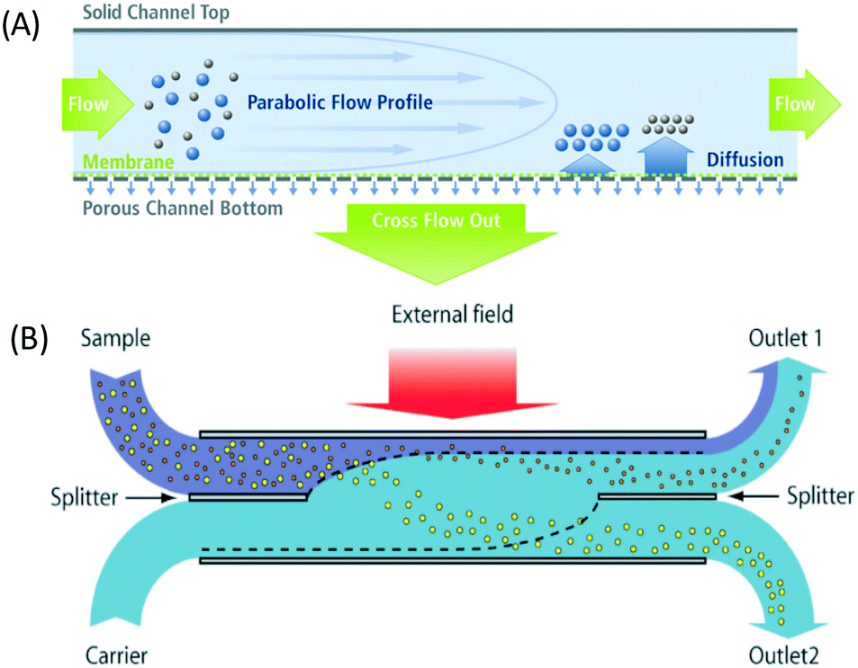 | ||
| Fig. 1 The field flow fractionation principle combines the parabolic profile, an external field, and diffusion to separate nanoparticles. (A) Asymmetrical flow FFF has a porous semipermeable membrane at the bottom of the channels. Reproduced from ref. 70 (B) Continuous separation using SPLITT, which is a modified FFF achieved by adding a splitter on both inlet and outlet channels. This allows fractionation of particles to different outlet locations based on particle size. Reproduced from ref. 25 with permission from The Royal Society of Chemistry. | ||

The downstream velocity (v) depends on the hydrodynamic resistance of the channel (Rtot), the input and output channel distances, and the area of the channel (A)

Using this method, nanoparticles with sizes of 50 nm, 100 nm, and 200 nm can be separated by a microfluidic flow under a centrifugal force field without applying a density gradient, as the larger or denser particles are deflected towards the outer wall, while the smaller or less dense particles stay near the inner wall, as shown in Fig. 2.75 Another centrifugal microfluidic technique designed by Kwon et al. was able to separate nanoparticles based on the difference in the velocity and duration of centrifugation between 300 nm and 700 nm particles using 2 × 2 inlets and outlets.74,76 However, the requirement of for centrifugation equipment makes centrifugal microfluidics relatively expensive to apply for nanoparticle separation and it cannot perform continuous separation like other microfluidic techniques.
 | ||
| Fig. 2 Density-free centrifugal microfluidic design shows multi-sized nanoparticles at the inlet channel and separation of the particles by the centrifugal force to different collector bins based on size and density. The smaller or less dense particles are less affected by the centrifugal force and stay at the inner wall of the channel, while larger or denser particles are displaced to the outer wall of the channel. Reprinted with permission from ref. 75 Copyright 2014 American Chemical Society. | ||

where c is the speed of light, m is the ratio between the refractive index of the particle and the medium, and r is the vector of position. As can be inferred from these equations, nanosized particles have very small scattering forces, as these are related to the power of six of the radius, which means that larger particles can be influenced by both Stokes drag and optical force, while smaller particles are only affected by hydrodynamic forces. Yang et al. reported that a combination of hydrodynamic focusing and subsequently optical force treatment could separate a 70 nm particle from 500 nm and 1 μm particles, as illustrated in Fig. 3.80 They used a single-mode optical fiber with a numerical aperture of 0.12 perpendicular to the hydrodynamic flow direction. This can be achieved as the optical gradient force is strong on particles with a mid-size of 500 nm, and propels the particles to travel to the light source, while particles larger than that (1 μm) are more influenced by the radiation force that forces the particles to move further away from the fiber source. Near the wall, the wall lift force equilibrates the particle position and causes it to move in a straight line after separation. In another study by Shi et al., the separation of 200 nm from 500 nm particles with an interference pattern from double-axicon optofluidics was demonstrated.81 Separation with an optical force results in high separation efficiency and throughput, although the usage of an optical force, such as optical tweezers, could induce heating or photodamage in the sample.82

 | ||
| Fig. 3 Focused polydispersed particles from a center flow are fractionated in the microchannel by the optical force perpendicular to the flow. The largest particles (1 μm, orange) are more influenced by the optical scattering force that pushes them away from the fiber source. Particles larger than 200 nm (green) are predominantly influenced by the optical gradient force that manipulates their trajectories towards the optical fiber source, while the smallest particles (50 nm, blue) are unaffected by the optical forces and continue to follow the streamline. | ||
Magnetophoresis
Magnetophoresis utilizes the magnetic susceptibility properties of both particles and fluid for separation. There are two types of magnetophoresis microfluidics based on the source of the magnetic field, one with embedded electromagnetic strips that need to be integrated during fabrication, and another that simply uses an external magnet to actuate magnetic particles. The particle movement under a magnetic field can be classified into positive and negative magnetophoresis. In positive magnetophoresis, particles move towards the higher magnetic field, while in negative magnetophoresis, particles travel away from the magnetic source due to the mismatch between the magnetic susceptibility of the particle and fluids.83The force on a particle in a magnetic field depends on the difference in the magnetic susceptibility of the particle and the fluid (Δχ = χp − χf), the magnetic flux density (B), and its gradient (∇B), which is expressed as,83,84

 | ||
| Fig. 4 Superparamagnetic magnetite nanocrystal clusters (SMNC) selectively attach to the hemoglobin, and the conjugated hemoglobin particles are separated from the mixture of unbound bovine serum albumin when the magnetic field is introduced to the channels. Reproduced from ref. 88 with permission from SpringerLink. | ||
where the acoustic pressure can be determined by p = (PZ/A)0.5, in which Z is the acoustic impedance, A is the area of the IDT, and P is the power of the input. The ϕ is the acoustic contrast factor, which determines the direction of the particle movement. This factor is expressed as42


Particles with a positive ϕ move towards the node, while particles with a negative ϕ value travel towards the antinode. Using this principle, Collins et al. separated nanoparticles with sizes of 500 nm and 300 nm using virtual deterministic lateral displacement by SSAW with high efficiency and throughput.101 Lee et al. reported the separation of 190 nm and 1 μm particles using a standing surface acoustic force with a cut-off particle size separation determined in situ by modulating acoustic power and flow speed.45 Destgeer et al. demonstrated TSAW with a frequency of 200 MHz to separate 710 nm from 3 μm particles.99 While SSAW has a trade-off between particle displacement and the width of the sorting region, TSAW requires a higher strength of acoustic waves and frequency than SSAW to see the effect of separation due to the exponential decrease in acoustic strength.102 Acoustic separation has high versatility, quick actuation, and is contact-free, biocompatible and has a high separation efficiency; however, application of a high acoustic frequency leads to a high acoustic streaming velocity that can cause the disruption of laminar fluid flow and hence separation in microfluidics.103
Affinity-based sorting
Affinity separation has been widely employed to separate particles based on their affinity to specific surfaces, materials, and binding targets, which enables separation of bound particles from unbound ones. This technique can be independently implemented to separate nanoparticles by nanoparticle immobilization or can be integrated with other techniques, such as bead-based separation, using active separation methods like magnetophoresis. Conventionally, nanoparticles can be sorted with affinity chromatography by selectively binding a target that has an affinity to the stationary phase, such as the separation of nanoparticles produced from a molecularly imprinted polymer.104 In microfluidics, this technique is most commonly used to separate biomolecules, such as proteins and exosomes. As biomolecules harbour unique sites for binding to specific antibodies, this can be utilized for their purification from a mixture of molecules. An example here is the purification of exosomes from a biological sample using the CD63 target in ExoChip microfluidics by way of the immunocapture method.105 In addition to antibody-based binding, aptamers were also recently developed for selective purification of small molecules, peptides, and viruses. For instance, microfluidics with aptamer-conjugated beads has been used to purify adenosine monophosphate from a mixture of molecules.106 In addition to specific binding, another type of affinity-based sorting uses non-specific surface adsorption, such as hydrophobic and electrostatic interactions, to capture nanoparticles or biomolecules. A hydrophobic immobilization technique has been demonstrated using a pH-responsive coating of p(NIPAAm-co-pAA) on nanoparticles. This coating induces hydrophobic attachment of the nanoparticles onto the channel surface at low pH.107 Although non-specific surface adsorption is less specific and weaker than antibody or aptamer binding, specific affinity binding is often expensive as it requires a monoclonal antibody for target capture.108| FEP = 6πζpεfaE |
| FDEP = −2πεfa3Re(fCM)E·∇E |
in which

 is the complex permittivity of the particle and
  is the complex permittivity of the fluid, which can be derived from the permittivity value, the conductivity (σ) and the angular frequency (ω) of the electric field
This Re(fCM) value determines whether the particles undergo positive or negative DEP, with a positive Re(fCM) inferring positive DEP and vice versa.44 Both positive and negative DEP has been widely used for separation of nanoparticles and biomolecules.123 Computational fluid dynamic simulation has demonstrated the possibility of continuous separation of 30 nm from 60 nm gold nanoparticles using dielectrophoresis.124Fig. 5 depicts the nanoparticle separation design using insulator dielectrophoresis. This nanoparticle separation is performed by applying streaming DEP with a low electric field to concentrate the nanoparticles in a highly parallel channel and subsequently trap the particles with a higher electric field at a later stage of the low-branching microfluidic channel.125 In addition to the branched channel, insulator DEP has been studied to separate nanoparticles with insulating pillars in a microfluidic channel that induces a non-uniform electric field across the pillar gaps to concentrate nanoparticles.126 Another DEP design to separate nanoparticles is an asymmetric S-shaped ridge, which is able to amplify the electric field by up to 9 times the bulk field. This design, which is reported by Viefhues et al., is able to separate 20 nm and 100 nm nanoparticles.127 As the DEP separation technique is based on the intrinsic properties of the particles, it does not need an immunochemical labeling process. However, dielectrophoretic particle sorting has a low throughput and is highly dependent on a medium conductivity, which makes it difficult to separate nanoparticles with specific solvent molecules.128,129 In addition, the voltage requirement is very high, mostly several hundred volts to kilovolts, which leads to the formation of electrothermal flow and joule heating, which can interfere with the separation process.130 This technique is also challenging as there are various parameters to be optimized for controlled nanoparticle separation, including electric field strength, buffer solutions, surface properties, and geometrical design.
 | ||
| Fig. 5 Designs of DEP for nanoparticle separation. (A) Insulating-pillar DEP and (B) insulating trees for nanoparticle separation. Reproduced from ref. 131 From SpringerOpen (C) DEP nanoparticle separation using ridge structure. Reproduced from ref. 127 with permission from The Royal Society of Chemistry, and (D) sawtooth structures. Reproduced from ref. 46 with permission from The Royal Society of Chemistry | ||
 | ||
| Fig. 6 Nanoparticle separation using ion concentration polarization with a Nafion nanojunction, which generates a repulsion distance, depending on the electric field strength in the ion-depletion region. A low electric field produces a small repulsion distance, while a high electric field traps the nanoparticles in the ion depletion region. Reproduced from ref. 137 with permission from Nature Publishing Group. | ||
 | ||
| Fig. 7 Nanoparticle trap using electrohydrodynamic vortices formed in a high-frequency electric field generated with parallel microelectrode strips on the channel. The electric field produces travelling waves and ohmic heating, which generates hydrodynamic vortices. Near the microelectrode, the DEP force pushes the particles upward, which supports the particle trapping. | ||
Passive separation
Although active techniques have a high separation performance, they are still limited by the need for integration with other equipment to provide an external field, or specific substances, such as antibodies. On the other hand, passive techniques use label-free methods to separate nanoparticles and do not require any external field as the driving force for separation. Instead, hydrodynamic and surface forces are the primary separation mechanism. Six types of passive techniques that have been reported to sort nanoparticles are inertial, spiral, deterministic lateral displacement, hydrodynamic filtration, electrostatic sieving, and bacterial chemotaxis.in which v is the fluid velocity, ρ is the particle density, Dh is the hydraulic diameter, and d is the particle diameter. From this formula, it can be inferred that the smaller the diameter, the greater the reduction in the inertial lift force. For straight microchannels, the particle velocity focused at the lift equilibrium position can be determined by the particle Reynold number (Rep), which depends on the Reynold number (Re), and the square of the particle diameter and the channel ratio


Different shapes of channel, including circle, square, rectangle, and trapezium have been reported for inertial separation. However, only a high-aspect rectangular channel developed by Bhagat et al. has been reported to be able to separate nanoparticles of sizes 590 nm and 780 nm.144 There is a limit to the minimum nanoparticle size to be separated if only the lift force based on the channel geometry is used. However, by using a viscoelastic fluid medium to generate a medium elastic force, in addition to the wall inertial lift force, nanoparticle separation of sizes 500 nm and 200 nm can be achieved.145
 | ||
| Fig. 8 Inertial force equilibration (A) circular and square channels show uniform particle position near all the side walls, while the rectangular channel inertial force results in a unique particle position only on the left and right side of the walls, which allows it to separate nanoparticles in the branched channel. Reproduced from ref. 144 with permission from SpringerLink (B) Spiral microfluidics separates particles by a combination of the lift force (FL) and the Dean force (FD). Larger particles tend to move towards the inner wall, while smaller particles disperse over the channel, as they are influenced more by Dean vortices. Reproduced from ref. 146 with permission from The Royal Society of Chemistry. (C) Inertial microfluidics with viscoelastic fluids concentrates DNA and nanoparticles to the center of the channel through a medium elastic force, in addition to the wall lift force. Reproduced from ref. 145 with permission from The Royal Society of Chemistry. | ||
Another inertial microfluidic geometry that has been used to separate nanoparticles is spiral channel. This spiral geometry induces centrifugal forces on the particles, causing them to travel outwards. On top of that, in a curved channel with a relatively high Reynold number, a secondary flow is present in the form of two symmetrical vortices that can spread small particles on the channel without affecting larger particles positioned near the outer wall. This force is termed Dean vortices and can be expressed by a Dean number (De),25

| De = 1.8 × 10⁻⁴ × De1.63 |
Five-loop spiral microfluidic channels based on these principles were implemented by Bhagat et al., who demonstrated the sorting of 590 nm from 1.9 μm and 7.32 μm fluorescence-labeled polystyrene beads with a throughput of 10 μL min−1.147 The inertial microfluidic technique is simple because it only relies on the force from both the fluid and the wall, while also generating a high throughput. However, particle–particle interactions can act as an internal force in disrupting the equilibrium between the fluid and wall lift force, which may lead to a reduction in separation efficiency.22
| Dc = 1.4Gε0.48 |
Based on this Dc formula, a device with a small gap or row shift fraction is required to separate nanosized particles. However, a small gap size leads to high channel resistance and difficulty in fabrication, while a low row shift fraction design needs a longer region for separation, which increases the diffusion length. Alternatively, the use of different pillar shapes, such as triangle,154 I-shaped,151 or asymmetric gap,155 could enhance the separation of smaller particles, as the cut-off diameter is smaller than normal circular DLD arrays. A review on deterministic lateral displacement has been previously published.50 Several attempts to separate submicron particles with DLD have been reported. Huang et al., who first developed DLD, designed a device with a gap of 1.6 μm and a row shift fraction of 0.1 to separate 600 nm and 800 nm polystyrene beads. Santana et al. implemented a DLD device with a critical diameter of 250 nm and demonstrated the sorting of 2 μm beads from 190 nm fluorescence-labeled particles156 Moreover, Zeming et al. designed a DLD pillar array with a gap of 2 μm to separate 350 nm particles.53 Although this technique is simple and has been widely used for microparticles, the presence of a large number of pillars leads to very low throughput and channel clogging issues. Furthermore, for nanosized particles, the effect of diffusion is more prominent, which reduces the separation efficiency by having a large distribution of particles in the outlet channel.157
 | ||
| Fig. 9 Nanoparticles can be separated with a deterministic lateral displacement device. (A) Shows DLD design parameters, with d as pillar diameter, and Γ and Λ as row and column periods, respectively, while Δ is the shift fraction. Reproduced with permission from ref. 156 (B) Nanoparticles whose diameter is less than the critical diameter move in a zig-zag mode, while large particles cross the streamlines and displace laterally in bumping mode. Reproduced from ref. 158 with permission from The Royal Society of Chemistry. | ||
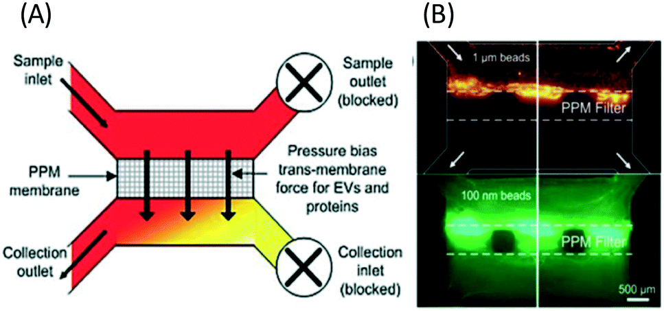 | ||
| Fig. 10 Microfluidic filtration of nanoparticles can be performed with a PPM filter with pressure-driven separation. (A) The PPM membrane passes particles smaller than the membrane pores to the collection outlet, while larger particles are retained in the sample channel. (B) shows the separation of 100 nm fluorescent beads from 1 μm diameter beads. Reproduced from ref. 48 with permission from The Royal Society of Chemistry. | ||
where ψp is the zeta potential of the particle, while ψs is the zeta potential of the channel surface, and D is the distance between the particles and the channel; κ is the inverse of the Debye length, which depends on the ionic concentration (ci) and ionic charge (zi), and is expressed by,

where NA is the Avogadro number, e is the electron charge, k is the Boltzmann constant and T is the absolute temperature. Nanoparticle trapping and separation using this electrostatic effect have been reported.167 Regtmeier et al. developed a microfluidic technique with overlapping EDL and separated 15 nm and 39 nm carboxylated polystyrene with a 525 nm constriction design by modulating the ionic concentration of the buffer.163 At low ionic concentrations, the electric double layer length is longer. This results in a higher electrostatic force that allows only smaller particles to pass through the constriction. As the ionic concentration increases, the EDL length is compressed, thereby allowing larger particles to pass through the constriction, as seen in Fig. 11A. In addition to the constriction design, a DLD pillar array with a small gap size shows a similar effect on particle separation. Zeming et al. used DLD with a 2 μm gap size to separate nanoparticles up to 50 nm in diameter using deionized water instead of ionic buffers, since this has the lowest ionic strength.53 The DLD effect alone cannot separate these nanoparticles, as the critical diameter of the DLD is 350 nm according to the formula. This phenomenon is caused by the electrostatic effect arising from the pillar's electric double layer force, which virtually increases the apparent diameter with an EDL distance (df-edl) of up to +800 nm in size in deionized water, as illustrated in Fig. 11B.53 Although this technique is passive and able to modulate separation easily by changing the buffer, it requires the use of low ionic strength buffer to perform nanoparticle separation, since most of the biomolecule samples, such as DNA, proteins, and exosomes, have individual ionic buffers that maintain their structures.

 | ||
| Fig. 11 (A) Nanoparticle separation with electrostatic sieving. In high ionic strength buffer, both large and small particles are able to pass through the constriction. In low ionic strength buffer, large particles cannot pass the ridge due to the strong electrostatic force from the electric double layer, while smaller particles still pass. (B) Microfluidic DLD electrostatic sieving. In DLD, the electrostatic double layer virtually increases the DLD pillar size with df-edl to reduce the critical diameter, resulting in enhanced separation in the presence of low ionic strength buffer solution but not in high ionic strength buffer solution. Reproduced from ref. 53 with permission from The Royal Society of Chemistry. | ||
 | ||
| Fig. 12 Microfluidic bacterial chemotaxis for autonomous separation of nanoparticles. (A) Channel designs for modulated diffusion of chemoattractant (B) selective attachment of nanoparticle to E. coli bacteria (C) chemotaxis migration of E. coli with attached nanoparticles. Reproduced from ref. 164 with permission from The Royal Society of Chemistry. | ||
Microfluidic nanoparticle separation applications
As microfluidic technology for nanoparticle separation is superior to conventional techniques, microfluidic techniques draw great interest for several potential applications, ranging from the purification of monodisperse nanoparticles for various industries, and waste water treatment, to nano-biomolecule separation, such as DNA, protein, virus, and exosome isolation.Biomolecule separation
The ability of microfluidics to separate nanoparticles can also be applied to the separation of biomolecules, such as DNA, proteins, viruses, and exosomes, which has significance in healthcare fields, such as medical diagnostics and therapeutics. These molecules and particles are more complex than synthetic nanoparticles because they can be easily degraded in unsuitable or harsh environments and do not have rigid forms. As it is more difficult to separate such molecules, current approaches to biomolecule separation still largely rely on external fields or immunological techniques, as they have the highest separation efficiency.Virus
A virus is an agent that causes disease, such as HIV, Ebola, Zika, and SARS. Detection of viral particles has important implications for medical diagnostics. However, isolation of a virus is difficult due to the diversity of virus sizes from small sizes of 20 nm to 400 nm, different shapes, surface charges, genome types, and protein contents.181 Furthermore, a virus sample is extracted from complex bodily fluids, such as blood, urine, and saliva, and requires purification from large cells or contaminants for accurate disease detection, as reported for HIV and dengue virus detection.182,183 Although ultrafiltration with a charge-based membrane is effective for viral particle separation, this technique is relatively expensive and needs additional elution steps, while still requiring the use of a suitable charge, buffer, and pH for the different types of viruses.184 Both passive and active microfluidic separation can be utilized to concentrate the virus and eliminate the contaminant in the samples. Wang et al. implemented passive microfluidic size-exclusion filtration to separate HIV virus from blood.185 Active microfluidic techniques for the enrichment of Sindbis viruses with a size of ∼70 nm has been achieved using iDEP in a sawtooth structured gradient.46 Acoustic microfluidics has also enabled dengue virus separation from cells with an efficiency of 70%.186 | ||
| Fig. 13 (A) ExoChip shows anti-CD63 immobilized in a microfluidic surface to capture exosome from serum. Reproduced from ref. 105 with permission from The Royal Society of Chemistry (B) trapping of exosomes with ciliated pillar structure on microfluidic device. Particles larger than cilia pores are not trapped on the cilia while particles much smaller than the pores pass through the structures. The cilia trap particles whose size matches the exosomes and SEM of the ciliated structure on pillar arrays. Reproduced from ref. 49 with permission from The Royal Society of Chemistry. (C) Acoustic forces in microfluidics are able to purify exosomes using a high-frequency field through IDT. Reprinted with permission from ref. 45 Copyright 2015 American Chemical Society. | ||
With label-free sieving methods, exosome separation with PPM-based membrane filtration from whole blood is demonstrated. The sieving technique can be performed with undiluted samples, such as whole blood, but it has a low recovery and sometimes there is damage to the vesicles.48 In addition to sieving, Wang et al. proposed a microfluidic trapping system with a ciliated micropost in a microfluidic device. The cilia on the pillars capture and immobilize the exosome, while larger structures flow around these microstructures. The immobilization of 83 nm lipid vesicles from 120 nm lipid vesicles and 500 nm nanoparticles was demonstrated.49 Although this technique can capture high purity exosomes from samples, it requires a long time for the separation, as the sample must be diluted to avoid device clogging. While several passive separations have been reported, there are fewer reports about active techniques for exosome separation. The active separation of exosomes from blood components using acoustic purification has been developed using a pair of interdigitated transducers (IDT), generating symmetric surface acoustic waves with a high ultrasound frequency to generate a cut-off size of 200 nm.45
Monodisperse nanoparticle production
Nanoparticle synthesis is currently shifting towards the modification of individual nanoparticles into higher-ordered structures and nanomaterials for various industrial applications.9 Metallic nanoparticles, such as gold, silver, and palladium, are utilized as sensors, solar cells, foods, drugs, paints, and other consumer products. Nanoparticle synthesis in these processes often yields polydispersed particles. Therefore, the control of size is crucial for achieving maximum nanoparticle performance, as the physical and chemical properties of these nanoparticles, such as aggregation tendency, depend on their size. For instance, monodispersed nanoparticles have been useful for achieving the maximum catalytic activity of a nanocatalyst in industrial reactions.196 The cytotoxicity of gold nanoparticles also depends on their size.197 Hence, the development of microfluidics to continuously purify monodispersed nanoparticles with high efficiency is beneficial for these industries. This application of microfluidics to purify nanoparticles for industrial purposes has not been implemented as it requires a large volume of sample, and hence high throughput separation is needed for this purpose.Environmental application
In addition to nanoparticle purification, microfluidic nanoparticle separation has the potential for environmental application, such as wastewater treatment and water desalination. Recently, nanoparticles have started to be used in consumer products, such as foods and cosmetics; therefore, nanoparticles will inevitably be found in domestic wastewater, and the presence of these nanosized particles could be hazardous for both health and environment. In addition to domestic waste, industrial nanoparticle waste must also be treated to avoid exposure of humans or the environment to nanoparticles, as traditional water treatment may not be enough to filter all of this ultra-small nanoparticle waste. For instance, silica nanoparticles are present in electronic chips and integrated circuits, resulting in industrial waste in China and Taiwan.10 Asymmetric FFF has been reported to separate nanoparticles for environmental applications to fractionate colloids, such as pollutants.198 Another application of microfluidics for environmental application is seawater desalination, such as that demonstrated by ICP, which is able to remove 99% of the salt from seawater with a low energy and cost.138Microfluidic nanoparticle separation challenges
The implementation of nanoparticle separation using microfluidics is still limited because there are several challenges that need to be addressed before it can be widely developed and used for real-world applications. These challenges include nanoparticle diffusion, limited throughput, and detection.where L is the channel length and Df is the diffusion coefficient of the particle, which depends on its size and shape. The Stokes–Einstein relationship expresses the diffusion coefficient as,

in which k is the Boltzmann constant, T is the absolute temperature, and μ is the dynamic viscosity of the fluid. The particle moves without significant diffusion if Pe ≫ 1 because the convection influences the movement of the particle much more than diffusion.156 While several techniques, such as field flow fractionation, employ Brownian motion to perform separation, the diffusion of nanoparticles mostly reduces the separation efficiency in other microfluidic techniques, especially in passive techniques where there is no external force that strongly opposes the Brownian motion. For a nanosized particle, the radius is of the order of 10−9, hence the Peclet number is higher compared to a micron-sized particle in the same channel. A nanoparticle diffusion effect is observed in electrostatic DLD for 50 nm size separation, inertial microfluidics in the separation of 200 nm, and ICP-induced separation of 100 nm nanoparticles, in which the spread of the particle is wider compared to the micron-sized particles, as seen in Fig. 14.53,137,145

 | ||
| Fig. 14 Wider separation spread caused by Brownian motion of nanoparticles in (A) electrostatic DLD of 50 nm and 190 nm nanoparticle size. Reproduced from ref. 53 with permission from The Royal Society of Chemistry (B) 500 and 200 nm in viscoelastic flow separation. Reproduced from ref. 145 with permission from The Royal Society of Chemistry, and (C) 100 nm nanoparticle size with ion concentration polarization. Reproduced from ref. 137 with permission from Nature Publishing Group. | ||
where R is the fluidic resistance, ΔP is the pressure difference and Q is the flow rate. In a simple rectangular channel, the resistance of a microfluidic device depends on the viscosity (μ), length (L), width (w) and height (h) of the device, and is expressed as199


Most microfluidic designs have dimensions of several to a hundred microns for length, width, and height, which results in a high resistance to fluidic movement. For several pressure-driven flow methods, especially passive ones, such as filtration and electrostatic sieving, used for nanoparticle separation, the channel has small pores (down to 2 μm size), which significantly increases their resistance to fluid flow.155 Other methods that are not driven by pressure differences, such as electrophoresis and electroosmosis, have a slower particle velocity and require high electric fields to increase the throughput. The current approach to increase the throughput is to stack the microfluidic devices in parallel. Inglis et al. were able to produce a flow rate of 1 mL min−1 by running six DLD devices in parallel for leucocyte enrichment.200 Khoo et al. also stacked three spiral microfluidic devices vertically to develop an ultra-high throughput for the detection and enrichment of circulating tumor cells.201
Recently, several innovations on detection techniques were able to achieve nanosized range detection. In optical methods, flow cytometry is one of the popular detection techniques for cells and microparticles as it is fast and accurate; however, conventional flow cytometry has a minimum detection limit of 200–500 nm with a resolution of 100–200 nm, and detection of smaller nanoparticles results in noise overlap from the system. Pospicalova et al. developed a dedicated flow cytometry, which is a modified flow cytometry with a different type of light scattering angle, to detect nanoparticles, and successfully performed the detection of fluorescently labeled exosomes and extracellular vesicles.213 Additionally, integration of microfluidics with micro-nuclear magnetic resonance (μ-NMR) for on-chip detection after separation has been reported to detect exosomes labeled with magnetic nanoparticles after the separation process.214 On top of detection with benchtop instruments, portable detection, such as using a smartphone, is recently an emerging field to detect micro/nanoparticles and bioparticles. Wei et al. demonstrated the imaging of a single 100 nm nanoparticle and a fluorescently labeled cytomegalovirus using a smartphone with a dongle developed for optical control of light excitation and emission, with embedded image processing for analysis.215
Conclusion
Nanoparticle separation plays an important role in many fields, in monodispersed nanoparticle production, water purification, and biomolecule separation. However, conventional methods to separate nanoparticles impose several limitations, such as not being continuous, and requiring multiple steps, a minimum sample volume, a specific buffer, and additional sample handling. Despite still being in the developing stages, both active and passive microfluidic separation techniques are starting to be implemented for nanoparticle and nano-biomolecule separation, as they can overcome these limitations. This brings more opportunities, especially in the medical diagnostic field, for simple, continuous, and faster separation of biomolecules. However, there is a need to explore more possibilities and more prototypes to prove the concept of nanoparticle separation in microfluidics. Microfluidics for nanoparticle separation is more likely to advance towards label-free passive separation, as this is a simpler technique without external fields or surface markers for separation. However, further research is needed to overcome the Brownian motion of nanoparticles in the microchannel to increase the separation efficiency. The application of microfluidics for large industrial nanoparticle separation also still poses a challenge, as improvement in throughput is required to process large sample volumes. Finally, each microfluidic technique has its own advantages and drawbacks for nanoparticle separation, and there is no single technique that can be tailored to all the sample needs.Acknowledgements
We would like to acknowledge the scholarship from NUS Graduate School for integrative Science and Engineering and funding support from Ministry of Education Academic Research Fund, Singapore (AcRF: R-397-000-183-112).References
- B. Sun, E. Marx and N. C. Greenham, Nano Lett., 2003, 3, 961–963 CrossRef CAS.
- L. Yuan, X.-H. Lu, X. Xiao, T. Zhai, J. Dai, F. Zhang, B. Hu, X. Wang, L. Gong and J. Chen, ACS Nano, 2011, 6, 656–661 CrossRef PubMed.
- S. Raj, S. Jose, U. Sumod and M. Sabitha, J. Pharm. BioAllied Sci., 2012, 4, 186 CrossRef PubMed.
- F. von der Kammer, S. Legros, T. Hofmann, E. H. Larsen and K. Loeschner, TrAC, Trends Anal. Chem., 2011, 30, 425–436 CrossRef CAS.
- S. Gelperina, K. Kisich, M. D. Iseman and L. Heifets, Am. J. Respir. Crit. Care Med., 2005, 172, 1487–1490 CrossRef PubMed.
- K. E. Petersen, E. Manangon, J. L. Hood, S. A. Wickline, D. P. Fernandez, W. P. Johnson and B. K. Gale, Anal. Bioanal. Chem., 2014, 406, 7855–7866 CrossRef CAS PubMed.
- L. Zhang, F. Gu, J. Chan, A. Wang, R. Langer and O. Farokhzad, Clin. Pharmacol. Ther., 2008, 83, 761–769 CrossRef CAS PubMed.
- M.-C. Daniel and D. Astruc, Chem. Rev., 2004, 104, 293–346 CrossRef CAS PubMed.
- B. Kowalczyk, I. Lagzi and B. A. Grzybowski, Curr. Opin. Colloid Interface Sci., 2011, 16, 135–148 CrossRef CAS.
- Y. Liu, M. Tourbin, S. Lachaize and P. Guiraud, Chemosphere, 2013, 92, 681–687 CrossRef CAS PubMed.
- G. Bystrzejewska-Piotrowska, J. Golimowski and P. L. Urban, Waste Manage., 2009, 29, 2587–2595 CrossRef CAS PubMed.
- S. Choi, M. Goryll, L. Y. M. Sin, P. K. Wong and J. Chae, Microfluid. Nanofluid., 2011, 10, 231–247 CrossRef CAS.
- D. M. Whiley, S. Bialasiewicz, C. Bletchly, C. E. Faux, B. Harrower, A. R. Gould, S. B. Lambert, G. R. Nimmo, M. D. Nissen and T. P. Sloots, J. Clin. Virol., 2009, 45, 203–204 CrossRef CAS PubMed.
- A. S. Azmi, B. Bao and F. H. Sarkar, Cancer Metastasis Rev., 2013, 32, 623–642 CrossRef CAS PubMed.
- P. A. Gonzales, T. Pisitkun, J. D. Hoffert, D. Tchapyjnikov, R. A. Star, R. Kleta, N. S. Wang and M. A. Knepper, J. Am. Soc. Nephrol., 2009, 20, 363–379 CrossRef CAS PubMed.
- Y. Mori, KONA Powder Part. J., 2015, 32, 102–114 CrossRef.
- J. A. Davis, D. W. Inglis, K. J. Morton, D. A. Lawrence, L. R. Huang, S. Y. Chou, J. C. Sturm and R. H. Austin, Proc. Natl. Acad. Sci. U. S. A., 2006, 103, 14779–14784 CrossRef CAS PubMed.
- D. W. Inglis, N. Herman and G. Vesey, Biomicrofluidics, 2010, 4, 024109 CrossRef PubMed.
- H. W. Hou, A. A. S. Bhagat, A. G. L. Chong, P. Mao, K. S. W. Tan, J. Han and C. T. Lim, Lab Chip, 2010, 10, 2605–2613 RSC.
- H. W. Hou, M. E. Warkiani, B. L. Khoo, Z. R. Li, R. A. Soo, D. S.-W. Tan, W.-T. Lim, J. Han, A. A. S. Bhagat and C. T. Lim, Sci. Rep., 2013, 3, 1259 Search PubMed.
- Z. Wu, B. Willing, J. Bjerketorp, J. K. Jansson and K. Hjort, Lab Chip, 2009, 9, 1193–1199 RSC.
- A. A. S. Bhagat, H. Bow, H. W. Hou, S. J. Tan, J. Han and C. T. Lim, Med. Biol. Eng. Comput., 2010, 48, 999–1014 Search PubMed.
- C. W. Shields IV, C. D. Reyes and G. P. López, Lab Chip, 2015, 15, 1230–1249 RSC.
- P. Sajeesh and A. K. Sen, Microfluid. Nanofluid., 2014, 17, 1–52 CrossRef.
- A. Lenshof and T. Laurell, Chem. Soc. Rev., 2010, 39, 1203–1217 RSC.
- C. Duan, W. Wang and Q. Xie, Biomicrofluidics, 2013, 7, 026501 CrossRef PubMed.
- X. Sun, S. M. Tabakman, W. S. Seo, L. Zhang, G. Zhang, S. Sherlock, L. Bai and H. Dai, Angew. Chem., Int. Ed., 2009, 48, 939–942 CrossRef CAS PubMed.
- V. Sharma, K. Park and M. Srinivasarao, Proc. Natl. Acad. Sci. U. S. A., 2009, 106, 4981–4985 CrossRef CAS PubMed.
- O. Akbulut, C. R. Mace, R. V. Martinez, A. A. Kumar, Z. Nie, M. R. Patton and G. M. Whitesides, Nano Lett., 2012, 12, 4060–4064 CrossRef CAS PubMed.
- F.-K. Liu, F.-H. Ko, P.-W. Huang, C.-H. Wu and T.-C. Chu, J. Chromatogr. A, 2005, 1062, 139–145 CrossRef CAS.
- X. Xu, K. K. Caswell, E. Tucker, S. Kabisatpathy, K. L. Brodhacker and W. A. Scrivens, J. Chromatogr. A, 2007, 1167, 35–41 CrossRef CAS PubMed.
- M. Hanauer, S. Pierrat, I. Zins, A. Lotz and C. Sönnichsen, Nano Lett., 2007, 7, 2881–2885 CrossRef CAS PubMed.
- H. Zorbas, Bioanalytics: Methods on Molecular Biotechnology and Modern Biotechnology, Wiley, New York, 2010 Search PubMed.
- E. Heftmann, Chromatography: Fundamentals and applications of chromatography and related differential migration methods-Part B: Applications, Elsevier, 2004 Search PubMed.
- G.-T. Wei and F.-K. Liu, J. Chromatogr. A, 1999, 836, 253–260 CrossRef CAS.
- S. Benfer, P. Arki and G. Tomandl, Adv. Eng. Mater., 2004, 6, 495–500 CrossRef CAS.
- E. Krieg, H. Weissman, E. Shirman, E. Shimoni and B. Rybtchinski, Nat. Nanotechnol., 2011, 6, 141–146 CrossRef CAS PubMed.
- C.-L. Wang, M. Fang, S.-H. Xu and Y.-P. Cui, Langmuir, 2009, 26, 633–638 CrossRef PubMed.
- S. R. Saunders and C. B. Roberts, Nanotechnology, 2009, 20, 475605 CrossRef CAS PubMed.
- J. N. Duggan and C. B. Roberts, J. Phys. Chem. C, 2014, 118, 14595–14605 CAS.
- B. H. Wunsch, J. T. Smith, S. M. Gifford, C. Wang, M. Brink, R. L. Bruce, R. H. Austin, G. Stolovitzky and Y. Astier, Nat. Nanotechnol., 2016, 134 Search PubMed , advance online publication.
- H. Bruus, Lab Chip, 2012, 12, 1014–1021 RSC.
- J. Zhang, S. Yan, D. Yuan, G. Alici, N.-T. Nguyen, M. E. Warkiani and W. Li, Lab Chip, 2016, 16, 10–34 RSC.
- H. Song, J. M. Rosano, Y. Wang, C. J. Garson, B. Prabhakarpandian, K. Pant, G. J. Klarmann, A. Perantoni, L. M. Alvarez and E. Lai, Lab Chip, 2015, 15, 1320–1328 RSC.
- K. Lee, H. Shao, R. Weissleder and H. Lee, ACS Nano, 2015, 9, 2321–2327 CrossRef CAS PubMed.
- J. Ding, R. M. Lawrence, P. V. Jones, B. G. Hogue and M. A. Hayes, Analyst, 2016, 141, 1997–2008 RSC.
- T. M. Squires and S. R. Quake, Rev. Mod. Phys., 2005, 77, 977 CrossRef CAS.
- R. T. Davies, J. Kim, S. C. Jang, E.-J. Choi, Y. S. Gho and J. Park, Lab Chip, 2012, 12, 5202–5210 RSC.
- Z. Wang, H.-J. Wu, D. Fine, J. Schmulen, Y. Hu, B. Godin, J. X. Zhang and X. Liu, Lab Chip, 2013, 13, 2879–2882 RSC.
- J. McGrath, M. Jimenez and H. Bridle, Lab Chip, 2014, 14, 4139–4158 RSC.
- W. Zhang, in Nanomaterial, Springer, 2014, pp. 19–43 Search PubMed.
- Y. Kazoe, K. Mawatari, Y. Sugii and T. Kitamori, Anal. Chem., 2011, 83, 8152–8157 CrossRef CAS PubMed.
- K. K. Zeming, N. V. Thakor, Y. Zhang and C.-H. Chen, Lab Chip, 2016, 16, 75–85 RSC.
- A. Sánchez-Iglesias, M. Grzelczak, T. Altantzis, B. Goris, J. Pérez-Juste, S. Bals, G. Van Tendeloo, S. H. Donaldson, B. F. Chmelka, J. N. Israelachvili and L. M. Liz-Marzán, ACS Nano, 2012, 6, 11059–11065 CrossRef PubMed.
- S. H. Donaldson, A. Røyne, K. Kristiansen, M. V. Rapp, S. Das, M. A. Gebbie, D. W. Lee, P. Stock, M. Valtiner and J. Israelachvili, Langmuir, 2015, 31, 2051–2064 CrossRef CAS PubMed.
- M. Napoli, P. Atzberger and S. Pennathur, Microfluid. Nanofluid., 2011, 10, 69–80 CrossRef CAS.
- C. Zhao and X. Cheng, Biomicrofluidics, 2011, 5, 032004 CrossRef PubMed.
- J. C. Giddings, Science, 1993, 260, 1456–1465 CAS.
- A. I. Lao, D. Trau and I.-M. Hsing, Anal. Chem., 2002, 74, 5364–5369 CrossRef CAS PubMed.
- T. Shendruk and G. Slater, J. Chromatogr. A, 2012, 1233, 100–108 CrossRef CAS PubMed.
- H. J. Sant and B. K. Gale, J. Chromatogr. A, 2006, 1104, 282–290 CrossRef CAS PubMed.
- N. Narayanan, A. Saldanha and B. K. Gale, Lab Chip, 2006, 6, 105–114 RSC.
- A. De Momi and J. R. Lead, Sci. Total Environ., 2008, 405, 317–323 CrossRef CAS PubMed.
- A. De Momi and J. R. Lead, Environ. Sci. Technol., 2006, 40, 6738–6743 CrossRef CAS PubMed.
- B. Schmidt, K. Loeschner, N. Hadrup, A. Mortensen, J. J. Sloth, C. Bender Koch and E. H. Larsen, Anal. Chem., 2011, 83, 2461–2468 CrossRef CAS PubMed.
- L. Calzolai, D. Gilliland, C. P. Garcìa and F. Rossi, J. Chromatogr. A, 2011, 1218, 4234–4239 CrossRef CAS PubMed.
- H. Hagendorfer, R. Kaegi, M. Parlinska, B. Sinnet, C. Ludwig and A. Ulrich, Anal. Chem., 2012, 84, 2678–2685 CrossRef CAS PubMed.
- K. Loeschner, J. Navratilova, S. Legros, S. Wagner, R. Grombe, J. Snell, F. von der Kammer and E. H. Larsen, J. Chromatogr. A, 2013, 1272, 116–125 CrossRef CAS PubMed.
- J. Heroult, V. Nischwitz, D. Bartczak and H. Goenaga-Infante, Anal. Bioanal. Chem., 2014, 406, 3919–3927 CrossRef CAS PubMed.
- D. Müller, S. Cattaneo, F. Meier, R. Welz and A. J. de Mello, Front. Chem., 2015, 3, 45 Search PubMed.
- F. A. Messaud, R. D. Sanderson, J. R. Runyon, T. Otte, H. Pasch and S. K. R. Williams, Prog. Polym. Sci., 2009, 34, 351–368 CrossRef CAS.
- A. Wysocki, C. P. Royall, R. G. Winkler, G. Gompper, H. Tanaka, A. van Blaaderen and H. Lowen, Soft Matter, 2009, 5, 1340–1344 RSC.
- D. H. Sharp, Phys. D, 1984, 12, 3–18 CrossRef.
- B. H. Kwon, H. H. Kim, J. H. Park, D. H. Yoon, M. C. Kim, S. Sheard, K. Morten and J. S. Go, Jpn. J. Appl. Phys., 2013, 52, 026601 CrossRef.
- P. Arosio, T. Müller, L. Mahadevan and T. P. Knowles, Nano Lett., 2014, 14, 2365–2371 CrossRef CAS PubMed.
- J. B. Ha, Y. K. Bahk, S. H. Yoon, J. H. Lee, E. H. Jeong, S. Y. Yoon, T. Arakawa, J. S. Ko, B. S. Shin, K. C. Kim, J. S. Boo, S. Shoji and J. S. Go, International Solid-State Sensors, Actuators and Microsystems Conference, 2007, pp. 927–930, DOI:10.1109/SENSOR.2007.4300283.
- A. Ashkin, Phys. Rev. Lett., 1970, 24, 156 CrossRef CAS.
- K. S. Lee, J. H. Jung, B. H. Ha, H. J. Sung and S. S. Kim, Appl. Phys. Lett., 2014, 105, 071908 CrossRef.
- K. S. Lee, S. Y. Yoon, K. H. Lee, S. B. Kim, H. J. Sung and S. S. Kim, J. Opt. Soc. Am. B, 2012, 29, 407–414 CrossRef CAS.
- Y. Yang, Y. Shi, L. Chin, J. Zhang, D. Tsai and A. Liu, The 17th International Conference on Transducers & Eurosensors XXVII, 2013, pp. 2122–2125 Search PubMed.
- Y. Shi, S. Xiong, L. Chin, M. Ren and A. Liu, IEEE 27th International Conference on Micro Electro Mechanical Systems (MEMS), 2014, pp. 1015–1018 Search PubMed.
- H. Zhang and K.-K. Liu, J. R. Soc., Interface, 2008, 5, 671–690 CrossRef CAS PubMed.
- M. Hejazian and N.-T. Nguyen, Lab Chip, 2015, 15, 2998–3005 RSC.
- M. A. Gijs, F. Lacharme and U. Lehmann, Chem. Rev., 2009, 110, 1518–1563 CrossRef PubMed.
- A. Munir, Z. Zhu, J. Wang and H. S. Zhou, IET Nanobiotechnol., 2014, 8, 102–110 CrossRef CAS PubMed.
- A. Munir, J. Wang, Z. Li and H. S. Zhou, Microfluid. Nanofluid., 2010, 8, 641–652 CrossRef CAS.
- B. Le Drogoff, L. Clime and T. Veres, Microfluid. Nanofluid., 2008, 5, 373–381 CrossRef CAS.
- S. H. S. Lee, T. A. Hatton and S. A. Khan, Microfluid. Nanofluid., 2011, 11, 429–438 CrossRef CAS.
- G. D. Chen, C. J. Alberts, W. Rodriguez and M. Toner, Anal. Chem., 2009, 82, 723–728 CrossRef PubMed.
- H. C. Tekin and M. A. Gijs, Lab Chip, 2013, 13, 4711–4739 RSC.
- L. Ren, Y. Chen, P. Li, Z. Mao, P.-H. Huang, J. Rufo, F. Guo, L. Wang, J. P. McCoy and S. J. Levine, Lab Chip, 2015, 15, 3870–3879 RSC.
- X. Ding, S.-C. S. Lin, M. I. Lapsley, S. Li, X. Guo, C. Y. Chan, I. K. Chiang, L. Wang, J. P. McCoy and T. J. Huang, Lab Chip, 2012, 12, 4228–4231 RSC.
- L. Y. Yeo and J. R. Friend, Annu. Rev. Fluid Mech., 2014, 46, 379–406 CrossRef.
- X. Ding, Z. Peng, S.-C. S. Lin, M. Geri, S. Li, P. Li, Y. Chen, M. Dao, S. Suresh and T. J. Huang, Proc. Natl. Acad. Sci. U. S. A., 2014, 111, 12992–12997 CrossRef CAS PubMed.
- P. Li, Z. Mao, Z. Peng, L. Zhou, Y. Chen, P.-H. Huang, C. I. Truica, J. J. Drabick, W. S. El-Deiry and M. Dao, Proc. Natl. Acad. Sci. U. S. A., 2015, 112, 4970–4975 CrossRef CAS PubMed.
- X. Ding, P. Li, S.-C. S. Lin, Z. S. Stratton, N. Nama, F. Guo, D. Slotcavage, X. Mao, J. Shi, F. Costanzo and T. J. Huang, Lab Chip, 2013, 13, 3626–3649 RSC.
- G. Destgeer, K. H. Lee, J. H. Jung, A. Alazzam and H. J. Sung, Lab Chip, 2013, 13, 4210–4216 RSC.
- G. Destgeer, B. H. Ha, J. Park, J. H. Jung, A. Alazzam and H. J. Sung, Phys. Procedia, 2015, 70, 34–37 CrossRef CAS.
- G. Destgeer, B. H. Ha, J. H. Jung and H. J. Sung, Lab Chip, 2014, 14, 4665–4672 RSC.
- J. Shi, H. Huang, Z. Stratton, Y. Huang and T. J. Huang, Lab Chip, 2009, 9, 3354–3359 RSC.
- D. J. Collins, T. Alan and A. Neild, Lab Chip, 2014, 14, 1595–1603 RSC.
- D. J. Collins, A. Neild and Y. Ai, Lab Chip, 2016, 16, 471–479 RSC.
- M. Wiklund, R. Green and M. Ohlin, Lab Chip, 2012, 12, 2438–2451 RSC.
- A. R. Guerreiro, I. Chianella, E. Piletska, M. J. Whitcombe and S. A. Piletsky, Biosens. Bioelectron., 2009, 24, 2740–2743 CrossRef CAS PubMed.
- S. S. Kanwar, C. J. Dunlay, D. M. Simeone and S. Nagrath, Lab Chip, 2014, 14, 1891–1900 RSC.
- T. H. Nguyen, R. Pei, M. Stojanovic and Q. Lin, Sens. Actuators, B, 2011, 155, 58–66 CrossRef CAS.
- M. Ebara, J. M. Hoffman, A. S. Hoffman, P. S. Stayton and J. J. Lai, Langmuir, 2013, 29, 5388–5393 CrossRef CAS PubMed.
- X. Huang, Y. Zhu, X. Zhang, Z. Bao, D. Y. Lei, W. Yu, J. Dai and Y. Wang, Sens. Actuators, B, 2016, 222, 106–111 CrossRef CAS.
- O. D. Velev, S. Gangwal and D. N. Petsev, Annu. Rep. Prog. Chem., Sect. C: Phys. Chem., 2009, 105, 213–246 RSC.
- L. Trapiella-Alfonso, F. d'Orlyé and A. Varenne, Anal. Bioanal. Chem., 2016, 408, 2669–2675 CrossRef CAS PubMed.
- F.-K. Liu, Y.-Y. Lin and C.-H. Wu, Anal. Chim. Acta, 2005, 528, 249–254 CrossRef CAS.
- M. Bouri, R. Salghi, M. Algarra, M. Zougagh and A. Rios, RSC Adv., 2015, 5, 16672–16677 RSC.
- B. Franze and C. Engelhard, Anal. Chem., 2014, 86, 5713–5720 CrossRef CAS PubMed.
- R. T. Turgeon and M. T. Bowser, Anal. Bioanal. Chem., 2009, 394, 187–198 CrossRef CAS PubMed.
- D. Kohlheyer, G. A. J. Besselink, S. Schlautmann and R. B. M. Schasfoort, Lab Chip, 2006, 6, 374–380 RSC.
- H. Jeon, Y. Kim and G. Lim, Sci. Rep., 2016, 6, 19911 CrossRef CAS PubMed.
- H. Ranchon, R. Malbec, V. Picot, A. Boutonnet, P. Terrapanich, P. Joseph, T. Leichlé and A. Bancaud, Lab Chip, 2016, 16, 1243–1253 RSC.
- B. Çetin and D. Li, Electrophoresis, 2011, 32, 2410–2427 CrossRef PubMed.
- T. Z. Jubery, S. K. Srivastava and P. Dutta, Electrophoresis, 2014, 35, 691–713 CrossRef CAS PubMed.
- S. K. Srivastava, J. L. Baylon-Cardiel, B. H. Lapizco-Encinas and A. R. Minerick, J. Chromatogr. A, 2011, 1218, 1780–1789 CrossRef CAS PubMed.
- E. B. Cummings, IEEE Eng. Med. Biol. Mag., 2003, 22, 75–84 CrossRef PubMed.
- E. B. Cummings, IEEE Eng. Med. Biol. Mag., 2003, 22, 75–84 CrossRef PubMed.
- B. H. Lapizco-Encinas and M. Rito-Palomares, Electrophoresis, 2007, 28, 4521–4538 CrossRef CAS PubMed.
- S. Dash, S. Mohanty, S. Pradhan and B. Mishra, J. Taiwan Inst. Chem. Eng., 2015, 58, 39–48 CrossRef.
- C. Chen, J. Skog, C.-H. Hsu, R. T. Lessard, L. Balaj, T. Wurdinger, B. S. Carter, X. O. Breakefield, M. Toner and D. Irimia, Lab Chip, 2010, 10, 505–511 RSC.
- S. Dash and S. Mohanty, Electrophoresis, 2014, 35, 2656–2672 CrossRef CAS PubMed.
- M. Viefhues, R. Eichhorn, E. Fredrich, J. Regtmeier and D. Anselmetti, Lab Chip, 2012, 12, 485–494 RSC.
- K. F. Hoettges, M. B. McDonnell and M. P. Hughes, Electrophoresis, 2014, 35, 467–473 CrossRef CAS PubMed.
- B. H. Lapizco-Encinas, B. A. Simmons, E. B. Cummings and Y. Fintschenko, Anal. Chem., 2004, 76, 1571–1579 CrossRef CAS PubMed.
- B. G. Hawkins and B. J. Kirby, Electrophoresis, 2010, 31, 3622–3633 CrossRef CAS PubMed.
- D. Chen, H. Du and C. Y. Tay, Nanoscale Res. Lett., 2010, 5, 55–60 CrossRef CAS PubMed.
- S. J. Kim, Y.-A. Song and J. Han, Chem. Soc. Rev., 2010, 39, 912–922 RSC.
- M. Kim, M. Jia and T. Kim, Analyst, 2013, 138, 1370–1378 RSC.
- S. H. Ko, Y.-A. Song, S. J. Kim, M. Kim, J. Han and K. H. Kang, Lab Chip, 2012, 12, 4472–4482 RSC.
- S. J. Kim, Y.-C. Wang, J. H. Lee, H. Jang and J. Han, Phys. Rev. Lett., 2007, 99, 044501 CrossRef PubMed.
- S. J. Kim, L. D. Li and J. Han, Langmuir, 2009, 25, 7759–7765 CrossRef CAS PubMed.
- H. Jeon, H. Lee, K. H. Kang and G. Lim, Sci. Rep., 2013, 3, 3483 Search PubMed.
- S. J. Kim, S. H. Ko, K. H. Kang and J. Han, Nat. Nanotechnol., 2010, 5, 297–301 CrossRef CAS PubMed.
- R. A. Rica and M. Z. Bazant, Phys. Fluids, 2010, 22, 112109 CrossRef.
- M. Boettcher, S. Schmidt, A. Latz, M. Jaeger, M. Stuke and C. Duschl, J. Phys.: Condens. Matter, 2011, 23, 324101 CrossRef CAS PubMed.
- M. Felten, W. Staroske, M. S. Jaeger, P. Schwille and C. Duschl, Electrophoresis, 2008, 29, 2987–2996 CrossRef CAS PubMed.
- M. N. Mohtar, K. F. Hoettges and M. P. Hughes, Electrophoresis, 2014, 35, 345–351 CrossRef CAS PubMed.
- N. G. Green and H. Morgan, J. Phys. D: Appl. Phys., 1998, 31, L25 CrossRef CAS.
- A. A. S. Bhagat, S. S. Kuntaegowdanahalli and I. Papautsky, Microfluid. Nanofluid., 2009, 7, 217–226 CrossRef CAS.
- J. Y. Kim, S. W. Ahn, S. S. Lee and J. M. Kim, Lab Chip, 2012, 12, 2807–2814 RSC.
- S. S. Kuntaegowdanahalli, A. A. S. Bhagat, G. Kumar and I. Papautsky, Lab Chip, 2009, 9, 2973–2980 RSC.
- A. A. S. Bhagat, S. S. Kuntaegowdanahalli and I. Papautsky, Lab Chip, 2008, 8, 1906–1914 RSC.
- Z. Liu, F. Huang, J. Du, W. Shu, H. Feng, X. Xu and Y. Chen, Biomicrofluidics, 2013, 7, 011801 CrossRef PubMed.
- N. Tottori, T. Nisisako, J. Park, Y. Yanagida and T. Hatsuzawa, Biomicrofluidics, 2016, 10, 014125 CrossRef.
- S. H. Holm, J. P. Beech, M. P. Barrett and J. O. Tegenfeldt, Lab Chip, 2011, 11, 1326–1332 RSC.
- S. Ranjan, K. K. Zeming, R. Jureen, D. Fisher and Y. Zhang, Lab Chip, 2014, 14, 4250–4262 RSC.
- L. R. Huang, E. C. Cox, R. H. Austin and J. C. Sturm, Science, 2004, 304, 987–990 CrossRef CAS PubMed.
- D. W. Inglis, J. A. Davis, R. H. Austin and J. C. Sturm, Lab Chip, 2006, 6, 655–658 RSC.
- K. Loutherback, K. Chou, J. Newman, J. Puchalla, R. Austin and J. Sturm, Microfluid. Nanofluid., 2010, 9, 1143–1149 CrossRef.
- K. K. Zeming, T. Salafi, C.-H. Chen and Y. Zhang, Sci. Rep., 2016, 6, 22934 CrossRef CAS PubMed.
- S. M. Santana, M. A. Antonyak, R. A. Cerione and B. J. Kirby, Biomed. Microdevices, 2014, 16, 869–877 CrossRef CAS PubMed.
- J. C. Sturm, E. C. Cox, B. Comella and R. H. Austin, Interface Focus, 2014, 4, 20140054 CrossRef PubMed.
- H. N. Joensson, M. Uhlén and H. A. Svahn, Lab Chip, 2011, 11, 1305–1310 RSC.
- X. Chen, D. Cui and J. Chen, Electrophoresis, 2009, 30, 3168–3173 CrossRef CAS PubMed.
- L. Amato, Y. Gu, N. Bellini, S. M. Eaton, G. Cerullo and R. Osellame, Lab Chip, 2012, 12, 1135–1142 RSC.
- E. Ban, Y. S. Yoo and E. J. Song, Talanta, 2015, 141, 15–20 CrossRef CAS PubMed.
- A. A. S. Bhagat, S. S. Kuntaegowdanahalli, D. D. Dionysiou and I. Papautsky, MOEMS-MEMS 2008 Micro and Nanofabrication, 2008, pp. 688600–688611 Search PubMed.
- J. Regtmeier, J. Käsewieter, M. Everwand and D. Anselmetti, J. Sep. Sci., 2011, 34, 1180–1183 CrossRef CAS PubMed.
- S. Suh, M. A. Traore and B. Behkam, Lab Chip, 2016, 16, 1254–1260 RSC.
- D. Li, Electrokinetics in microfluidics, Academic Press, 2004 Search PubMed.
- S. H. Donaldson Jr, S. Das, M. A. Gebbie, M. Rapp, L. C. Jones, Y. Roiter, P. H. Koenig, Y. Gizaw and J. N. Israelachvili, ACS Nano, 2013, 7, 10094–10104 CrossRef PubMed.
- M. Krishnan, N. Mojarad, P. Kukura and V. Sandoghdar, Nature, 2010, 467, 692–695 CrossRef CAS PubMed.
- J. Wu, X. Wu and F. Lin, Lab Chip, 2013, 13, 2484–2499 RSC.
- M. A. Traore and B. Behkam, J. Micromech. Microeng., 2013, 23, 085014 CrossRef.
- R. Ashton, C. Padala and R. S. Kane, Curr. Opin. Biotechnol., 2003, 14, 497–504 CrossRef CAS PubMed.
- N. Minc, C. Fütterer, K. D. Dorfman, A. Bancaud, C. Gosse, C. Goubault and J.-L. Viovy, Anal. Chem., 2004, 76, 3770–3776 CrossRef CAS PubMed.
- M. Viefhues, J. Regtmeier and D. Anselmetti, Analyst, 2013, 138, 186–196 RSC.
- R. H. Austin, Electrophoresis, 2002, 23, 3496–3503 CrossRef.
- Y. Chen, E. S. Abrams, T. C. Boles, J. N. Pedersen, H. Flyvbjerg, R. H. Austin and J. C. Sturm, Phys. Rev. Lett., 2015, 114, 198303 CrossRef PubMed.
- J. Wen, J. Albrecht, E. W. Wilker, M. B. Yaffe and K. F. Jensen, Proceedings of the 12th International Conference on Miniaturized Systems for Chemistry and Life Sciences (μTAS2008), pp. 492–495 Search PubMed.
- C. Herzog, E. Poehler, A. J. Peretzki, S. M. Borisov, D. Aigner, T. Mayr and S. Nagl, Lab Chip, 2016, 16, 1565–1572 RSC.
- H. Ding, X. Li, X. Lv, J. Xu, X. Sun, Z. Zhang, H. Wang and Y. Deng, Analyst, 2012, 137, 4482–4489 RSC.
- C. F. Ivory and S. K. Srivastava, Electrophoresis, 2011, 32, 2323–2330 CrossRef CAS PubMed.
- D. Kim, J. Shim, H.-S. Chuang and K. C. Kim, J. Mech. Sci. Technol., 2014, 28, 2629–2636 CrossRef.
- A. Nakano, F. Camacho-Alanis, T.-C. Chao and A. Ros, Biomicrofluidics, 2012, 6, 034108 CrossRef PubMed.
- E. Sollier and D. Di Carlo, Microfluidic Technologies for Human Health, 2012, p. 311 Search PubMed.
- T. R. Poloni, A. S. Oliveira, H. L. Alfonso, L. R. Galvão, A. A. Amarilla, D. F. Poloni, L. T. Figueiredo and V. H. Aquino, Virol. J., 2010, 7, 1 CrossRef PubMed.
- A. Y. Yamamoto, M. M. Mussi-Pinhata, L. J. Marin, R. M. Brito, P. F. C. Oliveira and T. B. Coelho, J. Clin. Virol., 2006, 36, 228–230 CrossRef CAS PubMed.
- M. R. Karim, E. R. Rhodes, N. Brinkman, L. Wymer and G. S. Fout, Appl. Environ. Microbiol., 2009, 75, 2393–2399 CrossRef CAS PubMed.
- S. Wang, D. Sarenac, M. H. Chen, S.-H. Huang, F. F. Giguel, D. R. Kuritzkes and U. Demirci, Int. J. Nanomed., 2012, 7, 5019–5028 Search PubMed.
- E. J. Fong, A. C. Johnston, T. Notton, S.-Y. Jung, K. A. Rose, L. S. Weinberger and M. Shusteff, Analyst, 2014, 139, 1192–1200 RSC.
- S. A. Melo, H. Sugimoto, J. T. O'Connell, N. Kato, A. Villanueva, A. Vidal, L. Qiu, E. Vitkin, L. T. Perelman and C. A. Melo, Cancer Cell, 2014, 26, 707–721 CrossRef CAS PubMed.
- S. Keller, J. Ridinger, A.-K. Rupp, J. W. Janssen and P. Altevogt, J. Transl. Med., 2011, 9, 86 CrossRef CAS PubMed.
- G. Raposo and W. Stoorvogel, J. Cell Biol., 2013, 200, 373–383 CrossRef CAS PubMed.
- M. He, J. Crow, M. Roth, Y. Zeng and A. K. Godwin, Lab Chip, 2014, 14, 3773–3780 RSC.
- R. J. Lobb, M. Becker, S. Wen Wen, C. S. F. Wong, A. P. Wiegmans, A. Leimgruber and A. Möller, J. Extracell. Vesicles, 2015, 4, 27031 Search PubMed.
- A. H. Ng, K. Choi, R. P. Luoma, J. M. Robinson and A. R. Wheeler, Anal. Chem., 2012, 84, 8805–8812 CrossRef CAS PubMed.
- A. Liga, A. Vliegenthart, W. Oosthuyzen, J. Dear and M. Kersaudy-Kerhoas, Lab Chip, 2015, 15, 2388–2394 RSC.
- C. Théry, L. Zitvogel and S. Amigorena, Nat. Rev. Immunol., 2002, 2, 569–579 Search PubMed.
- Z. Zhao, Y. Yang, Y. Zeng and M. He, Lab Chip, 2016, 489–496 RSC.
- R. Narayanan and M. A. El-Sayed, Nano Lett., 2004, 4, 1343–1348 CrossRef CAS.
- Y. Pan, S. Neuss, A. Leifert, M. Fischler, F. Wen, U. Simon, G. Schmid, W. Brandau and W. Jahnen-Dechent, Small, 2007, 3, 1941–1949 CrossRef CAS PubMed.
- S. Dubascoux, F. Von Der Kammer, I. Le Hécho, M. P. Gautier and G. Lespes, J. Chromatogr. A, 2008, 1206, 160–165 CrossRef CAS PubMed.
- L. A. Godwin, K. S. Deal, L. D. Hoepfner, L. A. Jackson and C. J. Easley, Anal. Chim. Acta, 2013, 758, 101–107 CrossRef CAS PubMed.
- D. W. Inglis, M. Lord and R. E. Nordon, J. Micromech. Microeng., 2011, 21, 054024 CrossRef.
- B. L. Khoo, M. E. Warkiani, D. S.-W. Tan, A. A. S. Bhagat, D. Irwin, D. P. Lau, A. S. Lim, K. H. Lim, S. S. Krisna and W.-T. Lim, PLoS One, 2014, 9, e99409 Search PubMed.
- S. K. R. Williams, J. R. Runyon and A. A. Ashames, Anal. Chem., 2010, 83, 634–642 CrossRef PubMed.
- J. D. Robertson, L. Rizzello, M. Avila-Olias, J. Gaitzsch, C. Contini, M. S. Magoń, S. A. Renshaw and G. Battaglia, Sci. Rep., 2016, 6, 27494 CrossRef CAS PubMed.
- M. T. Blom, E. Chmela, R. E. Oosterbroek, R. Tijssen and A. van den Berg, Anal. Chem., 2003, 75, 6761–6768 CrossRef CAS PubMed.
- H. Shintaku, H. Nishikii, L. A. Marshall, H. Kotera and J. G. Santiago, Anal. Chem., 2014, 86, 1953–1957 CrossRef CAS PubMed.
- D. G. Rackus, M. H. Shamsi and A. R. Wheeler, Chem. Soc. Rev., 2015, 44, 5320–5340 RSC.
- A. Dawoud, T. Kawaguchi, Y. Markushin, M. D. Porter and R. Jankowiak, Sens. Actuators, B, 2006, 120, 42–50 CrossRef CAS.
- A. D. Bani-Yaseen, T. Kawaguchi, A. K. Price, C. T. Culbertson and R. Jankowiak, Anal. Bioanal. Chem., 2011, 399, 519–524 CrossRef CAS PubMed.
- J. S. Mellors, W. A. Black, A. G. Chambers, J. A. Starkey, N. A. Lacher and J. M. Ramsey, Anal. Chem., 2013, 85, 4100–4106 CrossRef CAS PubMed.
- C. Wang, A. B. Jemere and D. J. Harrison, Electrophoresis, 2010, 31, 3703–3710 CrossRef CAS PubMed.
- X. Wang, L. Yi, N. Mukhitov, A. M. Schrell, R. Dhumpa and M. G. Roper, J. Chromatogr. A, 2015, 1382, 98–116 CrossRef CAS PubMed.
- D. Gao, H. Liu, Y. Jiang and J.-M. Lin, Lab Chip, 2013, 13, 3309–3322 RSC.
- V. Pospichalova, J. Svoboda, Z. Dave, A. Kotrbova, K. Kaiser, D. Klemova, L. Ilkovics, A. Hampl, I. Crha and E. Jandakova, J. Extracell. Vesicles, 2015, 4, 25530 Search PubMed.
- H. Shao, J. Chung, L. Balaj, A. Charest, D. D. Bigner, B. S. Carter, F. H. Hochberg, X. O. Breakefield, R. Weissleder and H. Lee, Nat. Med., 2012, 18, 1835–1840 CrossRef CAS PubMed.
- Q. Wei, H. Qi, W. Luo, D. Tseng, S. J. Ki, Z. Wan, Z. N. Göröcs, L. A. Bentolila, T.-T. Wu and R. Sun, ACS Nano, 2013, 7, 9147–9155 CrossRef CAS PubMed.
| This journal is © The Royal Society of Chemistry 2017 |