 Open Access Article
Super impact absorbing bio-alloys from inedible plants†
Jumpei
Kawada
 *a,
Masayuki
Kitou
b,
Makoto
Mouri
a,
Yuichi
Kato
a,
Yoshihide
Katagiri
a,
Mitsumasa
Matsushita
a,
Toshiyuki
Ario
b,
Osamu
Kitou
b and
Arimitsu
Usuki
a
aToyota Central R&D laboratories, Inc., 41-1 Yokomichi, Nagakute, Aichi 480-1192, Japan. E-mail: jumpei-kawada@mosk.tytlabs.co.jp
bToyota Boshoku Corporation, 88 Kanayama, Kamekubi, Toyota, Aichi 470-0395, Japan
First published on 11th August 2017
Abstract
Injection molded bio-alloys based on polyamide 11 (PA11), 100% bio-based plastics from inedible plants, and polypropylene (PP) mixed with the maleic anhydride-modified ethylene-butene rubber copolymer (m-EBR) were prepared using a twin-screw extruder. The mechanical properties and morphologies of the bio-alloys were investigated using flexural tests, Charpy notched impact tests, field emission-scanning electron microscopy (FE-SEM), Raman spectroscopy, and transmission electron microscopy (TEM). The bio-alloy had a flexural modulus of 1090 ± 20 MPa and a Charpy notched impact strength of 98 ± 5 kJ m−2, which is superior to that of polycarbonates. The FE-SEM observations revealed that the bio-alloy has a unique “salami-like structure in a co-continuous phase”, and the TEM observations showed that some m-EBR formed 10 to 20 nm wide continuous interphases between the PP and PA11 matrices. Continuous rubber interphases played an important role in enhancing the impact strength. The bio-alloys exhibited good rigidity and excellent impact strength, making them feasible for applications in automobiles and other industries.
Nowadays, there are several challenges to tackle, such as the ongoing climate change1,2 and dwindling supply of oil resources.3 If these challenges are not addressed, then the outcome may be fairly bleak, and the establishment of a carbon neutral and sustainable society will be unlikely. Thus, the use of efficient and environmentally benign technologies for the utilization of renewable resources has become indispensable. Bio-based plastics, such as those derived from plant-based or renewable resources, will perhaps develop into one of the key technologies4–7 to address these challenges. From the perspective of materials scientists, if bio-based plastics are increasingly used in industries such as the automobile industry, reduction of the steadily increasing greenhouse gases will become feasible, as the production of plastics requires much less energy than that of metals and ceramics.8 Furthermore, the utilization of bio-based plastics (low density) instead of metals (high density) will lead to a reduction in the weight of automobiles, which will result in improved fuel efficiency and an associated reduction in CO2 emission. Lately, automobiles are gradually moving from gas-powered vehicles (internal combustion engine) toward electric-powered ones. Consequently, the required physical and mechanical properties for vehicles' materials are changing. It is thus essential to produce low-density, high-performance bio-based plastics with high impact strength to prevent serious injuries from traffic collisions due to unforeseen circumstances.
Although some bio-based plastics such as poly(lactic acid)9 and poly(hydroxy alkanoate)s10,11 are already on the market due to significant progress and tremendous achievements, the share of bio-based or renewable plastics in the plastics market is low (<5%),12 and these plastics are not employed to a significant extent in the automobile or electric industries. Recently, cellulose nanofibers (CNF), another promising material, have been studied intensively.13–16 CNF can be used as nanosize fillers in a polymer matrix since they have excellent modulus and tensile strength,17,18 but they cannot be utilized as a thermoplastic. Polymer alloys have added different characteristics to the original polymers, and improved the mechanical and physical properties of polymers.19,20 Numerous studies on synthetic polymer alloys and blends have been reported,19–25 which have led to an understanding of the polymer toughening mechanism, including crazing, cavitation, and shear yielding.22,26–33 Nevertheless, there are still few bio-based plastics or bio-alloys in the automobile and electrical industries.
Vegetable oils are historically and presently one of the most important renewable feedstocks. The annual global production of vegetable oils amounted to approximately 140 million tons in 2009 and 2010, and the production of castor oil increased by 38% from 1999 to 2008.34 Castor beans are a non-food resource because they contain the highly toxic ricin. Polyamide 11 (PA11) was used in this study because it is a completely bio-based plastic made from the castor bean plant which thus absorbs CO2 during cultivation. Therefore, the use of PA11 is advantageous because the amount of CO2 emission is not increased, whereas the production of other polyamides (PA) from petroleum resources does increase CO2 emissions. The total energy consumption required to produce PA11 is less than that required to produce petroleum-based PA. For bio-alloys, polypropylene (PP) was selected as the counterpart of PA11 because Braskem expects a 30 kton per year of green polypropylene plant to go onstream as soon as bio-based propylene is available from bioethanol8 and PP is one of the most abundant plastics in the world. Although the PP/PA11 bio-alloy is currently produced as a partially bio-based plastic, it is possible to be produced as a 100% bio-alloy in the near future.
Recently, bio-based alloys have been studied as green materials35–37 because the processing method, so-called melt blending, is an organic solvent-free process. The research to date on the PP/PA11 bio-alloy by Wang et al. has revealed that the PP/PA11 bio-alloy has a dispersed phase morphology and that the dispersed phase size of PA11 is dependent on the amount of maleated ethylene-propylene-diene rubber.38,39 Fu et al. simulated a PP/PA11 blend by atomistic molecular dynamics and mesoscopic dynamics simulations and predicted that the PP/PA11 blend had a phase separation structure or a co-continuous structure, depending on the PP/PA11 ratio40 as well as the PP/PA6 alloy.41 We have reported “salami” and finer “nano-salami” structures of PP/PA11 bio-alloys that have significantly enhanced the Charpy notched impact strength without a large reduction in the stiffness of the bio-alloys.42 Nanotechnology has played an extremely important role in the design of polymer alloys. Therefore, the purpose of this research is to create bio-alloys with good stiffness and high toughness by controlling the bio-alloy morphology at the nanometre scale, especially considering applications in the automobile or electrical industries.
Morphological control of bio-alloy by PP/PA11 ratio
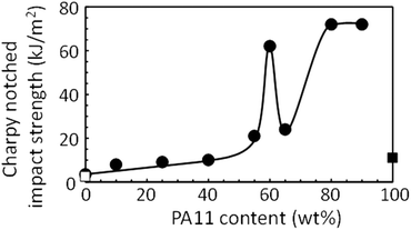
The controlled morphologies of PP/PA11 bio-alloys exhibited salami or nano-salami structures.42 To develop further morphology changes and potentially different mechanical properties, bio-alloys with different PP/PA11 ratios and a constant amount of reactive compatibilizer (10 wt%) were prepared as listed in Table 1. Previous studies showed that PP/PA11 bio-alloys had poor mechanical properties without appropriate compatibilizers.39,42 The mechanical properties of injection molded samples were analyzed, and the results are shown in Table 1.| Sample | Proportion (wt%) | Mechanical properties | |||
|---|---|---|---|---|---|
| PP | PA11 | m-EBRa | Flexural modulus (MPa) | Charpy notched impact strength (kJ m−2) | |
| a Maleic anhydride-modified ethylene-butene rubber copolymer. | |||||
| #1 | 100 | 0 | 0 | 1480 ± 30 | 2.5 ± 0.2 |
| #2 | 0 | 100 | 0 | 1310 ± 30 | 11 ± 2 |
| #3 | 90 | 0 | 10 | 1200 ± 10 | 3.5 ± 0.5 |
| #4 | 80 | 10 | 10 | 1050 ± 10 | 8.0 ± 0.3 |
| #5 | 65 | 25 | 10 | 1120 ± 20 | 9.1 ± 0.6 |
| #6 | 50 | 40 | 10 | 1150 ± 10 | 10 ± 0.3 |
| #7 | 35 | 55 | 10 | 1000 ± 10 | 21 ± 0.3 |
| #8 | 30 | 60 | 10 | 950 ± 10 | 62 ± 2 |
| #9 | 25 | 65 | 10 | 940 ± 20 | 24 ± 1 |
| #10 | 10 | 80 | 10 | 870 ± 10 | 72 ± 1 |
| #11 | 0 | 90 | 10 | 870 ± 30 | 72 ± 1 |
The flexural moduli of these bio-alloy samples decreased from 1200 MPa to 870 MPa when the amount of PA11 was increased because the flexural modulus of PA11 with the reactive compatibilizer is low. However, the trend of the Charpy notched impact strength for these PP/PA11 bio-alloys was quite different from that of the flexural moduli, as shown in Fig. 1, when the PA11 content was increased. It should be noted that the Charpy notched impact strength with a PA11 content of 60 wt% was extremely high.
To understand the unusual trend of the Charpy notched impact strength with respect to the PP/PA11 ratio, the morphologies of the bio-alloys were observed using field emission-scanning electron microscopy (FE-SEM), and the results are shown in Fig. 2. The FE-SEM image of sample #5 in Fig. 2 shows a typical salami structure where PP was a matrix and PA11 was a dispersed phase including dispersed subdomains of m-EBR.42 As the proportion of PA11 was increased, the size of the salami structure was enlarged, as represented by sample #6. On the other hand, when PA was added at 60 wt%, such as in sample #8, PP and PA11 both formed independent matrices to generate a co-continuous phase in which the PP matrix had PA11 salami structures with m-EBR or PP dispersed subdomains, and the PA11 matrix had PP salami structures with m-EBR or PA11 dispersed subdomains. This is a novel structure that has salami structures in each continuous phase. Since Ide and Hasegawa reported a versatile route to enhance the physical properties of PA,21 extensive studies have been conducted for the purpose of toughening PA. The relationship between the morphology and the mechanical properties has since been studied in the blends of PP and PA.40,41,43–47 Nonetheless, the unique phenomenon observed here in PP/PA has not yet been reported and not predicted by computer simulation.40,41 As the proportion of PA11 was increased to more than 60 wt%, the morphology was altered to be a PA11 matrix, i.e., a phase inversion occurred, as shown in sample #9. In sample #11, PA11 and m-EBR were mixed finely at the nanometre scale. These results suggest that salami structures in a co-continuous phase lead to significant improvements in the mechanical properties of PP/PA11 bio-alloys.
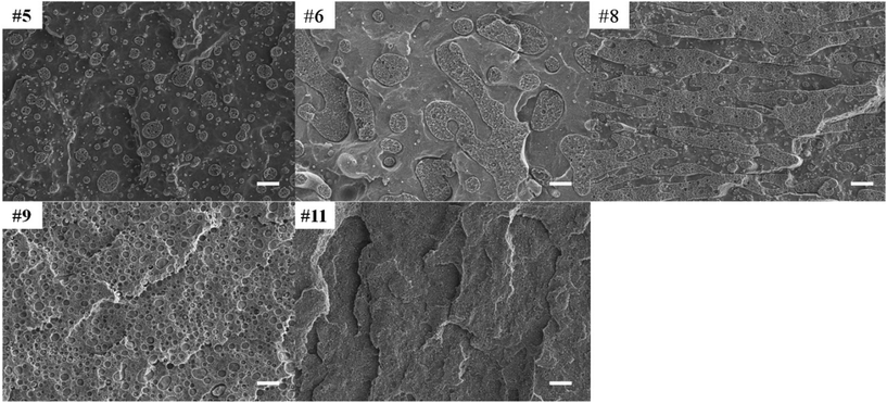 | ||
| Fig. 2 FE-SEM images of freeze-fracture surfaces of the injection molded test pieces subjected to oxygen plasma treatment for 60 s. The sample numbers correspond to those in Table 1. The scale bars represent 2 μm. | ||
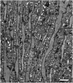
Transmission electron microscopy (TEM) and atomic force microscopy measurements have provided evidence that the interphase between a matrix and dispersed phases in a salami structure is m-EBR.42 Sample #8 was investigated using a TEM technique with a stain for rubbers as shown in Fig. 3, and the interphases were observed as dark layers between the PP and PA11 matrices. These results indicate that m-EBR was located in the interphases, and Fig. 3 shows that m-EBR formed continuous phases with widths of approximately 10 to 20 nm.
These continuous rubber interphases account for the significant improvement in the impact resistance and are the reason why bio-alloys with 70% PA11 did not have high Charpy notched impact strength, because the bio-alloy did not have these continuous interphases due to the phase inversion.
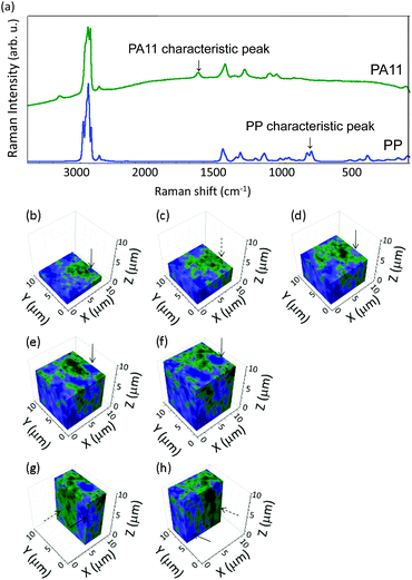
To confirm that the co-continuous phase was present in all three dimensions, sample #8 was examined using Raman spectroscopy. Fig. 4(a) shows the Raman spectra of PP and PA11. The PP spectrum shows a characteristic peak at 840 cm−1, indicative of ρ(CH2) vibrations, while the PA11 spectrum has a characteristic peak at 1640 cm−1, which is attributed to the amide I band and is indicative of C![[double bond, length as m-dash]](https://www.rsc.org/images/entities/char_e001.gif) O stretching. Consequently, the presence of both components can be distinguished by assessing these two peaks. A three-dimensional analysis of sample #8 based on its Raman spectrum is presented in Fig. 4(b–h), where the PP and PA11 regions are coloured blue and green, respectively. The arrow in Fig. 4(b) indicates a PP region, and there was PA11 at the same position except for the z position in Fig. 4(c) shown by the broken arrow when the sample was measured just above 2.4 μm in the z axis direction of Fig. 4(b). PP appeared again in Fig. 4(d), (e) and (f), as indicated by the arrow, when the sample was observed from the positive z direction, at z = 5.1, 7.5, and 9.9 μm, respectively. When sample #8 was observed from different faces, as in Fig. 4(g) and (h), continuous PP matrices at the arrows and continuous PA11 matrices at the broken arrows were detected.
O stretching. Consequently, the presence of both components can be distinguished by assessing these two peaks. A three-dimensional analysis of sample #8 based on its Raman spectrum is presented in Fig. 4(b–h), where the PP and PA11 regions are coloured blue and green, respectively. The arrow in Fig. 4(b) indicates a PP region, and there was PA11 at the same position except for the z position in Fig. 4(c) shown by the broken arrow when the sample was measured just above 2.4 μm in the z axis direction of Fig. 4(b). PP appeared again in Fig. 4(d), (e) and (f), as indicated by the arrow, when the sample was observed from the positive z direction, at z = 5.1, 7.5, and 9.9 μm, respectively. When sample #8 was observed from different faces, as in Fig. 4(g) and (h), continuous PP matrices at the arrows and continuous PA11 matrices at the broken arrows were detected.
The Raman data revealed that PP and PA11 form an independent continuous matrix. In this analysis, the spatial resolution was on the order of 1 μm, such that the salami structures, which are usually less than 1 μm, could not be detected in the co-continuous phase structure.
Mechanism for impact strength with salami structures in a co-continuous phase structure
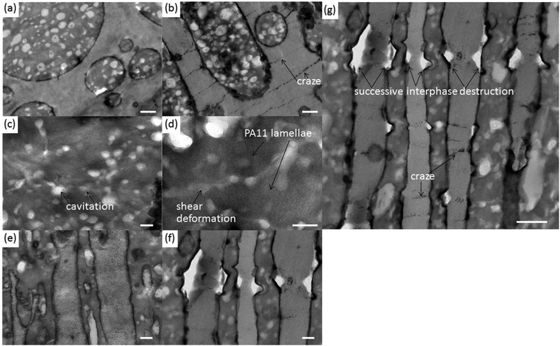
The bio-alloys exhibit excellent impact strength when the salami structures are formed in the co-continuous phase structure. Sample #8 was examined before and after the Charpy notched impact test in detail using the TEM staining technique to investigate the mechanism for the improvement in impact strength. Several important traces, such as crazes, cavitations and shear deformation, to improve the impact strength were detected, as shown in Fig. 5. No crazing was observed in the PP matrix (Fig. 5(a)) before the Charpy notched impact test; however, there were many crazes, formed by the absorption of energy, with widths of approximately 10 nm and lengths from a few hundred nanometres to several micrometres (Fig. 5(b)) after the Charpy notched impact test. In addition, PA regions were significantly changed between Fig. 5(a) and (b); cavitations and shearing deformation were observed in PA11 regions at high magnification, as shown in Fig. 5(c) and (d), respectively. The cavitations were sometimes integrated with one another and the size of a cavitation was ca. 50 nm. Shearing deformation by absorption of the impact energy was observed. Crazing, cavitations and shearing deformation have been previously reported for polymer blends and polymer alloys.26,27,30–33 PA11 lamellae are clearly evident in Fig. 5(d), which indicates that some PA11 was well crystallized. In the salami structures in the co-continuous phases, there is another phenomenon that enhances the impact strength: successive interphase destruction, as shown in Fig. 5(f) and (g). No evidence of impact energy absorption was observed in Fig. 5(e) before the Charpy notched impact test, whereas there was evidence of successive interphase destruction along the direction of the impact energy, as shown in Fig. 5(f). It is important to note that this structure had a continuous rubber interphase between the PP and PA11 matrices, and the continuous rubber interphases play a major role in the absorption of the impact energy. When the impact energy was too high to be absorbed by the continuous rubber interphase, the impact energy was propagated and the adjacent matrices attempted to absorb the energy, as evidenced by crazes in PP or cavitations and shearing deformation in PA11. Excess energy that the matrix could not absorb would be absorbed by the adjacent rubber interphase, as shown in Fig. 5(g). Therefore, the interphases were successively destroyed by the absorption of impact energy.The fracture surface of sample #8 was quite unique. The surface occasionally left evidence of ductile behaviour, as shown in Fig. 6. The materials were stretched well at the interface, vertical to the fracture surface, which indicates plastic deformation, and is evidence that a significant amount of impact energy was absorbed during the stretching of the material.
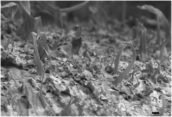 | ||
| Fig. 6 FE-SEM image of the sample #8 fracture surface after the Charpy notched impact test. The scale bar represents 5 μm. | ||
The morphologically controlled bio-alloy with salami structures in a co-continuous phase structure has superior mechanical properties, i.e. excellent impact resistance with a good flexural modulus. Such properties are challenging to achieve, especially both high rigidity and high impact resistance, because these properties are mutually exclusive. This enhancement of the mechanical properties is most certainly due to the structure. PP regions retain a good flexural modulus and PA11, which has end-groups bonded to m-EBR,42 is attributed to the improvement of the Charpy notched impact strength through mechanisms such as the formation of cavitations and shearing deformation. In addition, continuous rubber interphases between the PP and PA11 matrices, whose width is only 10 to 20 nm, play a key role in enhancing the Charpy notched impact strength because the rubber interphase can absorb the impact energy.
One-step procedure
We attempted to prepare a PP/PA11 bio-alloy (PP![[thin space (1/6-em)]](https://www.rsc.org/images/entities/char_2009.gif) :
:![[thin space (1/6-em)]](https://www.rsc.org/images/entities/char_2009.gif) PA11
PA11![[thin space (1/6-em)]](https://www.rsc.org/images/entities/char_2009.gif) :
:![[thin space (1/6-em)]](https://www.rsc.org/images/entities/char_2009.gif) m-EBR = 30
m-EBR = 30![[thin space (1/6-em)]](https://www.rsc.org/images/entities/char_2009.gif) :
:![[thin space (1/6-em)]](https://www.rsc.org/images/entities/char_2009.gif) 60
60![[thin space (1/6-em)]](https://www.rsc.org/images/entities/char_2009.gif) :
:![[thin space (1/6-em)]](https://www.rsc.org/images/entities/char_2009.gif) 10 wt%) with a single process using a production model twin-screw extruder. The extruder has a relatively less retention time and high shear force due to a fast extrusion rate and large diameter, which affects polymer degradation and leads to good compounding of the polymers compared with small type twin-screw extruders that require two-step melt-blending to prepare such bio-alloys. A long retention time above the melting point with high shear force affects the molecular chain cut; therefore, it is important to control the retention time, mixing temperature, and shear force. Consequently, the bio-alloy obtained by an optimized one-step procedure had excellent mechanical properties, such as a flexural modulus of 1090 ± 20 MPa and a Charpy notched impact strength of 98 ± 5 kJ m−2 at room temperature. The Charpy notched impact strength for the bio-alloy was much better than that of polycarbonate (PC), which is one of the toughest plastics. Accordingly, this bio-alloy is potentially applicable to plastic automobile parts that require high impact strength, for instance door trim. The morphology obtained in the test pieces also had salami structures in a co-continuous phase structure.
10 wt%) with a single process using a production model twin-screw extruder. The extruder has a relatively less retention time and high shear force due to a fast extrusion rate and large diameter, which affects polymer degradation and leads to good compounding of the polymers compared with small type twin-screw extruders that require two-step melt-blending to prepare such bio-alloys. A long retention time above the melting point with high shear force affects the molecular chain cut; therefore, it is important to control the retention time, mixing temperature, and shear force. Consequently, the bio-alloy obtained by an optimized one-step procedure had excellent mechanical properties, such as a flexural modulus of 1090 ± 20 MPa and a Charpy notched impact strength of 98 ± 5 kJ m−2 at room temperature. The Charpy notched impact strength for the bio-alloy was much better than that of polycarbonate (PC), which is one of the toughest plastics. Accordingly, this bio-alloy is potentially applicable to plastic automobile parts that require high impact strength, for instance door trim. The morphology obtained in the test pieces also had salami structures in a co-continuous phase structure.
Conclusion
PP/PA11 bio-alloys were fabricated by an organic solvent-free green process. Reactive processing in a twin-screw extruder enabled the control of the morphology of the bio-alloy interphase at the nanoscale. The results of this investigation provide essential insights into how structures and nano-order interphases affect the mechanical properties of polymer alloys. Bio-alloys may be able to overcome synthetic polymers in some specific areas, such as parts that require high impact strength because the bio-alloy presented here has superior impact strength and moldability compared to synthetic high impact plastics because typical high impact plastics were too viscous to be used for large injection molding systems. Next-generation bio-based plastics should be produced from inedible biomass and should contribute to the establishment of a more carbon neutral and sustainable society. Therefore, it is time for further developments in this field to solve global environmental problems. Using the approach of nano-morphological control, the results presented here may facilitate the development of high-performance bio-based plastics that can compete with traditional synthetic plastics.Conflicts of interest
There are no conflicts to declare.Acknowledgements
The authors are grateful to Dr Hironari Sano for TEM observations and helpful discussions.References
- S. R. Loarie, P. B. Duffy, H. Hamilton, G. P. Asner, C. B. Field and D. D. Ackerly, Nature, 2009, 462, 1052–1055 CrossRef CAS PubMed.
- IPCC. Climate Change 2013: The Physical Science Basis. Contribution of Working Group I to the Fifth Assessment Report of the Intergovernmental Panel on Climate Change (Cambridge Univ. Press, 2013).
- Statistical Review of World Energy, BP, 2016.
- D. R. Dodds and R. A. Gross, Science, 2007, 318, 1250–1251 CrossRef CAS PubMed.
- R. A. Sheldon, Chem. Soc. Rev., 2012, 41, 1437–1451 RSC.
- G. Pierre, Chem. Soc. Rev., 2012, 41, 1538–1558 RSC.
- C. O. Tuck, E. Pérez, I. T. Horváth, R. A. Sheldon and M. Poliakoff, Science, 2012, 337, 695–699 CrossRef CAS PubMed.
- R. Mülhaupt, Macromol. Chem. Phys., 2013, 214, 159–174 CrossRef.
- L.-T. Lim, R. Auras and M. Rubino, Prog. Polym. Sci., 2008, 33, 820–852 CrossRef CAS.
- R. W. Lenz and R. H. Marchessault, Biomacromolecules, 2005, 6, 1–8 CrossRef CAS PubMed.
- T. Iwata, Angew. Chem., Int. Ed., 2015, 54, 3210–3215 CrossRef CAS PubMed.
- K. Yao and C. Tang, Macromolecules, 2013, 46, 1689–1712 CrossRef CAS.
- H. Yano, J. Sugiyama, A. N. Nakagaito, M. Nogi, T. Matsumura, M. Hikita and K. Handa, Adv. Mater., 2005, 17, 153–155 CrossRef CAS.
- T. Saito, Y. Nishiyama, J.-L. Putaux, M. Vignon and A. Isogai, Biomacromolecules, 2007, 7, 1687–1691 CrossRef PubMed.
- M. Henriksson, L. A. Berglund, P. Isaksson, T. Lindström and T. Nishino, Biomacromolecules, 2008, 9, 1579–1585 CrossRef CAS PubMed.
- Y. Habibi, L. A. Lucia and O. J. Rojas, Chem. Rev., 2010, 110, 3479–3500 CrossRef CAS PubMed.
- D. T. Page, F. El-Hosseiny and K. Winker, Nature, 1971, 229, 252–253 CrossRef CAS PubMed.
- A. K. Bledzki and J. Gassan, Prog. Polym. Sci., 1999, 24, 221–274 CrossRef CAS.
- L. A. Utracki, Polymer Alloys and Blends, Hanser Gardner Publications, 1989 Search PubMed.
- A. S. Hay, J. Polym. Sci., Part A: Polym. Chem., 1998, 36, 505–517 CrossRef CAS.
- F. Ide and A. Hasegawa, J. Appl. Polym. Sci., 1974, 18, 963–947 CrossRef CAS.
- S. Wu, Polymer, 1985, 26, 1855–1863 CrossRef CAS.
- S. Wu, Polym. Eng. Sci., 1987, 27, 335–343 CAS.
- L. A. Utracki and Z. H. Shi, Polym. Eng. Sci., 1992, 32, 1824–1833 CAS.
- T. Inoue, Prog. Polym. Sci., 1995, 20, 119–153 CrossRef CAS.
- A. M. Donald and E. J. Kramer, J. Appl. Polym. Sci., 1982, 27, 3729–3741 CrossRef CAS.
- A. J. Kinloch, S. J. Shaw and D. A. Tod, Polymer, 1983, 24, 1341–1354 CrossRef CAS.
- A. Margolina and S. Wu, Polymer, 1988, 29, 2170–2173 CrossRef CAS.
- S. Wu, J. Appl. Polym. Sci., 1988, 35, 549–561 CrossRef CAS.
- S. Wu, Polym. Eng. Sci., 1990, 30, 753–761 CAS.
- A. Lazzeri and C. Bucknall, J. Mater. Sci., 1993, 28, 6799–6808 CrossRef CAS.
- O. K. Muratoglu, A. S. Argon and R. E. Cohen, Polymer, 1995, 36, 2143–2152 CrossRef CAS.
- A. S. Argon and R. E. Cohen, Polymer, 2003, 44, 6013–6032 CrossRef CAS.
- U. Biermann, U. Bornscheuer, M. A. R. Meier, J. O. Metzger and H. J. Schäfer, Angew. Chem., Int. Ed., 2011, 50, 3854–3871 CrossRef CAS PubMed.
- L. Jiang, M. P. Wolcott and J. Zhang, Biomacromolecules, 2006, 7, 199–207 CrossRef CAS PubMed.
- T. Lebarbé, E. Grau, B. Gadenne, C. Alfos and H. Cramail, ACS Sustainable Chem. Eng., 2015, 3, 283–292 CrossRef.
- S. Spinella, J. Cai, C. Samuel, J. Zhu, S. A. McCallum, Y. Habibi, J.-M. Raquez, P. Dubois and R. A. Grossa, Biomacromolecules, 2015, 16, 1818–1826 CrossRef CAS PubMed.
- B. Wang, G. Hu and L. Wei, J. Appl. Polym. Sci., 2008, 107, 3013–3022 CrossRef CAS.
- B.-B. Wang, L.-X. Wei and G.-S. Hu, J. Appl. Polym. Sci., 2008, 110, 1344–1350 CrossRef CAS.
- Y. Fu, L. Liao, Y. Lan, L. Yang, L. Mei, Y. Liu and S. Hu, J. Mol. Struct., 2012, 1012, 113–118 CrossRef CAS.
- H. F. Guo, S. Packirisamy, N. V. Gvozdic and D. J. Meier, Polymer, 1997, 38, 785–794 CrossRef CAS.
- J. Kawada, M. Kitou, M. Mouri, T. Mitsuoka, T. Araki, C.-H. Lee, T. Ario, O. Kitou and A. Usuki, ACS Sustainable Chem. Eng., 2016, 4, 2158–2164 CrossRef CAS.
- B.-R. Liang, J. L. White, J. E. Spruiell and B. C. Goswamiet, J. Appl. Polym. Sci., 1983, 28, 2011–2032 CrossRef CAS.
- S. J. Park, B. K. Kim and H. M. Jeong, Eur. Polym. J., 1990, 26, 131–136 CrossRef CAS.
- R. Holstimiettinen, J. Seppälä and O. T. Ikkala, Polym. Eng. Sci., 1992, 32, 868–877 CAS.
- A. Gozález-Montiel, H. Keskkula and D. R. Paul, Polymer, 1995, 24, 4587–4603 CrossRef.
- A. Wilkinson, M. L. Clemens and V. M. Harding, Polymer, 2004, 45, 5239–5249 CrossRef CAS.
Footnote |
| † Electronic supplementary information (ESI) available. See DOI: 10.1039/c7gc01842h |
| This journal is © The Royal Society of Chemistry 2017 |

