 Open Access Article
Creative Commons Attribution 3.0 Unported Licence
Hydrogen storage using a hot pressure swing reactor†
H.
Jorschick
 a,
P.
Preuster
 b,
S.
Dürr
 b,
A.
Seidel
b,
K.
Müller
c,
A.
Bösmann
b and
P.
Wasserscheid
b,
A.
Seidel
b,
K.
Müller
c,
A.
Bösmann
b and
P.
Wasserscheid
 *ab
*ab
aForschungszentrum Jülich GmbH, Helmholtz Institute Erlangen-Nürnberg for Renewable Energy (IEK-11), Egerlandstr. 3, 91058 Erlangen, Germany. E-mail: peter.wasserscheid@fau.de
bLehrstuhl für Chemische Reaktionstechnik, Friedrich-Alexander-Universität Erlangen-Nürnberg, Egerlandstr. 3, D-91058 Erlangen, Germany
cLehrstuhl für Thermische Verfahrenstechnik, Friedrich-Alexander-Universität Erlangen-Nürnberg, Egerlandstr. 3, D-91058 Erlangen, Germany
First published on 9th June 2017
Abstract
Our contribution demonstrates that hydrogen storage in stationary Liquid Organic Hydrogen Carrier (LOHC) systems becomes much simpler and significantly more efficient if both, the LOHC hydrogenation and the LOHC dehydrogenation reaction are carried out in the same reactor using the same catalyst. The finding that the typical dehydrogenation catalyst for hydrogen release from perhydro dibenzyltoluene (H18-DBT), Pt on alumina, turns into a highly active and very selective dibenzyltoluene hydrogenation catalyst at temperatures above 220 °C paves the way for our new hydrogen storage concept. Herein, hydrogenation of H0-DBT and dehydrogenation of H18-DBT is carried out at the same elevated temperature between 290 and 310 °C with hydrogen pressure being the only variable for shifting the equilibrium between hydrogen loading and release. We demonstrate that the heat of hydrogenation can be provided at a temperature level suitable for effective dehydrogenation catalysis. Combined with a heat storage device of appropriate capacity or a high pressure steam system, this heat could be used for dehydrogenation.
Broader contextHydrogen storage in form of Liquid Organic Hydrogen Carrier (LOHC) systems offers the opportunity for infrastructure-compatible energy storage on a very large scale and over long periods of time without losses. Our contribution demonstrates that for stationary hydrogen storage the technology becomes much simpler and significantly more efficient if both, the LOHC hydrogenation and the LOHC dehydrogenation reaction are carried out in the same reactor using the same catalyst. It is shown that a Pt on alumina catalyst promotes the hydrogenation of dibenzyltoluene (H0-DBT) as well as the dehydrogenation of perhydro dibenzyltoluene (H18-DBT) in the temperature range of 290 to 310 °C with hydrogen pressure being the only variable for shifting the equilibrium between hydrogen loading and release. This way of operation safes investment for catalyst and reactor, drastically increases the hydrogen storage dynamics, and opens novel opportunities for heat integration and catalyst regeneration. |
1. Introduction
In recent times energy storage via Liquid Organic Hydrogen Carrier (LOHC) systems has gained significant attention.1,2 This is mainly due to the fact that hydrogen storage in form of liquids offers the opportunity for energy storage on a very large scale and over long periods of time without losses. In fact, the storage scale and time is only limited by the size of the respective tanks and the technical availability of the respective LOHC compounds. In contrast to other power-to-X concepts, LOHC systems enable energy storage without binding or releasing CO2 or N2 from or to the atmosphere.Among the different LOHC compounds that have been considered, pure hydrocarbon systems offer the advantages of low cost and full compatibility with the existing infrastructure for liquid fuels. However, all pure hydrocarbon LOHC systems are characterised by a relatively high heat of dehydrogenation, e.g. 68 kJ mol−1-H2 for hydrogen release from methylcyclohexane3 or 65 kJ mol−1-H2 for hydrogen release from perhydro dibenzyltoluene.4 As a consequence, catalytic hydrogen release requires a relatively high amount of heat input at temperatures typically above 250 °C. At these high temperatures, heat integration with heat losses from the subsequent hydrogen utilization step is only possible if the latter operates at a very high temperature, such as in the cases of hydrogen combustion in a solid oxide fuel cell, in a turbine or in a combustion engine. The fact that considerable amounts of heat are needed at energy-lean times (where typically hydrogen release from LOHC would be operated to provide energy) has been seen by many authors as the main drawback of energy storage in form of LOHC systems.5 Attempts to overcome this problem have been so far mainly directed towards the development of LOHC compounds with lower heats of dehydrogenation, such as e.g., carbazole-6 or quinaldine-based7 systems, albeit their thermal stability and technical availability are significantly less favourable.
In the present contribution we demonstrate that – at least for stationary energy storage applications – the required heat for the dehydrogenation of a pure hydrocarbon, hydrogen-rich LOHC compound can be provided from the previous hydrogenation of the respective aromatic LOHC compound. This requires (a) catalytic hydrogenation and dehydrogenation to take place in the same hot reactor, and (b) aromatic hydrogenation to be carried out at a slightly higher temperature than alicyclic dehydrogenation to allow storage of hydrogenation heat in a suitable heat storage system for its reuse in subsequent dehydrogenation.
The established, state-of-the-art stationary LOHC storage setup applies separate hydrogenation and dehydrogenation reactors with the hydrogenation reactor operating at low temperature/high pressure and the dehydrogenation reactor operating at high temperature/low pressure to maximize thermodynamic driving forces for the respective reactions.2,8,9 Operating such a two reactor setup, heating times and heating energies to bring the respective reactors from stand-by conditions to operation conditions in the alternating hydrogen charging and release steps are significant. For example, heating the cold dehydrogenation reactor to dehydrogenation conditions consumes a significant amount of heat that is lost when the reactor cools down when hydrogen release is deliberately stopped at energy-rich times. In contrast, using the hot hydrogenation reactor also for the dehydrogenation saves this preheating with respect to both heat and time consumption. However, LOHC hydrogenation and dehydrogenation in the same reactor requires a catalyst that equally promotes the hydrogenation and the dehydrogenation reaction with suitable activity and selectivity.
Attempts to operate aromatics hydrogenation at higher temperatures than the respective reverse reaction seem to contradict at first glance well-established thermodynamic principles: endothermic hydrogen-release should take place at high temperature while exothermic hydrogenation-loading should be operated at low temperatures to realize the full storage capacity of the applied LOHC system. However, as we show here, the reaction equilibria of the LOHC conversion are so pressure-sensitive that by using typical hydrogen pressures from PEM electrolysis for LOHC hydrogenation and pressures below 2 bar for LOHC dehydrogenation efficient heat coupling between LOHC charging and discharging is indeed possible. In fact, while the reactor stays at very similar temperatures for hydrogenation and dehydrogenation, the pressure swing alone leads to LOHC charging or hydrogen release. We demonstrate this hydrogen storage concept for the LOHC system dibenzyltoluene (H0-DBT)/perhydro dibenzyltoluene (H18-DBT). This system is particularly suitable for our approach as it is based on an industrial heat transfer oil (a typical trade name is Marlotherm©) that offers very high thermal robustness, excellent technical availability and beneficial toxicological and ecotoxicological properties.10
Pressure sensitivity of the H0-DBT/H18-DBT storage cycle
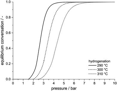
Hydrogen release from H18-DBT leads to an increase in number of mole and thus volume. According to Le Chatelier's principle, high pressure inhibits dehydrogenation and favours its reverse reaction, i.e. hydrogenation.H0-DBT + 9H2 ![[left over right harpoons]](https://www.rsc.org/images/entities/char_21cb.gif) H18-DBT H18-DBT | (1) |
When the pressure is increased, the corresponding equilibrium conversion for dehydrogenation decreases and equilibrium conversion for hydrogenation increases. To shift the equilibrium from 90% dehydrogenation to 90% hydrogenation, hydrogen pressure has to be increased only by a factor of two to three. The factor increases with increasing temperature, i.e. the required pressure ratio between hydrogenation and dehydrogenation is slightly higher if temperature is high. Thermodynamically, a hot pressure swing hydrogen storage unit run at 290 °C can be operated at ambient pressure (or slightly above) for almost full hydrogen release, and at pressure of 4 bar for almost full hydrogen uptake. Higher pressure for hydrogenation is favourable for kinetic reasons, but not required by thermodynamics. Hence, the pressures achievable with current electrolysis systems (typically 10–30 bar) are thermodynamically fully sufficient for full H0-DBT hydrogenation at typical dehydrogenation temperatures which results in our new concept of a LOHC-based hot hydrogen storage system.
2. Experimental
Hydrogenation/dehydrogenation reactor set-up
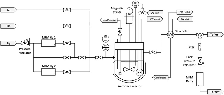
A schematic flow diagram of the experimental set-up used in this study is shown in Fig. 2.All experiments were performed in a 500 mL stainless-steel Parr batch autoclave (Type 4575/76 HP/HT) equipped with a four-blade gas entrainment stirrer (n = 1400 rpm). The reaction temperature was measured with two redundant thermocouples and controlled by a Parr Controller (Type 4848). The reactor was heated with an electric heating jacket. The cooling water (CW) in the cooling coil was provided by a cryostat (Huber Unichiller 015w-H) at a temperature of 16 °C. The pressure in the reactor was monitored by a pressure transmitter (WIKA Type S-20). The gas supply and discharge was carried out manually via needle valves. Samples of the liquid phase were taken through a sampling tube.
Prior to each experiment the reactor was purged with low-pressure nitrogen (grade 5.0 corresponding to a purity of >99.999%, Linde AG) to ensure inert atmosphere. High-pressure helium was used for leak tests. The pressure of hydrogen (grade 5.0 corresponding to a purity of >99.999%, Linde AG) was controlled by a pressure regulator. The amount of hydrogen catalytically bound to the carrier molecule H0-DBT during the hydrogenation experiment was determined by two Bronkhorst® Mass Flow Meters (FG-111B). These ensure a high dosing accuracy within a range between 50 and 15![[thin space (1/6-em)]](https://www.rsc.org/images/entities/char_2009.gif) 000 mL hydrogen per minute.
000 mL hydrogen per minute.
The low proportion of Hx-DBT, which is entrained as small droplets or evaporated in the released hydrogen, is knocked out or condensed in a countercurrent heat exchanger. In addition, an activated carbon filter protects the sensitive downstream components such as back pressure regulator and mass flow meter from traces of the LOHC components. The hydrogen release under dehydrogenation conditions is measured with a Bronkhorst® Mass Flow Meter (MFM Dehy, FG-111B) with a measurement range up to 5000 mL hydrogen per minute.
Hydrogenation/dehydrogenation swing experiments
All experiments were carried out using a 0.3 mass% Pt on alumina eggshell catalyst provided by Clariant, Heufeld, Germany. The catalyst pellets were ground in a planetary mill. The powder was sieved to a fraction smaller than 125 μm and vacuum dried at 110 °C for 12 hours.The reactor was filled with 300 g of H0-DBT (ca. 1.1 mol) and the dried catalyst powder. The molar catalyst to LOHC ratio was constant at 1![[thin space (1/6-em)]](https://www.rsc.org/images/entities/char_2009.gif) :
:![[thin space (1/6-em)]](https://www.rsc.org/images/entities/char_2009.gif) 6667 (0.015 mol%). The only exception was the first experiment at 290 °C where a ratio of 1
6667 (0.015 mol%). The only exception was the first experiment at 290 °C where a ratio of 1![[thin space (1/6-em)]](https://www.rsc.org/images/entities/char_2009.gif) :
:![[thin space (1/6-em)]](https://www.rsc.org/images/entities/char_2009.gif) 4000 (0.025 mol%) was applied. Inert atmosphere was ensured by repeatedly purging the reactor with nitrogen (5.0, Linde AG). The reactor was heated up to 20 K below reaction temperature and then pressurized with hydrogen. Subsequently, the first liquid sample was taken as reference.
4000 (0.025 mol%) was applied. Inert atmosphere was ensured by repeatedly purging the reactor with nitrogen (5.0, Linde AG). The reactor was heated up to 20 K below reaction temperature and then pressurized with hydrogen. Subsequently, the first liquid sample was taken as reference.
The reaction was started by stepwise increasing the stirrer speed to 1400 min−1 leading to the required hydrogen transfer into the liquid phase. The heat released by the exothermic hydrogenation reaction leads to a temperature increase to the desired reaction temperature that is kept constant by cooling. During the experiment, the reactor pressure was kept constant by continuous dosing of hydrogen. MFM Hy 1 or MFM Hy 2 determined the amount of consumed hydrogen, respectively.
The reactor was switched from hydrogenation to dehydrogenation mode by pressure adjustment at the back pressure regulator. By reducing the pressure in the reaction equilibrium shifted. Endothermal hydrogen release from the reactor was determined by the MFM Dehy.
Determination of the degree of hydrogenation
For quantitative comparison, the degree of hydrogenation (DoH) of a LOHC system is defined as the ratio of LOHC-bound hydrogen divided by the maximum hydrogen uptake capacity of the LOHC system under consideration. For the here reported experiments, the DoHi(t) after time t in each hydrogenation or dehydrogenation sequence i can be derived from eqn (2).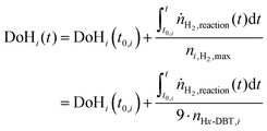 | (2) |
 | (3) |
Productivity is defined as the hydrogen uptake ΔmH2,x−y in a period of time Δtx−y per mass of platinum of the applied catalyst.
 | (4) |
Analytical methods to quantify LOHC decompositions products
Repeated hydrogenation and dehydrogenation of the Hx-DBT LOHC system imposes thermal stress on the system. In addition, the prolonged contact of LOHC compounds with the hydrogenation/dehydrogenation catalyst may act as cause for additional side-product formation. It is therefore of high interest for our study and the applicability of the proposed hot hydrogen storage concept to quantify all light or heavy boiling by-products that form during hydrogenation or dehydrogenation outside the intended H0-DBT/H18-DBT hydrogen storage cycle. Therefore the complete product spectrum, including light boilers down to C5 and C6 compounds and high boilers up to C100 compounds were evaluated by gas chromatography using a Thermo Fisher Scientific Trace 1310 gas chromatograph equipped with an Restek Rxi17Sil (30 meter, 0.25 mm) column.For the analysis of methane and light alkanes from high temperature hydrogenation gas phase samples, a Thermo Fisher Scientific Trace 1310 gas chromatograph equipped with a ShinCarbon ST 100/120 (2 meter, 1 mm) column and a flame ionization detector was applied. Gas phase samples were taken after 3 hours hydrogenation time.
3. Results and discussions
High temperature hydrogenation of H0-DBT
As described above, our hydrogen storage concept requires the use of a single catalyst or catalyst formulation for H0-DBT hydrogenation and H18-DBT dehydrogenation. It was known from our previous work10 that Ru on alumina, the well-established catalyst for the hydrogenation of H0-DBT, is not working well as dehydrogenation catalyst. Therefore, we decided to test first whether Pt on alumina, the most efficient H18-DBT dehydrogenation catalyst,10 shows any suitable catalytic activity in H0-DBT hydrogenation at the intended high hydrogenation temperatures.Remarkable H0-DBT hydrogenation activity was observed at temperatures above 220 °C for the investigated Pt on alumina catalyst. Fig. 3 summarizes the experimental results for the performed hydrogenation experiments in the temperature range between 160 and 311 °C at 30 bar hydrogen pressure. 30 bar hydrogenation pressure was selected to work with the typical hydrogen output pressure of a state-of-the-art PEM electrolyser.
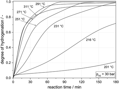 | ||
| Fig. 3 Hydrogenation of H0-DBT using Pt on alumina (0.015 mol% Pt applied as 0.3 mass% Pt loading, egg-shell) and 30 bar hydrogen pressure at different temperatures. | ||
At temperatures below 220 °C, signs of slow catalyst activation during the hydrogenation experiment were observed, but at these low temperatures, Pt on alumina still represents a mediocre H0-DBT hydrogenation catalyst. In contrast, full hydrogenation is achieved in all experiments above 230 °C with shorter and shorter reaction times required to reach a DoH of 1 (180 min at 231 °C vs. 85 min at 271 °C). At temperatures above 300 °C the influence of the thermodynamic hydrogenation/dehydrogenation equilibrium becomes visible. At 30 bar hydrogen pressure, the equilibrium at these temperatures does not allow full H18-DBT formation any longer. Instead, the reaction mixture remains at an unchanged DoH after a reaction time of ca. 120 min reflecting the respective equilibrium DoH at the applied temperature level (0.99 at 291 °C and 0.95 at 311 °C). A higher hydrogen pressure would be required at these temperatures to complete the hydrogenation process towards full loading. Note, however, that for stationary hydrogen and energy storage application the useable hydrogen storage capacity is not the most critical aspect as it only determines the tank size and the LOHC inventory for a given storage capacity. Both factors are less critical for the investment cost of the entire storage unit.
Fig. 4 highlights the fact that increasing hydrogenation temperatures lead to a strongly increasing hydrogenation productivity, with an onset around 200 °C. Initial hydrogenation productivities obtained for the DoH-range between 0.1 and 0.5 are shown as a function of temperature.
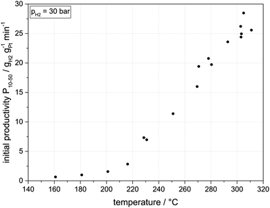 | ||
| Fig. 4 Initial hydrogenation productivity (DoHs between 0.1 to 0.5) as a function of temperature (30 bar hydrogen pressure, 300 g H0-DBT, 0.015 mol% Pt applied as 0.3 mass% Pt on alumina). | ||
Remarkably, at temperatures below 200 °C, the applied Pt on alumina catalyst is significantly less active than Ru on alumina. While for Ru on alumina at 180 °C a productivity of 2.0 gH2 gRu−1 min−1 has been reported,12 Pt on alumina shows at the same temperature only a productivity of 1.0 gH2 gPt−1 min−1. However, above 230 °C, a very significant increase in hydrogenation productivity is observed for the Pt-based hydrogenation catalyst with productivities rising almost linearly from 7.0 gH2 gPt−1 min−1 at 230 °C to above 25.0 gH2 gPt−1 min−1 at 300 °C. For the applied Pt mass of 32 mg this corresponds to a hydrogen consumption of 10 NL per minute (1.8 kWth). For the initial hydrogenation rates in the temperature range between 230 °C and 310 °C an Arrhenius activation energy of around 40 kJ mol−1 can be derived. This value suggests that the catalytic hydrogenation is influenced by pore diffusion effects in this temperature range under investigation.
In addition to liquid samples, also a gas phase sample was taken from the reactor after 3 hours hydrogenation time and analysed by gas chromatography. It was found that the detected methane concentration rises from 117 ppm for the hydrogenation reaction at 160 °C to 535 ppm at 231 °C, and 937 ppm at 311 °C. This indicates either a certain amount of methyl group cleavage from the DBT LOHC compounds or hydrogenation of carbon residues from the catalyst surface. Note, that the presence of methane neither harms the hydrogenation of H0-DBT,10 nor the dehydrogenation of H18-DBT or the fuel cell operation with the so-released hydrogen. The gas analysis further revealed that with increasing reaction temperature the content of carbon dioxide and propane increased, but all these traces remained in the double digit ppm range. Probably, these traces originate from impurities in the technical H0-DBT that was applied for these experiments. In the entire temperature range no carbon monoxide and no ethane could be detected in the gas phase.
Hydrogen storage experiments
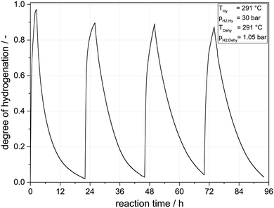
Having convincingly demonstrated that Pt on alumina is a very active H0-DBT hydrogenation catalyst, it was an obvious next step to try H0-DBT hydrogenation and H18-DBT dehydrogenation in the same reactor for several loading and unloading cycles. For a first experiment we performed the hydrogenation at 291 °C and 30 bar for 4 hours followed by a 20 hours dehydrogenation at 1.05 bar at exactly the same temperature. Fig. 5 shows the hydrogen uptake and release over four cycles.Under the applied conditions, DoHs of above 85% were reached in all hydrogen-loading sequences while the dehydrogenation sequences led in all subsequent cycles to DoHs of less than 10%. Thus, in all four cycles a hydrogen loading capacity of more than 4.6 mass% hydrogen or 1.54 kWh per kg LOHC material could be realized. From the first to the second hydrogenation/dehydrogenation cycle, a significant decrease in catalyst activity is evident (40% in hydrogenation productivity and 30% in dehydrogenation productivity). In the following hydrogenation/dehydrogenation cycles only a low catalyst deactivation (ca. 3% less productivity per cycle) was observed. A more detailed analysis of catalyst stability over several storage cycles is provided in the following section.
Hydrogenation at higher temperature than dehydrogenation
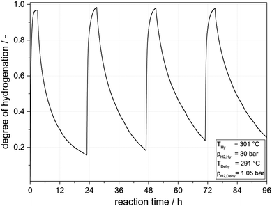
Following this very encouraging proof-of-concept experiments we were interested to raise the hydrogenation temperature level above the dehydrogenation temperature level. Our interest in this storage mode originated from the concept to export the hydrogenation heat into a heat storage device (e.g. a molten salt latent heat storage system). This would allow to import the hydrogenation heat in the next cycle for subsequent endothermic hydrogen release. To allow heat flow from the hydrogenation reactor to the heat storage system and later back to the reactor, a temperature difference of 10 °C was regarded as sufficient. Fig. 6 shows the results obtained. In comparison to the experiments shown in Fig. 5 the amount of catalyst was reduced from 0.025 mol% to 0.015 mol% to purposely avoid very deep dehydrogenation that was regarded as a potential reason for slight catalyst deactivation by coking.While the higher hydrogenation temperature leads to a higher DoH in the hydrogen-loading sequence even at lower catalyst loading, the lower catalyst loading leads to the expected, lower level of hydrogen release in the subsequent dehydrogenation sequence. In all four cycles DoHs above 0.95 were reached in the loading sequence, while the final DoH in the hydrogen-release step was always below 0.3. In total, all cycles realized a hydrogen storage capacity above 4 mass% hydrogen or 1.34 kWh per kg of LOHC material. Unfortunately, under the here applied process conditions, catalyst deactivation was slightly stronger as summarized in Fig. 7. It is noteworthy, however, that the strongest drop in activity took place between the first and the second cycle while both hydrogenation and dehydrogenation activity remained close to constant between cycles 3 and 4. This is a very interesting result as one can speculate that the repeated sequence of hydrogenation and dehydrogenation may also cause a catalyst regeneration effect during the hydrogenation cycle. It can be expected that carbon deposits formed during dehydrogenation at the very low pressure level applied (1.05 bar) will be removed from the Pt surface in the subsequent hydrogenation step. In this way our new reaction mode of operating hydrogen storage and release in the same reactor with the same catalyst opens a very interesting way to a process-integrated catalyst regeneration.
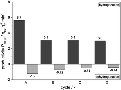 | ||
| Fig. 7 Catalyst productivities of the “Hot Hydrogen Storage” experiment shown in Fig. 6. | ||
Integrity of the LOHC carrier substance after hydrogen storage/release cycles
The here-applied hot storage conditions impose significant stress on the applied LOHC components in the reactor. The full volume of applied LOHC material is in contact with the catalyst during the entire cycling time under the relatively harsh reaction conditions applied. Therefore, our hydrogenation/dehydrogenation cycling experiments offer a very interesting way to study the stability of the H0-DBT/H18-DBT under water- and oxygen-free conditions and extended cycling times. Note that degradation of the LOHC carrier molecule can have – next to the obvious loss of storage volume – negative influences on physical and chemical properties of the carrier system. Light boiling decomposition products represent impurities in the obtained hydrogen and should be removed (e.g. by an active carbon filter) prior to hydrogen utilization in a fuel cell. High boiling products are assumed to act as precursors for coke formation and thus may have a negative influence on catalyst activity on the longer run.In all experiments described above, technical grade mixtures of H0-DBT isomers (technical grade Marlotherm SH from SASOL, Marl, Germany) were used. Note that the use of a technical mixture of DBT isomers was advised for this study as only the mixture of DBT regioisomers has the required low melting point (<−30 °C) for its use as technically relevant LOHC system. According to our analysis, the applied technical quality of Marlotherm SH contained 0.9 mass% of higher boiling components (bp at ambient pressure >390 °C) and less than 0.3 mass% of light boiling components (e.g. benzyltoluene, toluene) prior to any hydrogenation or dehydrogenation experiment. A liquid sample was taken once the reactor was heated to hydrogenation temperature for the first time and analysed for the content of low- and high-boiling compounds. These values were used as reference points for all later measurements.
During cycles A to D of Fig. 7 the molar content of heavy components increased from the original 0.9 to 2.1 mass%. At the same time the level of low-boiling by-products in the liquid samples slightly decreased and thus stayed below the reference value in all subsequent measurements. While we consider an increase of heavy by-products by 1.2 mass% over the 96 h operation time as still too high, the result is indeed encouraging. In our on-going studies we try to reduce this level of heavy formation by the following measures: (i) operation of hot hydrogen storage cycles with a distilled sample of Marlotherm SH as heavies present in the mixture from the beginning may trigger additional heavy formation; (ii) work with Pt catalyst on less acidic alumina as we have found out already that LOHC heavy formation is strongly dependent on support acidity; (iii) operate dehydrogenation cycle at slightly higher hydrogen back-pressure as we have seen strong evidence that heavies formation is suppressed by the presence of hydrogen at the catalyst surface. Storage cycles using 1.6 bar hydrogen pressure during dehydrogenation showed indeed a substantially lower formation of heavy components from the original 0.9 to 1.3 mass% within four cycles. With all the named measures we are confident to further improve the already quite impressive stability of our hot hydrogen storage system further.
4. Conclusion
This contribution presents major progress towards stationary hydrogen and energy storage using a cheap and non-toxic, pure hydrocarbon LOHC system.10 By demonstrating that H0-DBT hydrogenation and H18-DBT dehydrogenation can be performed in one reactor using the same catalyst at the same temperature level, four very important advantages in comparison to the actual state-of-the art using two separate hydrogenation and dehydrogenation reactors can be realized:• The reduction of the hydrogen storage system to only one reactor makes the whole storage device much simpler and saves a significant amount of investment and operation cost: only one reactor has to be connected, monitored, heated and maintained.
• Heating-up times represent a real problem for the process dynamics of the state-of-the-art two reactor LOHC hydrogen storage technology. This issue is convincingly solved by the new concept presented in this contribution: the one reactor applied for hydrogenation and dehydrogenation is always on the elevated reaction temperature of both processes. As either hydrogenation or dehydrogenation is carried out if the system is in operation, the reactor never cools down. When switching from hydrogenation mode to dehydrogenation mode, the reactor can immediately provide hydrogen from the pressurized vessel to the consumer, followed by dehydrogenation when the pressure reaches a level below 3 bar. Switching from dehydrogenation to hydrogenation mode, the first hydrogen produced by the electrolyser or provided by the hydrogen source can immediately be used to build up the hydrogen pressure in the reactor. Above 3 bar hydrogen pressure (depending on operation temperature), hydrogenation of the DBT mixture sets in. Thus, the here presented storage concept is characterized by extremely short response times and excellent dynamics.
• As demonstrated by our experiments, operating the hydrogenation sequence with 30 bar electrolyser pressure allows effective exothermic hydrogen loading at slightly higher temperatures than subsequent endothermic hydrogen release if the dehydrogenation pressure is below 2 bar. This creates suitable boundary conditions for the use of hydrogenation heat for dehydrogenation if an appropriate heat storage system is used. If the hot hydrogen storage system is connected to an industrial heat supply system (e.g. a high pressure steam system), the hydrogenation heat can be exported to the system at a higher temperature (and exergy) than the heat required for dehydrogenation. This may add an extra value to the hydrogen storage process.
• Finally, we found evidence that the repetitive use of the catalyst under high hydrogen pressure and low hydrogen pressure conditions has the additional advantage of catalyst regeneration under the high hydrogen pressure conditions. This adds another important advantage in comparison to the state-of-the art two reactor storage system. While a dehydrogenation-only reactor operates its catalyst always under the most stressful conditions (high temperature, low hydrogen partial pressure), the alternating operation conditions in the here-presented hot hydrogen storage system expose the catalyst to typical regeneration conditions in each hydrogenation sequence.
We conclude that the advantages of using one single hydrogenation/dehydrogenation reactor in LOHC-based stationary hydrogen storage are so overwhelming that this operation mode should become the standard for future decentralized or off-grid energy storage units using this technology. While there is still room for further research and development towards improving the LOHC technology per se (e.g. precious metal free catalyst systems, alternative LOHC systems or more efficient reactor concepts) this study demonstrates that heat integration between the hydrogen charging and the hydrogen discharging processes is indeed possible. These findings overcome a major concern regarding the efficiency of the LOHC technology and will broaden potential application fields for this technology.
Acknowledgements
The authors like to thank Dr Daniel Teichmann and Dr Normen Szesni for fruitful discussions and Clariant Produkte Deutschland for providing the applied catalyst. The authors acknowledge financial support by the German Science Foundation through its Erlangen Excellence Cluster “Engineering of Advanced Materials”. In addition, the authors gratefully acknowledge infrastructural support by the Free State of Bavaria through its Bavarian Hydrogen Center and by the Energie Campus Nürnberg.References
- T. He, Q. J. Pei and P. Chen, J. Energy Chem., 2015, 24, 587–594 CrossRef.
- P. Preuster, C. Papp and P. Wasserscheid, Acc. Chem. Res., 2017, 50(1), 74–85 CrossRef CAS PubMed.
- T. Schildhauer, E. Newson and S. Müller, J. Catal., 2001, 198, 355–358 CrossRef CAS.
- K. Müller, K. Stark, V. N. Emel'yanenko, M. A. Varfolomeev, D. H. Zaitsau, E. Shoifet, C. Schick, S. P. Verevkin and W. Arlt, Ind. Eng. Chem. Res., 2015, 54, 7967–7976 CrossRef.
- U. Eberle, M. Felderhoff and F. Schüth, Angew. Chem., Int. Ed., 2009, 48, 6608–6630 CrossRef CAS PubMed.
- G. P. Pez, A. R. Scott, A. C. Cooper and H. Cheng, US pat., US7101530 B2, 2006 to Air Products and Chemicals Inc., priority date: 06.05.2003.
- M. G. Manas, L. S. Sharninghausen, E. Lin and R. H. Crabtree, J. Organomet. Chem., 2015, 792, 184–189 CrossRef CAS.
- E. Newson, T. Haueter, P. Hottinger, F. von Roth, G. W. H. Scherer and T. H. Schucan, Int. J. Hydrogen Energy, 1998, 23(10), 905–909 CrossRef CAS.
- D. Teichmann, K. Stark, K. Müller, G. Zöttl, P. Wasserscheid and W. Arlt, Energy Environ. Sci., 2012, 5, 9044–9054 CAS.
- N. Brückner, K. Obesser, A. Bösmann, D. Teichmann, W. Arlt, J. Dungs and P. Wasserscheid, ChemSusChem, 2014, 7, 229–235 CrossRef PubMed.
- G. Do, P. Preuster, R. Aslam, A. Bösmann, K. Müller, W. Arlt and P. Wasserscheid, React. Chem. Eng., 2016, 1, 313–320 CAS.
- S. Dürr., M. Müller, H. Jorschick, M. Helmin, A. Bösmann, R. Palkovits and P. Wasserscheid, ChemSusChem, 2017, 10(1), 42–47 CrossRef PubMed.
Footnote |
| † Electronic supplementary information (ESI) available. See DOI: 10.1039/c7ee00476a |
| This journal is © The Royal Society of Chemistry 2017 |

