Alternative strategy for a safe rechargeable battery
M. H.
Braga
*ab,
N. S.
Grundish
a,
A. J.
Murchison
a and
J. B.
Goodenough
 *a
*a
aTexas Materials Institute and the Materials Science and Engineering Program, The University of Texas at Austin, Austin, TX 78712, USA. E-mail: jgoodenough@mail.utexas.edu
bCEMUC, Engineering Physics Department, Engineering Faculty, University of Porto, R. Dr. Roberto Frias s/n, 4200-465 Porto, Portugal. E-mail: mbraga@fe.up.pt
First published on 9th December 2016
Abstract
The advent of a Li+ or Na+ glass electrolyte with a cation conductivity σi > 10−2 S cm−1 at 25 °C and a motional enthalpy ΔHm = 0.06 eV that is wet by a metallic lithium or sodium anode is used to develop a new strategy for an all-solid-state, rechargeable, metal-plating battery. During discharge, a cell plates the metal of an anode of high-energy Fermi level such as lithium or sodium onto a cathode current collector with a low-energy Fermi level; the voltage of the cell may be determined by a cathode redox center having an energy between the Fermi levels of the anode and that of the cathode current collector. This strategy is demonstrated with a solid electrolyte that not only is wet by the metallic anode, but also has a dielectric constant capable of creating a large electric-double-layer capacitance at the two electrode/electrolyte interfaces. The result is a safe, low-cost, lithium or sodium rechargeable battery of high energy density and long cycle life.
Broader contextReduction of the dependence of modern society on fossil fuels is urgent. Electric power from wind and solar energy can be stored in a rechargeable battery. What is needed to reduce greenhouse gases is a safe, low-cost rechargeable battery with a high volumetric energy density and long cycle life for powering an all-electric road vehicle that is competitive in performance and in convenience with today's automobiles. The ability to plate dendrite-free alkali-metal anodes from a solid glass alkali-ion electrolyte with negligible anode/electrolyte interface impedance for transport of the working cation and a long cycle life at high rates has invited exploration of reversible plating of the alkali metal of the anode onto the cathode current collector. The voltage is limited by the energy difference between the Fermi levels of the anode and the cathode current collector, but the voltage can be tuned by a catalytic relay. Investigation of the concept with a copper current collector and an S8 or MnO2 catalytic relay has demonstrated proof of concept; with γ-MnO2 and a lithium anode, a discharge voltage of 3.08 V at commercial rates has been cycled over 250 times at room temperature with no lowering of the energy density. |
Introduction
Traditional rechargeable batteries use a liquid electrolyte and an oxide as a cathode host into which the working cation of the electrolyte is inserted reversibly over a finite solid-solution range. The energy-gap “window” Eg = 1.23 eV of an aqueous electrolyte restricts rechargeable batteries with a long shelf life to a voltage V ≲ 1.5 V. The organic-liquid electrolyte of the lithium-ion battery has an energy-gap window Eg ≈ 3 eV, but its LUMO is below the Fermi level of an alkali-metal anode, it is flammable, and it is not wet by an alkali-metal anode; therefore, the anode of a rechargeable battery having an organic-liquid electrolyte does not contain an alkali-metal component lest anode dendrites form and grow across the electrolyte to the cathode during charge to short-circuit the battery cell with incendiary consequences. Moreover, if the battery cells have an anode with a chemical potential (Fermi level) EF < 1.3 eV below the EF of lithium metal, a passivating solid/electrolyte interphase (SEI) is formed on the anode to prevent reduction of the electrolyte on contact with the anode. If the Li-ion battery is fabricated in a discharged state, as may be required for high-voltage cathodes, the Li+ of the SEI layer comes from the cathode, further restricting the operational capacity of the cathode. The carbon anodes of the Li-ion batteries that today power hand-held and portable devices have a low volumetric capacity and restrict the rate of charge since metallic lithium is plated on the carbon at higher charging voltages; also, oxide cathodes providing a cell voltage V > 4.3 V versus lithium tend to be unstable if overcharged. Therefore, the multiple cells of a large-scale battery stack require an expensive management system. Attempts to develop Li-alloy anodes have generally failed to provide the volumetric energy density required for portable batteries. Finally, sodium is cheaper than lithium and widely available from the oceans, which makes a sodium battery preferable to a lithium battery, but insertion hosts for Na+ have lower capacities than insertion hosts for Li+.In this paper, we report a new strategy for a safe, low-cost, all-solid-state rechargeable sodium or lithium battery cell that has the required energy density and cycle life for a battery that powers an all-electric road vehicle. The cells use a solid glass electrolyte having a Li+ or Na+ conductivity σi > 10−2 S cm−1 at 25 °C with a motional enthalpy ΔHm ≈ 0.06 eV,1,2 which promises to offer acceptable operation at lower temperatures; the glass also has a surface that is wet by metallic lithium or sodium, which allows reversible plating/stripping of an alkali-metal anode without dendrites, and an energy-gap window Eg > 9 eV that makes it stable on contact with both an alkali-metal anode and a high-voltage cathode without the formation of an SEI. The glass also contains electric dipoles that endow it with a large dielectric constant; its optimal properties are, therefore, only obtained after aging for over 10 days at 25 °C, but only for a few minutes at 100 °C.3 With this glass, a rechargeable battery with a metallic lithium or sodium anode and an insertion-compound cathode may require a polymer or liquid catholyte in contact with the cathode; but all-solid-state metal-plating batteries with the cathode strategy reported herein are simpler to fabricate at lower cost and offer much higher energy densities, longer cycle life, and acceptable charge/discharge rates.
Methods
The Li+ and Na+ glass electrolytes A2.99Ba0.005O1+xCl1−2x with A = Li or Na were prepared as previously described1,2 and were introduced, within a glovebox, into either a fiberglass sheet or a thin sheet of recycled paper from a slurry of glass particles in ethanol. The membranes were heated to T > 130 °C to outgas the ethanol of the applied electrolyte slurry and to reform the solid glass electrolyte without grain boundaries before being pressed against an anode of lithium or sodium foil contacting a stainless-steel cell container. The thickness of the electrolyte membrane was 0.06 mm. The cathode consisted of a redox center (an S8 or ferrocene molecule or an MnO2 particle) embedded in a mix of electrolyte and carbon contacting a copper current collector; the redox center could be removed. The cathode composite was pressed against the electrolyte membrane in a coin-cell configuration. The sealed cell was then aged for about 10 days at room temperature to allow the A2O and OA-electric dipoles of the glass electrolyte to coalesce into electric-dipole clusters containing negatively charged, ferroelectric molecular condensates. All the electric dipoles are aligned parallel to the axis of the internal electric field during charge and discharge.3 The thickness of the electrolyte membrane, the compositions of the composite cathodes, and the electrode/electrolyte interfaces were not optimized for maximizing the charge/discharge rates before measuring the preliminary performances of cell voltage, capacity, and cycle life reported herein.The tests were made by first measuring the open-circuit voltage with a Fluke voltmeter and then discharging the cell galvanostatically in a LANHE or an Arbin battery tester for a fixed amount of time before recharging, cycling, and finally disassembling. The cathode and anode of a Li–S disassembled cell that had been discharged for 28 days was examined visually and with SEM EDS to show that the anode lithium was plated on the cathode current collector during discharge.
Results and discussion
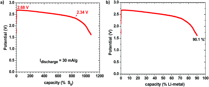
Fig. 1 shows the discharge voltage of a Li–S cell consisting of a metallic-lithium anode in contact with the Li-glass electrolyte and, as cathode, 1.99 mg of sulfur in a mixture of the glass electrolyte and carbon in contact with a copper current collector, measured over 28 days. The sulfur![[thin space (1/6-em)]](https://www.rsc.org/images/entities/char_2009.gif) :
:![[thin space (1/6-em)]](https://www.rsc.org/images/entities/char_2009.gif) electrolyte
electrolyte![[thin space (1/6-em)]](https://www.rsc.org/images/entities/char_2009.gif) :
:![[thin space (1/6-em)]](https://www.rsc.org/images/entities/char_2009.gif) carbon ratio was 47
carbon ratio was 47![[thin space (1/6-em)]](https://www.rsc.org/images/entities/char_2009.gif) :
:![[thin space (1/6-em)]](https://www.rsc.org/images/entities/char_2009.gif) 43
43![[thin space (1/6-em)]](https://www.rsc.org/images/entities/char_2009.gif) :
:![[thin space (1/6-em)]](https://www.rsc.org/images/entities/char_2009.gif) 10 wt%. Fig. 1(a) shows the measured discharge capacity of the cell versus the percentage available capacity for a cell reaction 16Li + S8 = 8Li2S, whereas Fig. 1(b) presents the same data versus the percentage available capacity of the lithium anode. The measured capacity was much greater than the capacity of the sulfur in the cathode, but it corresponds to 90.1% of the capacity of the lithium anode, which is much greater than the capacity of the sulfur. We therefore conclude that the sulfur acts as a redox center determining the voltage of the cell at which electrons from the anode reduce the Li+ at the electrolyte/cathode interface to plate lithium rather than reducing the sulfur, so long as the voltage remains above 2.34 V; below 2.34 V, the S8 molecules are reduced to Li2Sx (1 ≤ x ≤ 8) and the lithium on the anode becomes exhausted after 28 days in the cell of Fig. 1. The cell reaction was no longer reversible after this full discharge. At voltages V > 2.34 V, the cell is rechargeable and the sulfur is not reduced. The Fermi level of the lithium plated on the carbon–copper composite cathode current collector is determined by the Fermi level of the cathode current collector, whereas the Fermi level of the lithium anode remains that of metallic lithium, but the cell voltage is determined by the energy of the redox couple of the unreduced redox center.
10 wt%. Fig. 1(a) shows the measured discharge capacity of the cell versus the percentage available capacity for a cell reaction 16Li + S8 = 8Li2S, whereas Fig. 1(b) presents the same data versus the percentage available capacity of the lithium anode. The measured capacity was much greater than the capacity of the sulfur in the cathode, but it corresponds to 90.1% of the capacity of the lithium anode, which is much greater than the capacity of the sulfur. We therefore conclude that the sulfur acts as a redox center determining the voltage of the cell at which electrons from the anode reduce the Li+ at the electrolyte/cathode interface to plate lithium rather than reducing the sulfur, so long as the voltage remains above 2.34 V; below 2.34 V, the S8 molecules are reduced to Li2Sx (1 ≤ x ≤ 8) and the lithium on the anode becomes exhausted after 28 days in the cell of Fig. 1. The cell reaction was no longer reversible after this full discharge. At voltages V > 2.34 V, the cell is rechargeable and the sulfur is not reduced. The Fermi level of the lithium plated on the carbon–copper composite cathode current collector is determined by the Fermi level of the cathode current collector, whereas the Fermi level of the lithium anode remains that of metallic lithium, but the cell voltage is determined by the energy of the redox couple of the unreduced redox center.
In order to verify this conclusion, we disassembled the cell of Fig. 1 and examined the electrodes with the naked eye and with SEM EDS analysis, as shown in Fig. 2, which indeed shows lithium plated on the cathode current collector and no evidence of metallic lithium remaining on the stainless steel at the anode or the anode side of the electrolyte after full discharge of the lithium anode. The energy density of the full discharge was 10.5 W h g−1 (Li metal); but for the reversible voltage range Vdis > 2.34 V, it was 8.5 W h g−1 (Li metal).
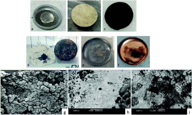 | ||
| Fig. 2 Images of the electrodes of a Li–S cell of Fig. 1. Before discharge: (a) Li anode on stainless steel, (b) glass electrolyte in cycled paper, (c) glass–sulfur–carbon mixture on cathode copper current collector. After full discharge: (d) cathode of glass-in-paper membrane and cathode copper current collector showing plating of Li on the cathode, (e) anode side of glass-in-paper membrane showing only glass-in-paper, (f) image of (e) after gold plating for SEM/EDS analysis, which gave no evidence of Li left on the anode, (g) SEM back-scatter radiation (×130 magnification) image showing only glass electrolyte on the anode side, (h) SEM back scatter radiation (×50 magnification) image of zone rich in plated lithium-composite cathode after plating (d) with Au, (i) the sulfur-rich zone of (h) ×130 magnification. | ||
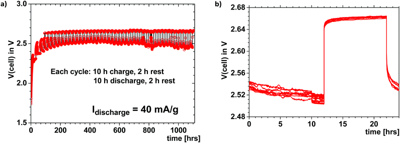
Fig. 3 shows the voltage of a Li–S cell like that of Fig. 1 that was cycled at 40 mA h g−1 for 10 h each way with a 2 h rest between charge and discharge. The charge and discharge voltages show a good coulombic efficiency over 1000 h; the cycling was continued beyond 46 cycles despite an imperfect seal of the cell. This Li–S cell with a plating cathode above 2.34 V is reversible, safe, with a large capacity retained over a long cycle life even though no attempt was made to optimize either the electrolyte thickness, the loading of sulfur in the cathode, or the electrode/electrolyte interfaces. The voltage of the cell was limited to avoid electrostatic energy storage at a high voltage, as has been demonstrated can occur.2
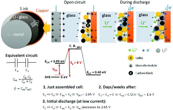
Fig. 4 shows a schematic of the all-solid-state Li–S cell with the glass electrolyte; during discharge the metallic-lithium anode is plated on the cathode carbon–copper composite current collector. We address the unusual variation of the cell voltage on discharge, starting with a variation of the open-circuit cell voltage VOC with time after cell assembly. We rationalize the observed phenomena based on capacitor association rather than on Fick's law for diffusion in the electrolyte and Debye's law for the charge separation of the electric-double-layer capacitance (EDLC) at an electrolyte/electrode interface as developed by Weppner4,5 since the electric dipoles in our electrolyte provide a stable major component to the EDLC. EDLCs CA and CC are formed, respectively, at the anode and the cathode electrode/electrolyte interfaces. These capacitances are connected in series, so the equivalent capacitance determining the cell voltage is as follows:
| Vcell = Q/Ceq | (1) |
| Ceq = CACC/(CA + CC) | (2) |
The total charge Q is a constant determined by that needed to equilibrate the electrochemical potentials of the two different electrodes. We measure μA = −3.05 V and μC = −0.40 V versus the standard hydrogen electrode (SHE) for metallic lithium and for sulfur, respectively. The chemical potentials μ < 0 reflect that the charge on the electron is negative (−e); in Fig. 4 we plot Fermi energies EF = −μ > 0 to reflect the energy differences EFA − EFC in eV, where e is the magnitude of the electron charge.
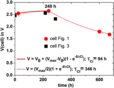
Since the total charge Q = CeqVcell of eqn (1) is constant, Vcell must increase as Ceq decreases. If CC ≪ CA, Ceq ≃ CC is small and Vcell = Vmax; if CA = CC = C, Ceq = C/2 is larger and Vcell= Vmin. Therefore, we can expect to find Vmin < Voc < Vmax initially after assembly of the Li–S cell. The simpler anode/electrolyte interface should result in CA ≫ CC and, from eqn (2), Ceq ≃ CC. CC increases with time as the electric-dipole component of the electrolyte interface charge is increased by dipole coalescence and condensation into ferroelectric molecules.3 However, at open-circuit voltage directly after cell assembly, CC may initially decrease with time as an insulating layer forms at the interface to increase the separation of the electrolyte and electrode surface charges. The initial increase of the Voc in Fig. 5 followed by a decrease signals a typical Voc(t) plot resulting from an initial decrease in CC followed by an increase in CC resulting from the slow evolution at room temperature of the electric-dipole component of the cathode EDLC. This phenomena, which is illustrated in Fig. 5, has been observed in many cells, and the initial Voc ≃ 1.65 V is typical of a well-aged cell before discharge is initiated.
On the initial discharge, Vcell of Fig. 1 increases at a fixed discharge current to a Vmax ≈ 2.65 V because the transport of electrons to the cathode reduces the induced electron holes at the surface, which attracts electrolyte Li+ back to the surface, thereby reducing CC and increasing Vcell to Vmax. This change is fast as it involves only electron and Li+ transport, but at Vmax there is an equilibrium between the rate of electron transfer to the cathode and the rate of plating of lithium by the transfer of the electrons to the Li+ at the surface of the electrolyte. During discharge, the transport of e− from the anode to the cathode via an external load is balanced by Li+ from the anode being transported to the cathode via the electrolyte as a result of the reaction Li0 = Li+ + e− so that CA and EFA remain nearly constant. At the cathode, the build-up of plated metallic lithium changes the morphology of the cathode to increase CC and create a very slow fade of Vcell with time of discharge.
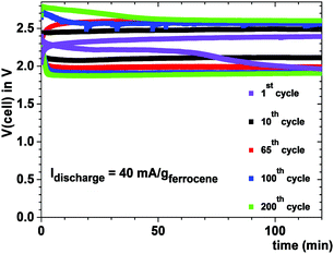
Fig. 6 shows the cell voltage of a Na–ferrocene cell with a copper cathode current collector that was cycled 200 times to illustrate a safe cell with a metallic-sodium anode contacting a Na-glass and a cathode with a ferrocene redox center; the ferrocene molecule was not oxidized. Plating of sodium from the anode onto the copper–carbon current collector eliminates the problem of identifying a cathode host for the insertion of Na+ with a high volumetric capacity; the volumetric capacity of this rechargeable sodium cell is large with a long cycle life.
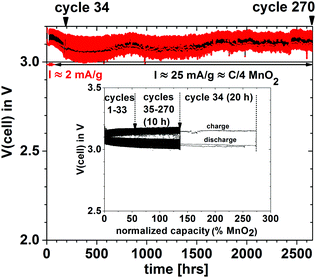
In order to demonstrate that a higher voltage can be obtained with a particle redox center of lower redox energy, we prepared a Li–MnO2 cell. Fig. 7 shows the voltage during charge and discharge at 25 mA g−1 for 4 h initially and for 20 h on the 34th cycle versus the % MnO2 capacity relative to the measured capacity. The 34th cycle gives a discharge/charge cycle with 3 times the capacity of the MnO2. Fig. 8(a) shows two light-emitting diodes (LEDs) lit by a Li–MnO2 coin cell that has a room-temperature voltage V > 3.0 V. The red LED requires a higher current and has a lower onset voltage than the blue LED. Fig. 8(b) shows a Li–S cell with a VOC = 2.61 V or V = 2.55 V when lighting a blue LED, showing an IRL drop of 0.06 V across the LED load.
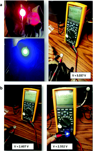 | ||
| Fig. 8 (a) A red and a blue LED lit by a Li–MnO2 coin cell at V > 3.0 V and (b) VOC of a Li–S coin cell without and with production of blue LED light. | ||
These illustrations demonstrate that the ability to plate/strip an alkali-metal anode in contact with a Li-glass or Na-glass electrolyte allows a totally unconventional strategy for the design of a rechargeable battery in which reversible plating of an alkali metal from the anode onto the cathode current collector gives a battery cell having a capacity determined by the amount of alkali metal used as the anode rather than the solid-solution range of the working ion in a host cathode lattice. The voltage is limited by the difference in the chemical potential of the alkali-metal anode and that of the cathode current collector, but it is determined by a cathode redox energy (if one is needed) that is above the Fermi level of the metallic cathode current collector. Without a redox center, the voltage is V ≈ 3.5 V.
Since the glass electrolyte is not reduced by the anode, no anode-electrolyte interphase (SEI) is formed, and since the electrolyte is wet by the anode, no anode or cathode dendrites are formed. Moreover, wetting of the electrolyte by the alkali metal anode allows volume changes at both the anode and the cathode during cycling to be accommodated by pressure from a spring at the back of one of the current collectors since the volume change of the electrodes is constrained to be perpendicular to the electrode electrolyte interface. The absence of an SEI on both electrodes and elimination of a large 3D insertion-particle volume change and/or small active electrode particles that limit volumetric capacity provide a simplified, low-cost structure in which the principal sources of capacity fade on cycling are not present. The result is a cheaper cell with a large volumetric capacity and a long cycle life. The cell voltages and rates are acceptable. All that remains to be optimized is the thickness of the solid glass electrolyte, the loading and choice of the redox center in the composite cathode to provide a required voltage, and optimization of the rate of ion transfer across the cathode/electrolyte interface to obtain a desired rate performance of the stored electric power. The impedance to plating of the metallic anode onto the cathode current collector during discharge depends on how the cell is assembled. Fig. 9 shows that the impedance at the anode/electrolyte interfaces in a symmetric Li/Li-glass/Li cell is negligible.
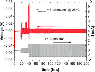 | ||
| Fig. 9 Chronopotentiometry measurements in a Cu//Li/Li-glass membrane/Li//Cu C2032 cell (with spring). | ||
Summary
The ability to plate/strip reversibly an alkali-metal anode from a solid electrolyte invites a complete rethink of rechargeable-battery strategies. With the Li-glass and Na-glass electrolytes, we have demonstrated in this paper one possible new strategy in which the cathode consists of plating the anode alkali-metal on a copper–carbon cathode current collector at a voltage V > 3.0 V. Replacement of a host insertion compound as cathode by a redox center for plating an alkali-metal cathode provides a safe, low-cost, all-solid-state cell with a huge capacity giving a large energy density and a long cycle life suitable for powering an all-electric road vehicle or for storing electric power from wind or solar energy.References
- M. H. Braga, J. A. Ferreira, V. Stockhausen, J. E. Oliveira and A. El-Azab, Novel Li3ClO-Based Glasses with Superionic Properties for Lithium Batteries, J. Mater. Chem. A, 2014, 2, 5470–5480 CAS.
- M. H. Braga, A. J. Murchison, J. A. Ferreira, P. Singh and J. B. Goodenough, Glass-Amorphous Alkali-Ion Solid Electrolytes and Their Performance in Symmetrical Cells, Energy Environ. Sci., 2016, 9, 948–954 CAS.
- M. H. Braga, J. A. Ferreira, A. J. Murchison and J. B. Goodenough, Electric Dipoles and Ionic Conductivity in a Na+ Glass Electrolyte, J. Electrochem. Soc., 2017, 164, A1–A7 Search PubMed.
- W. Weppner, Interfaces in Ionic Devices, Ionics, 2001, 7, 404–424 CrossRef CAS.
- W. Weppner, Engineering of Solid State Ionic Devices, Ionics, 2003, 9, 444–464 CrossRef CAS.
| This journal is © The Royal Society of Chemistry 2017 |

