 Open Access Article
Creative Commons Attribution 3.0 Unported Licence
Ligand-directed synthesis of {MnIII5} twisted bow-ties†
María José
Heras Ojea
 a,
Moya A.
Hay
 a,
Giacomo
Cioncoloni
a,
Gavin A.
Craig‡
a,
Giacomo
Cioncoloni
a,
Gavin A.
Craig‡
 a,
Claire
Wilson
 a,
Takuya
Shiga
b,
Hiroki
Oshio
 b,
Mark D.
Symes
 a and
Mark
Murrie
 *a
*a
aWestChem, School of Chemistry, University of Glasgow, University Avenue, Glasgow, G12 8QQ, UK. E-mail: mark.murrie@glasgow.ac.uk
bGraduate School of Pure and Applied Sciences, University of Tsukuba, Tennodai 1-1-1, Tsukuba 305-8571, Japan
First published on 31st July 2017
Abstract
Two isostructural polymetallic complexes [MnIII5(μ3-O)2(CH3COO)4(L1)4]− and [MnIII5(μ3-O)2(CH3COO)4(L2)4]− have been synthesised by using two Schiff base ligands derived from 3,5-diamino-1,2,4-triazole, following two different preparative routes, either using the pre-formed ligand (for L1) or via a metal-mediated template synthesis (for L2). The {MnIII5} structure is unusual, being based on two corner-sharing perpendicular {Mn3} triangles forming a twisted bow-tie. The magnetic studies reveal antiferromagnetic coupling between Mn(III) ions while electrochemical experiments are consistent with a quasi-reversible Mn(III)↔Mn(IV) redox process at the central manganese ion.
Introduction
Manganese is an excellent candidate for the synthesis and study of new molecular magnetic materials1–5 with a range of easily accessible oxidation states from Mn(II) to Mn(IV).6–8 Mn(III) ions are employed in the design of nanomagnets due to the characteristic magnetic anisotropy (D),9–12 whereas Mn(II) ions are used in molecular magnetic refrigerants, considering the relatively large number of unpaired electrons and the typical isotropic octahedral environment.13,14 In addition, the stability of these multiple oxidation states provides an opportunity to explore the redox properties in polymetallic Mn complexes.15–17 The synthetic routes to these complexes are mainly serendipitous self-assembly, which commonly uses flexible ligands, and/or rational design, which involves more rigid, polycompartmental ligands.18–20 One of the advantages of the second approach is the degree of control in the assembly of the metal ions through the pre-design of the ligand. Schiff base ligands have been used in this type of strategy,20–22 and in some cases, these ligands can provide additional redox properties to complexes as a result of the presence of iminic groups.23 Importantly, the iminic bonds make the ligand flexible enough to accommodate different coordination environments based on the type and/or valence of the metal ions. Considering these factors, we proposed the use of the 3,5-diamino-1,2,4-triazole derivatives, N-(2-hydroxy-3-methoxybenzylene)-3,5-diamino-1,2,4-triazole (H2L1) and N-salycilene-3,5-diamino-1,2,4-triazole (H2L2) to direct the synthesis of new polymetallic manganese complexes. Unlike other diamines, 3,5-diamino-1,2,4-triazole derivatives have not been explored in the synthesis, magnetic and electrochemical studies of high-nuclearity complexes. Herein we describe two different synthetic methodologies for the preparation of two new pentanuclear Mn(III) compounds, (HNEt3)[MnIII5(μ3-O)2(CH3COO)4(L1)4]·4CH3CN·4H2O (1) and (HNEt3)[MnIII5(μ3-O)2(CH3COO)4(L2)4]·CH3CN·2CH3OH (2) and report their structural, magnetic and electrochemical properties.Experimental section
Materials and physical measurements
All reagents and solvents were obtained from commercial suppliers and used without further purification.Crystallographic data were collected for 1 and 2 at 100 K using Mo-Kα radiation (λ = 0.71073 Å). For 1 a Bruker APEXII CCD diffractometer with an Oxford Cryosystems n-Helix low-temperature device mounted on a sealed tube generator was used; for 2 a Rigaku AFC12 goniometer equipped with an (HG) Saturn724+ detector mounted on an FR-E+ SuperBright rotating anode generator with HF Varimax optics (100 μm focus).24 Both structures were solved using SHELXT25 and refined using full-matrix least squares refinement on F2 using SHELX201426 within OLEX2.27 SQUEEZE was used to calculate and account for diffuse solvent in 2.28 Further details of disorder modelling and hydrogen atom treatment are given in the ESI.† The powder X-ray patterns for 1 and 2 were collected on a PANalytical XPert MPD, with Cu Kα1 radiation at ambient temperature over a range of 5° < 2θ < 50° using a step size of 0.0167°. The calculated pattern was generated from Mercury using the .cif of the crystal structure at 100 K.
The IR spectra were measured using a FTIR-8400S SHIMADZU IR spectrophotometer. The microanalyses and mass spectrometry analyses were performed by the analytical services of the School of Chemistry at the University of Glasgow. The 1H-NMR spectrum of H2L1 was obtained using a Bruker AVI 400 M MHz. Magnetic measurements of complexes 1 and 2 were carried out on phase-pure (Fig. S4 in the ESI†) polycrystalline samples that were lightly powdered and constrained in eicosane, using a Quantum Design MPMS-XL SQUID magnetometer. Data were corrected for the diamagnetic contribution of the sample holder and eicosane by measurements, and for the diamagnetism of the compounds. Electrochemical measurements were performed on a CH Instruments 760D Electrochemical Workstation using CHI Version 10.03 software. Electrochemical experiments for obtaining the cyclic voltammograms (CVs) were conducted at 298 K using a CH Instruments glassy carbon button working electrode (area = 0.071 cm2), BASi Ag/AgNO3 pseudo reference electrode, and Pt mesh counter electrode in a single compartment cell. Bulk electrolyses were performed in a similar manner, but using a large surface area reticulated glassy carbon electrode (BASi) as the working electrode. All electrode potentials were referenced to the ferrocene/ferrocenium couple by doping in samples of ferrocene to the electrolyte, and all potentials given in this work are reported relative to the ferrocene/ferrocenium couple. All electrochemical experiments were conducted in electrolyte solutions prepared using dry N,N-dimethylformamide (DMF), and were thoroughly degassed with argon. The supporting electrolyte was tetrabutylammonium hexafluorophosphate at a concentration of 0.2 mol dm−3. Solutions were agitated between acquisition of individual CVs and CVs were corrected for resistance, using the iR compensation function of the potentiostat. CVs were collected from unstirred solutions and bulk electrolyses were undertaken in stirred solutions.
Synthetic methods
![[double bond, length as m-dash]](https://www.rsc.org/images/entities/char_e001.gif) N), 12.13 (s; 1H, OH), 12.87 (s; 1H, NH). IR (
N), 12.13 (s; 1H, OH), 12.87 (s; 1H, NH). IR (![[small nu, Greek, macron]](https://www.rsc.org/images/entities/i_char_e0ce.gif) in cm−1): 3127 (m), 1651 (s), 1605 (s), 1469 (m) 1256 (s), 970 (s), 785 (s), 735 (s). MS (ESI+, m/z): 256 [C10H11N5O2 + Na]+.
in cm−1): 3127 (m), 1651 (s), 1605 (s), 1469 (m) 1256 (s), 970 (s), 785 (s), 735 (s). MS (ESI+, m/z): 256 [C10H11N5O2 + Na]+.
![[small nu, Greek, macron]](https://www.rsc.org/images/entities/i_char_e0ce.gif) in cm−1): 3385 (w), 1584 (s), 1431 (s), 1250 (s), 1215 (s), 974 (w), 746 (m), 606 (s). Elemental analysis: ((HNEt3)[MnIII5(μ3-O)2(CH3COO)4(L1)4]·5H2O) [%], found: C 39.68, H 4.34, N 17.58; calc.: C 39.10, H 4.44, N 17.73. MS (ESI−, CH3CN, m/z): 1469 [M]−. MS (ESI+, DMF, m/z): 1429 [M − OAc + H3O]+.
in cm−1): 3385 (w), 1584 (s), 1431 (s), 1250 (s), 1215 (s), 974 (w), 746 (m), 606 (s). Elemental analysis: ((HNEt3)[MnIII5(μ3-O)2(CH3COO)4(L1)4]·5H2O) [%], found: C 39.68, H 4.34, N 17.58; calc.: C 39.10, H 4.44, N 17.73. MS (ESI−, CH3CN, m/z): 1469 [M]−. MS (ESI+, DMF, m/z): 1429 [M − OAc + H3O]+.
![[small nu, Greek, macron]](https://www.rsc.org/images/entities/i_char_e0ce.gif) in cm−1): 3389 (w), 1585 (s), 1441 (m), 1404 (m), 1288 (s), 924 (m), 760 (s), 604 (s). Elemental analysis: ((HNEt3)[MnIII5(μ3-O)2(CH3COO)4(L2)4]·1.75CH3OH·5H2O) [%], found: C 38.78, H 4.37, N 18.29; calc.: C 38.97, H 4.55, N 18.44. MS (ESI+, CH3CN, m/z): 1372 [M + H + Na]+.
in cm−1): 3389 (w), 1585 (s), 1441 (m), 1404 (m), 1288 (s), 924 (m), 760 (s), 604 (s). Elemental analysis: ((HNEt3)[MnIII5(μ3-O)2(CH3COO)4(L2)4]·1.75CH3OH·5H2O) [%], found: C 38.78, H 4.37, N 18.29; calc.: C 38.97, H 4.55, N 18.44. MS (ESI+, CH3CN, m/z): 1372 [M + H + Na]+.
Results and discussion
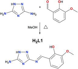
There are very few examples of complexes formed using 1,2,4-triazole derivatives where the magnetic properties have been investigated, these being mainly copper complexes.29–33 Surprisingly, there is a lack of magnetic studies performed on such complexes with other 3d ions (vide supra) such as Mn. Furthermore, the only report of the coordination chemistry of L1 and L2 is with oxovanadium(IV).34 H2L1 was prepared from the condensation reaction between 3,5-diamino-1,2,4-triazole and 2-hydroxy-3-methoxy-benzaldehyde (o-vanillin) in methanol. The synthetic route to H2L1 (Scheme 1) is simplified compared to that previously reported,34 as we obtained pure H2L1 straight from the condensation without re-crystallisation (checked by 1H NMR).34The reaction between H2L1 and Mn(CH3COO)2·4H2O in the presence of Et3N allows the assembly of (HNEt3)[MnIII5(μ3-O)2(CH3COO)4(L1)4]·4CH3CN·4H2O (1). An alternative synthetic route to that described for H2L1 was carried out to obtain H2L2 (see Fig. 1, left), based on the use of salicylaldehyde instead of o-vanillin. The condensation reaction to form the Schiff base was avoided as we were not able to isolate H2L2 as a pure product. Instead, a metal mediated template synthesis was used, yielding successfully the isostructural complex (HNEt3)[MnIII5(μ3-O)2(CH3COO)4(L2)4]·CH3CN·2CH3OH (2).35,36 Note that our attempts to form coordination complexes using the corresponding di-substituted 1,2,4-triazole ligands proved unsuccessful, and in the case of the reaction with Mn(CH3COO)2·4H2O the di-substituted ligand decomposed through breaking one imine bond to coordinate as H2L1 or H2L2.
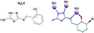 | ||
| Fig. 1 Ligand H2L2 (left), and general coordination mode of the deprotonated ligands (right). R = OCH3 for H2L1, and R = H for H2L2. | ||
X-ray crystallographic analysis
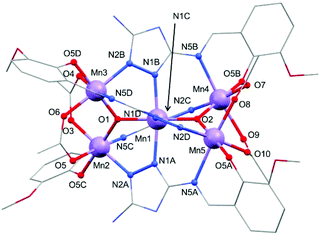
Selected crystallographic experimental details for 1 and 2 are shown in Table S1.† Both complexes crystallise in the monoclinic space group P21/n. The asymmetric unit of 1 and 2 contains one [MnIII5(μ3-O)2(CH3COO)4(L1)4]− anion (1) or [MnIII5(μ3-O)2(CH3COO)4(L2)4]− anion (2), one HNEt3+ cation, and several solvent molecules (four water and four acetonitrile molecules for 1; one acetonitrile and two methanol molecules for 2). Note that for 2 a poorly defined solvent region was additionally treated using SQUEEZE.28 The solvent accessible voids were calculated to be 190 Å3 containing 42 electrons per complex which can be attributed to 4 molecules of H2O, given the results from the elemental analysis. As both anionic complexes are isostructural, the following description is valid for 1 and 2 (see structure in Fig. S1 of the ESI†). The structure of 1 involves five Mn(III) ions arranged within two fused {Mn3O} units which share a central Mn(III) ion (Fig. 2). The oxidation state of each manganese centre has been confirmed by bond length and charge balance considerations, and also by bond valence sum calculations (BVS) with values presented in Table S2.†![[thin space (1/6-em)]](https://www.rsc.org/images/entities/char_2009.gif) 37 The two corner-sharing {Mn3O} units lie in planes almost perpendicular to one another with angles of 86.84° (1) and 86.75° (2) (see Fig. S2 of the ESI†). Each Mn(III) center displays a tetragonally distorted octahedral geometry through the coordination of four doubly deprotonated Schiff base ligands (L12− for 1, and L22− for 2) and four bidentate acetate auxiliary ligands (see Fig. 2). Two different Mn(III) ions can be distinguished based on the dissimilarities of their first coordination sphere (see Fig. 2 and Fig. S1 of the ESI†). The central Mn1 shared by the two fused {Mn3O} units is surrounded by four ligand units (L12− for 1, and L22− for 2) through the coordination of four N-donor atoms from the triazole rings. Moreover, two μ3-oxo bridges (O1, O2) fill the remaining equatorial positions of Mn1. These oxo groups also connect the central Mn1 ion with the outer manganese ions (Mn2, Mn3, Mn4, Mn5) with average Mn–O bond distances of 1.885(2) Å for 1 and 1.887(5) Å for 2. Each outer Mn(III) ion is further coordinated by one phenolic oxygen and two N atoms, a nitrogen from the triazole ring of one ligand and the iminic nitrogen of another. Two bidentate acetate anions are additionally bound which link each ion to the adjacent peripheral Mn(III) (see Fig. 2). The intramolecular Mn⋯Mn′ distances can be divided in two groups: those between the central manganese atom Mn1 and the peripheral ones Mn2–Mn5 (dAvgMn1⋯Mn′ = 3.252(8) Å for 1, and 3.253(1) Å for 2), and those between the outer Mn(III) ions linked by the acetate groups (3.291(7) Å for 1, and 3.300(1) Å for 2).
37 The two corner-sharing {Mn3O} units lie in planes almost perpendicular to one another with angles of 86.84° (1) and 86.75° (2) (see Fig. S2 of the ESI†). Each Mn(III) center displays a tetragonally distorted octahedral geometry through the coordination of four doubly deprotonated Schiff base ligands (L12− for 1, and L22− for 2) and four bidentate acetate auxiliary ligands (see Fig. 2). Two different Mn(III) ions can be distinguished based on the dissimilarities of their first coordination sphere (see Fig. 2 and Fig. S1 of the ESI†). The central Mn1 shared by the two fused {Mn3O} units is surrounded by four ligand units (L12− for 1, and L22− for 2) through the coordination of four N-donor atoms from the triazole rings. Moreover, two μ3-oxo bridges (O1, O2) fill the remaining equatorial positions of Mn1. These oxo groups also connect the central Mn1 ion with the outer manganese ions (Mn2, Mn3, Mn4, Mn5) with average Mn–O bond distances of 1.885(2) Å for 1 and 1.887(5) Å for 2. Each outer Mn(III) ion is further coordinated by one phenolic oxygen and two N atoms, a nitrogen from the triazole ring of one ligand and the iminic nitrogen of another. Two bidentate acetate anions are additionally bound which link each ion to the adjacent peripheral Mn(III) (see Fig. 2). The intramolecular Mn⋯Mn′ distances can be divided in two groups: those between the central manganese atom Mn1 and the peripheral ones Mn2–Mn5 (dAvgMn1⋯Mn′ = 3.252(8) Å for 1, and 3.253(1) Å for 2), and those between the outer Mn(III) ions linked by the acetate groups (3.291(7) Å for 1, and 3.300(1) Å for 2).
The outer manganese centres (Mn2–Mn5) in 1 and 2 display a characteristic elongated Jahn–Teller (JT) distortion (Fig. 3), as expected for high-spin d4 Mn(III) ions (dAvgMn–N = 2.298 Å (1), 2.283 Å (2); dAvgMn–N = 2.035 Å (1), 2.032 Å (2)). The elongated JT axis around the central manganese (Mn1) however is comparatively less distinct. This is evident on considering the bond lengths around Mn2–Mn5 as internal standards, and comparing these to those of Mn1. The Mn1–N distances (N1A–Mn1–N1B) are shorter than expected (2.162 Å (1), 2.158 Å (2)) and the Mn1–N distances (N1C–Mn1–N1D) are slightly longer than would be expected (2.096 Å (1), 2.074 Å (2)) compared to those of the outer Mn(III) ions. This indicates possible disorder of the JT axis between these two positions.38 Note, the Mn1–O1 and Mn–O2 distances are as expected on comparison to the other Mn–O distances not situated along the JT axes of Mn2–Mn5. We have therefore assumed the axis defined by O1–Mn1–O2 is not involved in the disorder.
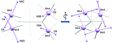 | ||
| Fig. 3 Detail of the metal core of 1. Only O, N, and metal ions involved in the Jahn–Teller (JT) axes of Mn2–Mn5 are labelled. JT axes are highlighted in lavender. | ||
An extensive search of the Cambridge Structural Database (CSD 5.38, June 2017) reveals the rarity of the metal-oxo assembly displayed for 1 and 2, as only five structures displaying a similar {M5O2} topology are reported (M being Mn, Fe, Co, Ni or Zn, and the bridging ligand an oxo or hydroxo group).39–41 It is important to stress that only one of the published structures is formed by Mn ions ([MnIII4MnIINa2O2(O2CMe)4(L′)4(DMF)4(H2O)], where H2L′ = 2-hydroxyphenyl-1,3,4-oxadiazole-2(3H)-thione).41 Therefore, the topology displayed by 1 and 2 is quite unusual for manganese-based polymetallic complexes, especially compared with more common metal arrangements for Mn(II/III) ions, such as a butterfly-like assembly.5,42,43
Magnetic properties
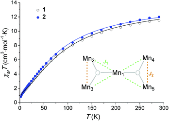
Variable-temperature magnetic susceptibility data were measured in an applied field of 1000 Oe in the range of 290 to 2 K (see Fig. 4). Variable-field magnetisation measurements were also carried out between 0 and 5 T at 2, 4 and 6 K for each complex (Fig. S6†). At 290 K the experimental χMT values observed for 1 and 2 (11.5 cm3 mol−1 K and 11.9 cm3 mol−1 K respectively) are lower than the theoretical spin-only value for five non-interacting Mn(III) ions (15.0 cm3 mol−1 K, considering S = 2, and g = 2). Below 290 K, the χMT value decreases, reaching a minimum value of 0.79 cm3 mol−1 K for 1 and 0.80 cm3 mol−1 K for 2 at 2 K, consistent with predominant intramolecular antiferromagnetic interactions. The susceptibility data for 1 and 2 were fitted using the program Phi,44 considering the magnetic model shown in Fig. 4 (inset) and the spin Hamiltonian shown below (eqn (1)).Initially zero-field splitting (ZFS) was not included to avoid over-parameterisation. Two different exchange interactions were considered for complexes 1 and 2 (see magnetic model above) – that between the central Mn1 and each of the outer-lying manganese centres  and the interaction between the Mn(III) centres of each peripheral pair
  . The g parameter was included as a fixed value of g = 1.98.45–47 The best fit gives the coupling constants
  (1), −2.82 cm−1 (2), and
  (1), −7.43 cm−1 (2) (R = 98% and 95%). Antiferromagnetic interactions are also seen in a mixed-valence {MnIII4MnII} complex with a related structure
  .41 Given the magnitude of the exchange interactions it is clear that axial zero-field splitting (D) should also be included, as this can be of the same order of magnitude as
  .3 However all attempts to include D lead to unreasonable values and/or prevent the fits from converging.
 | (1) |
The simple exchange-coupling model which ignores ZFS suggests that the ground state of both 1 and 2 is S = 0 with low-lying excited states: the closest lying S = 1 state within 3 cm−1 and the closest lying S = 2 state within 6 cm−1 (Fig. S5†). The magnetisation curves (Fig. S6†) would then result from population of these low-lying S > 0 states. Note that inclusion of single-ion ZFS in the model (vide supra) could modify the obtained  values and hence the ordering of the spin states, which may reveal a non-zero ground state. Additional alternating-current (ac) measurements were performed, with the absence of any frequency-dependent out-of-phase signal (Fig. S7†) consistent with either an S = 0 ground state or a small spin ground state with a negligible D parameter. Note that the Jahn–Teller axes of the four outer manganese ions are nearly perpendicular to each other (Fig. 3), which would yield a relatively small net axial magnetic anisotropy.48
Electrochemical studies
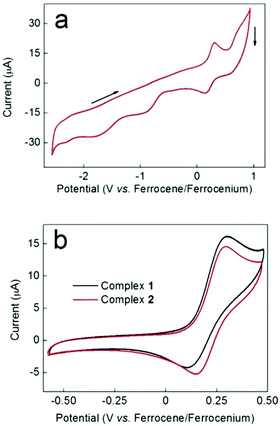
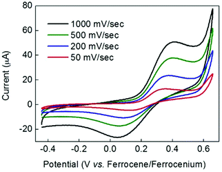
Along with the redox properties of the metal ions, Schiff base ligands can potentially impart intriguing redox activity to their complexes, as a result of the presence of iminic groups.49 The redox behavior of complexes 1 and 2 was therefore probed by cyclic voltammetry (CV). Fig. 5a shows the CV of compound 2 over the range +1 to −2.5 V vs. the ferrocene/ferrocenium couple (the CV of complex 1 over the same range is very similar). A CV of ligand H2L1 is provided in the ESI (Fig. S8†) for comparison. Fig. 5a indicates that at least two essentially irreversible reductive redox processes that cannot be attributed to the free ligand are evident at around −0.9 V and −1.8 V. These reductive waves did not become more reversible when the scan window was restricted. However, in the oxidative portion of the voltammogram, a more reversible wave (centred around +0.25 V) was apparent. Fig. 5b shows a comparison of the CVs for this oxidative process for complexes 1 and 2 over a smaller potential window than in Fig. 5a. Again, the free ligand shows no redox waves in this region (Fig. S8†). The shape profile was very similar in both cases, and E1/2 values of 0.21 V and 0.23 V were obtained for complexes 1 and 2 respectively (these values are the same within the ±20 mV error quoted for the type of Ag/AgNO3 pseudo reference employed). Taken together, and in view of the structural similarities between complexes 1 and 2, these data suggest that the redox process giving rise to this wave has the same origin in both complexes.Bulk electrolysis on complex 1 at +0.47 V indicated that the charge passed during this oxidation process was equal to 95% of that expected for a one-electron process. It is therefore plausible that this redox process corresponds to the one-electron oxidation and re-reduction of the unique, central Mn(III) centre Mn1 in these complexes given the different coordination environment displayed – {MnN4O2} – compared to Mn2–5 – {MnN2O4}. The kinetics of the redox process giving rise to the wave at +0.21 V for complex 1 were probed by scan-rate dependency studies. As is evident from Fig. 6, the return (cathodic) peak currents are always smaller than the oxidative currents, with this effect becoming less apparent as the scan rate is increased (i.e. the wave becomes more reversible the shorter the length of time the compound remains oxidised). This is consistent with an oxidation process followed by an irreversible chemical decomposition. Thus at fast scan rates, there is a greater chance that the complex can be reduced back to its original form before decomposition can occur. Moreover, Fig. 6 shows that even at slow scan-rates, the peak-to-peak separation is well over 100 mV, indicating that electron transfer is rather slow. This could imply that a structural re-arrangement occurs during this redox event and the associated geometrical changes required around a Mn(III) centre upon oxidation to Mn(IV) (and upon re-reduction to Mn(III)) could account for the slow electron transfer observed. It is interesting to note that the crystallographic analysis indicates possible disorder of the Jahn–Teller axis at the central Mn(III), which may make the redox event easier at this site.
Conclusions
We have shown for the first time that the 1,2,4-triazole derivatives H2L1 and H2L2 can be utilised in the synthesis of polymetallic transition complexes. This leads to two novel pentanuclear Mn(III)-based complexes with an unusual twisted bow-tie structure, where the Mn(III) ions are antiferromagnetically coupled. The electrochemical studies reveal a quasi-reversible redox process: a one-electron oxidation Mn(III) → Mn(IV) and re-reduction Mn(IV) → Mn(III) which we suggest to be centred at the central Mn(III) ion in both complexes. Future work will focus on modifying the Schiff base ligands to impart additional redox states towards redox-switchable molecular magnetic materials.Conflicts of interest
There are no conflicts to declare.Acknowledgements
The data which underpin this work are available at DOI: 10.5525/gla.researchdata.444. M. H. O. is thankful to the Japan Society for the Promotion of Science (JSPS) for the Short Term Pre/Postdoctoral Fellowship for International Research. We thank the EPSRC UK National Crystallographic Service for single crystal data collection. CCDC 1519689 and 1519690 contain the supplementary crystallographic data for this paper.†Notes and references
- G. Rajaraman, M. Murugesu, E. C. Sañudo, M. Soler, W. Wernsdorfer, M. Helliwell, C. Muryn, J. Raftery, S. J. Teat, G. Christou and E. K. Brechin, J. Am. Chem. Soc., 2004, 126, 15445–15457 CrossRef CAS PubMed.
- V. A. Milway, F. Tuna, A. R. Farrell, L. E. Sharp, S. Parsons and M. Murrie, Angew. Chem., Int. Ed., 2013, 52, 1949–1952 CrossRef CAS PubMed.
- G. A. Craig, J. J. Marbey, S. Hill, O. Roubeau, S. Parsons and M. Murrie, Inorg. Chem., 2015, 54, 13–15 CrossRef CAS PubMed.
- C.-I. Yang, W. Wernsdorfer, G.-H. Lee and H.-L. Tsai, J. Am. Chem. Soc., 2007, 129, 456–457 CrossRef CAS PubMed.
- G. E. Kostakis, A. M. Ako and A. K. Powell, Chem. Soc. Rev., 2010, 39, 2238–2271 RSC.
- T. Lis, Acta Crystallogr., Sect. B: Struct. Crystallogr. Cryst. Chem., 1980, 36, 2042–2046 Search PubMed.
- R. Sessoli, H. L. Tsai, A. R. Schake, S. Wang, J. B. Vincent, K. Folting, D. Gatteschi, G. Christou and D. N. Hendrickson, J. Am. Chem. Soc., 1993, 115, 1804–1816 CrossRef CAS.
- R. Sessoli, D. Gatteschi, A. Caneschi and M. A. Novak, Nature, 1993, 365, 141–143 CrossRef CAS.
- G. A. Craig and M. Murrie, Chem. Soc. Rev., 2015, 44, 2135–2147 RSC.
- K. S. Pedersen, J. Bendix and R. Clerac, Chem. Commun., 2014, 50, 4396–4415 RSC.
- P. L. Feng, C. Koo, J. J. Henderson, P. Manning, M. Nakano, E. del Barco, S. Hill and D. N. Hendrickson, Inorg. Chem., 2009, 48, 3480–3492 CrossRef CAS PubMed.
- P. Parois, S. A. Moggach, J. Sanchez-Benitez, K. V. Kamenev, A. R. Lennie, J. E. Warren, E. K. Brechin, S. Parsons and M. Murrie, Chem. Commun., 2010, 46, 1881–1883 RSC.
- M. Manoli, A. Collins, S. Parsons, A. Candini, M. Evangelisti and E. K. Brechin, J. Am. Chem. Soc., 2008, 130, 11129–11139 CrossRef CAS PubMed.
- G. Karotsis, S. Kennedy, S. J. Teat, C. M. Beavers, D. A. Fowler, J. J. Morales, M. Evangelisti, S. J. Dalgarno and E. K. Brechin, J. Am. Chem. Soc., 2010, 132, 12983–12990 CrossRef CAS PubMed.
- H. Y. V. Ching, E. Anxolabehere-Mallart, H. E. Colmer, C. Costentin, P. Dorlet, T. A. Jackson, C. Policar and M. Robert, Chem. Sci., 2014, 5, 2304–2310 RSC.
- D. Shevchenko, P. Huang, V. V. Bon, M. F. Anderlund, V. N. Kokozay, S. Styring and A. Thapper, Dalton Trans., 2013, 42, 5130–5139 RSC.
- H. Sato, M. Yamaguchi, T. Onuki, M. Noguchi, G. N. Newton, T. Shiga and H. Oshio, Eur. J. Inorg. Chem., 2015, 2193–2198 CrossRef CAS.
- R. E. P. Winpenny, J. Chem. Soc., Dalton Trans., 2002, 1–10 RSC.
- R. W. Saalfrank, H. Maid and A. Scheurer, Angew. Chem., Int. Ed., 2008, 47, 8794–8824 CrossRef CAS PubMed.
- T. Glaser, Chem. Commun., 2011, 47, 116–130 RSC.
- E. Colacio, J. Ruiz-Sanchez, F. J. White and E. K. Brechin, Inorg. Chem., 2011, 50, 7268–7273 CrossRef CAS PubMed.
- S. G. Dogaheh, M. Heras Ojea, L. R. Piquer, L. Artús Suàrez, H. Khanmohammadi, G. Aromí and E. C. Sañudo, Eur. J. Inorg. Chem., 2016, 20, 3314–3321 CrossRef.
- T. J. Dunn, C. F. Ramogida, C. Simmonds, A. Paterson, E. W. Y. Wong, L. Chiang, Y. Shimazaki and T. Storr, Inorg. Chem., 2011, 50, 6746–6755 CrossRef CAS PubMed.
- S. J. Coles and P. A. Gale, Chem. Sci., 2012, 3, 683–689 RSC.
- G. Sheldrick, Acta Crystallogr., Sect. A: Fundam. Crystallogr., 2008, 64, 112–122 CrossRef CAS PubMed.
- G. Sheldrick, Acta Crystallogr., Sect. C: Cryst. Struct. Commun., 2015, 71, 3–8 CrossRef PubMed.
- O. V. Dolomanov, L. J. Bourhis, R. J. Gildea, J. A. K. Howard and H. Puschmann, J. Appl. Crystallogr., 2009, 42, 339–341 CrossRef CAS.
- A. Spek, J. Appl. Crystallogr., 2003, 36, 7–13 CrossRef CAS.
- S. Ferrer, P. J. van Koningsbruggen, J. G. Haasnoot, J. Reedijk, H. Kooijman, A. L. Spek, L. Lezama, A. M. Arif and J. S. Miller, J. Chem. Soc., Dalton Trans., 1999, 4269–4276 RSC.
- S. Ferrer, J. G. Haasnoot, J. Reedijk, E. Müller, M. Biagini Cingi, M. Lanfranchi, A. M. Manotti Lanfredi and J. Ribas, Inorg. Chem., 2000, 39, 1859–1867 CrossRef CAS PubMed.
- S. Ferrer, E. Aznar, F. Lloret, A. Castiñeiras, M. Liu-González and J. Borrás, Inorg. Chem., 2007, 46, 372–374 CrossRef CAS PubMed.
- S. Ferrer, F. Lloret, E. Pardo, J. M. Clemente-Juan, M. Liu-González and S. García-Granda, Inorg. Chem., 2012, 51, 985–1001 CrossRef CAS PubMed.
- J. Hernández-Gil, N. Ovèjak, S. Ferrer, F. Lloret and A. Castiñeiras, Inorg. Chem., 2013, 52, 2289–2291 CrossRef PubMed.
- S. H. Sumrra and Z. H. Chohan, J. Enzyme Inhib. Med. Chem., 2013, 28, 1291–1299 CrossRef CAS PubMed.
- P. A. Vigato and S. Tamburini, Coord. Chem. Rev., 2004, 248, 1717–2128 CrossRef CAS.
- M. Andruh, Chem. Commun., 2011, 47, 3025–3042 RSC.
- I. D. Brown and K. K. Wu, Acta Crystallogr., Sect. B: Struct. Crystallogr. Cryst. Chem., 1976, 32, 1957–1959 Search PubMed.
- C. Murray, B. Gildea, H. Muller-Bunz, C. J. Harding and G. G. Morgan, Dalton Trans., 2012, 41, 14487–14489 RSC.
- J. Tabernor, L. F. Jones, S. L. Heath, C. Muryn, G. Aromi, J. Ribas, E. K. Brechin and D. Collison, Dalton Trans., 2004, 975–976 RSC.
- Y. Wei, H. Hou, Y. Fan and Y. Zhu, Eur. J. Inorg. Chem., 2004, 19, 3946–3957 CrossRef.
- C. Beghidja, G. Rogez and R. Welter, New J. Chem., 2007, 31, 1403–1406 RSC.
- J. Yoo, E. K. Brechin, A. Yamaguchi, M. Nakano, J. C. Huffman, A. L. Maniero, L.-C. Brunel, K. Awaga, H. Ishimoto, G. Christou and D. N. Hendrickson, Inorg. Chem., 2000, 39, 3615–3623 CrossRef CAS.
- R. McLellan, M. A. Palacios, E. K. Brechin and S. J. Dalgarno, ChemPlusChem, 2014, 79, 667–670 CrossRef CAS.
- N. F. Chilton, R. P. Anderson, L. D. Turner, A. Soncini and K. S. Murray, J. Comput. Chem., 2013, 34, 1164–1175 CrossRef CAS PubMed.
- G. Aromí, P. Gamez, O. Roubeau, P. C. Berzal, H. Kooijman, A. L. Spek, W. L. Driessen and J. Reedijk, Inorg. Chem., 2002, 41, 3673–3683 CrossRef.
- A. Konstantatos, R. Bewley, A.-L. Barra, J. Bendix, S. Piligkos and H. Weihe, Inorg. Chem., 2016, 55, 10377–10382 CrossRef CAS PubMed.
- C. J. Milios, A. Prescimone, A. Mishra, S. Parsons, W. Wernsdorfer, G. Christou, S. P. Perlepes and E. K. Brechin, Chem. Commun., 2007, 153–155 RSC.
- A. Ferguson, K. Thomson, A. Parkin, P. Cooper, C. J. Milios, E. K. Brechin and M. Murrie, Dalton Trans., 2007, 728–730 RSC.
- E. Castillo-Martínez, J. Carretero-González and M. Armand, Angew. Chem., Int. Ed., 2014, 53, 5341–5345 CrossRef PubMed.
Footnotes |
| † Electronic supplementary information (ESI) available: Crystallographic data, structure and detail of the crystal structure of 1 and 2, table with bond valence sum calculations, powder X-ray diffraction (PXRD) pattern of 1, further magnetic data and cyclic voltammetry of ligand H2L1. CCDC 1519689 and 1519690. For ESI and crystallographic data in CIF or other electronic format see DOI: 10.1039/c7dt02430d |
| ‡ Current address: Institute for Integrated Cell-Material Science (WPI-iCeMS), Kyoto University, Yoshida, Sakyo-ku, Kyoto 606-8501, Japan. |
| This journal is © The Royal Society of Chemistry 2017 |

