 Open Access Article
Creative Commons Attribution 3.0 Unported Licence
Monolithic porous magnesium silicide†
N.
Hayati-Roodbari
a,
R. J. F.
Berger
a,
J.
Bernardi
b,
S.
Kinge
c,
N.
Hüsing
 a and
M. S.
Elsaesser
*a
aChemistry and Physics of Materials, University of Salzburg, 5020 Salzburg, Austria. E-mail: michael.elsaesser@sbg.ac.at
bUSTEM, Technische Universität Wien, 1040 Vienna, Austria
cToyota Motors Company Europe, 2000 Antwerp, Belgium
First published on 12th April 2017
Abstract
Macroporous magnesium silicide monoliths were successfully prepared by a two-step synthesis procedure. The reaction of gaseous magnesium vapor with macro-/mesoporous silicon, which was generated from hierarchically organized meso-/macroporous silica by a magnesiothermic reduction reaction, resulted in monolithic magnesium silicide with a cellular, open macroporous structure. By adjusting the reaction conditions, such as experimental set-up, temperature and time, challenges namely loss of porosity or phase purity of Mg2Si were addressed and monolithic magnesium silicide with a cellular network builtup was obtained.
Introduction
In recent years, magnesium silicide (Mg2Si) has attracted more and more attention for applications in thermoelectric devices, anode materials for lithium ion batteries, and optics due to its low toxicity, unique optical and electrical properties along with low cost of production and its environmental compatibility.1–6In the synthesis of magnesium silicide mostly conventional preparation methods are applied, relying on solid state syntheses requiring melting, milling or mechanochemical approaches as well as annealing or combustion steps at high temperatures.7–10
Some drawbacks of these high-temperature routes are that the generation of free-standing porous or even nanostructured magnesium silicide structures is complicated or impossible and even the phase purity remains in some cases a challenge because the separation of magnesium silicide from, e.g. oxides such as silica or magnesium oxide is not trivial and the material is very prone to oxidation.7,11,12 In the presence of O2, Mg2Si decomposes to form MgO and Si.
So far, there have been only few reports on tailoring of the morphology of Mg2Si by nanostructuring or the introduction of porosity, although nanoscopic and porous structures promise improved performances or even completely new properties, such as drastically reduced thermal conductivities.13–18 Typical synthesis procedures for forming nanostructured Mg2Si are spark plasma sintering of nanopowders,19,20 solid-state phase transformation for nanowires,21 heat treatment of Si nanorods22 or reactive diffusion in a vacuum for thin films.23
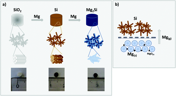
In the present work, we address the challenges of a deliberate tailoring of the porous morphology of phase pure magnesium silicide free-standing monoliths. To the best of our knowledge, this is the first report on the preparation of magnesium silicide monoliths with a cellular macroporous network comprising interconnected crystallites with sizes in the upper nanometer regime. We followed a two-step procedure, in which well-defined hierarchically organized meso/macroporous silica structures are first converted via a magnesiothermic reaction to hierarchically organized porous silicon, which in a second step is reacted with Mg to yield phase pure macroporous Mg2Si (see Fig. 1 for a schematic illustration).
Results and discussion
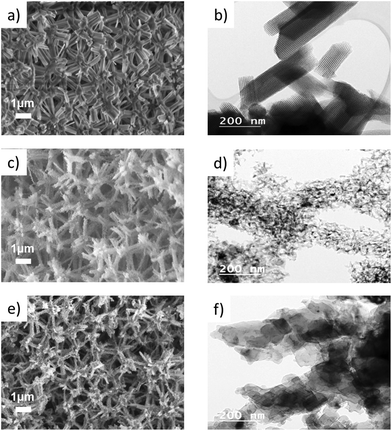
The formation of monolithic, porous Mg2Si by a gas phase reaction with magnesium requires a highly porous, mechanically and thermally robust precursor material to facilitate the necessary gas diffusion processes. In our recent work, we have shown that hierarchically organized, meso- and macroporous silica monoliths can successfully be converted to free-standing monolithic, meso- and macroporous silicon.24 The starting silica monoliths are typically characterized by a cellular structure forming a macroporous network with cell sizes >500 nm and in which the single struts are composed of amorphous silica exhibiting long-range periodic ordering of mesopores of 4 nm–7 nm diameter as seen in the SEM and TEM images in Fig. 2a and b, respectively.25 Upon treatment with magnesium vapor, the following reactions (eqn (1) and (2)) occur, leaving a material that contains Si and MgO as the main phases. Depending on the stoichiometry, temperature or reaction time appreciable amounts of magnesium silicide can be formed, which are typically removed by acid immersion. Non-reacting silica can easily be removed by etching with HF(aq).26–28| SiO2 + 2Mg → Si + 2MgO | (1) |
| SiO2 + 4Mg → Mg2Si + 2MgO | (2) |
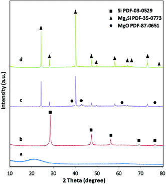
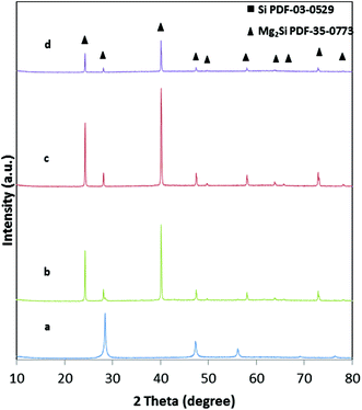
The X-ray diffraction patterns (Fig. 3) confirm the complete conversion of the amorphous silica with the typical broad reflection around 22°2θ to yield phase pure silicon. The broad reflections in the diffractogram of silicon already indicate the presence of very small crystallites with sizes of only 20–30 nm. The macroporous, cellular network structure is retained in the silicon network even after magnesiothermic treatment (Fig. 2c), however the periodically arranged mesopores within the struts are apparently replaced by 3D interconnected silicon grains (Fig. 2d). The empty mesoporous spaces are a clear indication that after the reaction with magnesium, first the mesopores in Si are blocked by MgO and subsequently accessible after leaching by acid immersion (HCl). This is supported by the complete loss of the specific surface area (SSA) after reaction with Mg into the Si/MgO composite. As listed in Table 1, the SSA decreases by conversion of silica to silicon due to (1) the conversion of the highly porous, amorphous network to nanocrystalline silicon and (2) the highly exothermic character of the reaction, which results in sintering processes. The pore size distribution of the mesopores is less uniform. However, the pore volume averages are almost identical.
It is well known that magnesium silicide is a by-product of the magnesiothermic reaction of silica with magnesium.26–28 Low reaction temperatures, short reaction times, a higher amount of magnesium, as well as an experimental set-up with short distances of the silica to the Mg source in principle favor the formation of magnesium silicide during the magnesiothermic reduction.24,27 It is, however, not possible to create free-standing 3D interconnected networks of phase pure Mg2Si crystallites following this procedure even with optimized reaction conditions. MgO is an inherent by-product of this reaction, and even if the stoichiometric ratio of Mg to SiO2 is adjusted to 4![[thin space (1/6-em)]](https://www.rsc.org/images/entities/char_2009.gif) :
:![[thin space (1/6-em)]](https://www.rsc.org/images/entities/char_2009.gif) 1, magnesium oxide is formed which cannot be removed easily from Mg2Si by acid treatment (eqn (2)).29
1, magnesium oxide is formed which cannot be removed easily from Mg2Si by acid treatment (eqn (2)).29
To overcome this problem, we subjected the preformed meso- and macroporous silicon monoliths to a second treatment with magnesium vapor in a molar ratio of 2.4![[thin space (1/6-em)]](https://www.rsc.org/images/entities/char_2009.gif) :
:![[thin space (1/6-em)]](https://www.rsc.org/images/entities/char_2009.gif) 1 (Mg
1 (Mg![[thin space (1/6-em)]](https://www.rsc.org/images/entities/char_2009.gif) :
:![[thin space (1/6-em)]](https://www.rsc.org/images/entities/char_2009.gif) Si). The two reactants (Mg and Si) are again spatially separated as described for the magnesiothermic reduction (Fig. 1 and eqn (3)) and a slightly higher amount of Mg than necessary was used, which has been accounted for the intrinsic impurities of MgO in Mg.24
Si). The two reactants (Mg and Si) are again spatially separated as described for the magnesiothermic reduction (Fig. 1 and eqn (3)) and a slightly higher amount of Mg than necessary was used, which has been accounted for the intrinsic impurities of MgO in Mg.24
| Si + 2Mg → Mg2Si | (3) |
One advantage of the spatial separation of the two precursors is that only Mg vapor is reacting with silicon, thus resulting in completely phase pure magnesium silicide as evidenced by X-ray diffraction (Fig. 3d). An example of the reaction product that is obtained by just mixing Mg and Si can be found in powder X-ray diffraction pattern (see Fig. 3c). The presence of MgO is clearly observable. Because of the porous silicon network, gas diffusion limitations of Mg vapor are low and a complete conversion is achieved in reasonable time. No silicon or magnesium oxide can be found in the product monoliths (Fig. 3d) under reaction conditions of 650 °C and 30 min. From the handling point of view, silica is hard and brittle, Si is soft and friable and Mg2Si is hard and brittle. The X-ray diffraction pattern confirms the presence of phase pure Mg2Si with crystallite sizes of 50 nm–100 nm as obtained from the Scherer equation.
One goal of this work was to preserve the macroscopic morphology of the monolithic pieces not only at the mm length scale but also at the micron length scale. SEM images of magnesium silicide show that the cellular network structure in the micrometer regime is still retained after the reaction of Si and Mg (Fig. 2e). However, the TEM image (Fig. 2f) shows rather dense, solid particles of sizes larger than 50 nm forming the strut network, which is in good agreement with the nitrogen sorption data (Table 1) illustrating a low specific surface area with no defined range for mesopores. The N2-sorption isotherms of samples during the different steps of reaction are provided in Fig. 2, ESI.†
The assumption that macropores, as well as small crystallites in the precursor network, facilitate the formation of phase pure Mg2Si has been confirmed by reacting non-porous commercial Si particles with particles sizes of 44 μm under the same reaction conditions (650 °C, 30 min, or 2 h). Even with longer reaction times, the reaction is not completed and silicon with large crystallite sizes remains in the sample (Table 1, ESI†).
One question to be answered was to what degree the reaction conditions influence the progress of the reaction and the structure of the final Mg2Si. Therefore, the reaction temperature has been varied between 600 °C and 700 °C and the reaction time between 30 min and 5 hours.
Influence of the reaction time
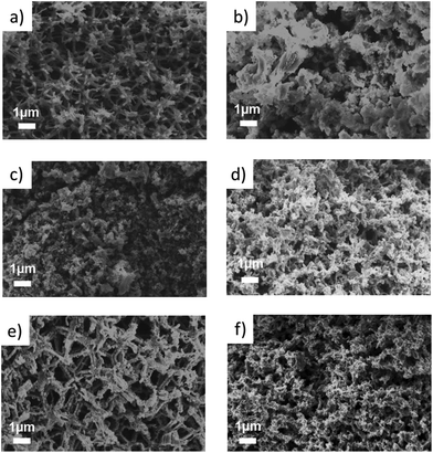
The X-ray diffraction patterns of samples that have been treated for different times at a reaction temperature of 650 °C are shown in the ESI (Fig. 1†). According to these XRD patterns, the formation of phase pure Mg2Si is evident for all samples. No extra crystalline phases are observed. As expected, longer reaction times result in slightly larger crystallite sizes increasing from 100 nm to 140 nm (Table 1, ESI†) as a result of heat-induced sintering processes.This trend is also confirmed by the SEM images (Fig. 4a and b). A clear difference in morphology can be observed after treating the sample for 5 hours at 650 °C. Sintering processes and agglomeration of the struts result in a deformed network with a higher density. A long reaction time may also risk the decomposition of Mg2Si into Mg and Si.30,31
Influence of the reaction temperature
The reaction temperature of 650 °C was chosen to ensure a reasonable rate of the magnesiothermic reduction, for which an onset temperature was investigated by DTA measurements. The influence of the reaction temperature on the final network structure was investigated by choosing a temperature below Tm of Mg and one higher than 650 °C. A temperature that is too low might result in an incomplete reaction as confirmed by the sample reacted at 600 °C, which shows approx. 7 wt% remaining silicon as evidenced by Rietveld refinement (Fig. 5). The crystallite size of the silicon residues with 25 nm is still in the lower nanometer regime; however, the size of the Mg2Si crystallites (128 nm) is comparable to the sample that has been treated at 650 °C. The macroporous, cellular network structure is still intact (Fig. 4c). A complete reaction can be achieved by increasing the reaction time from 30 min to 5 h, concomitantly with a deformation of the macropores as well as an agglomeration of the network constituting crystallites. In addition, a slight increase in the crystallite size (130 nm) is observed (Fig. 4d). At a reaction temperature of 700 °C (2 h), pure Mg2Si was obtained, but according to the SEM images (Fig. 4f), agglomeration takes place. Even a short reaction time of 30 min at 700 °C leads to the destruction of the macroporous, cellular structure, although the product composition is phase pure Mg2Si (Fig. 4e).Conclusions
Monolithic silicon has been converted for the first time to macroporous, cellular free-standing magnesium silicide monoliths following a two-step procedure. First, highly porous Si monoliths have been prepared by magnesiothermic reduction of a hierarchically organized meso-/macroporous silica network. The former ones have been reacted with Mg vapor at 650 °C for 30 min in a second step to give a cellular network of phase pure Mg2Si crystallites with sizes of about 100 nm. Reaction temperatures of 600 °C and 700 °C as well as longer reaction times of 2 h and 5 h show either unreacted Si in the sample or sintering phenomena resulting in less porous, more agglomerated network morphologies. The presence of macropores in the precursor network is an essential prerequisite for this gas phase reaction to reduce the diffusion limitation of Mg vapor to the reactive sites and yield phase pure Mg2Si.Experimental
Materials
Ethylene glycol (Aldrich) was purified by drying over Na2SO4 (Prolabo). Tetraethoxysilane (Merck), trimethylchlorosilane (Sigma-Aldrich), Pluronic-P123 (EO20PO70EO20, BASF), petroleum ether (40–60 °C, Prolabo), magnesium powder (for synthesis, Merck), hydrochloric acid (HCl, 37% Merck), acetic acid (CH3COOH, Glacial Merck) and hydrofluoric acid (40% Merck) were used without further purification.Hierarchically organized silica
Hierarchically organized meso-/macroporous silica (SiO2) was prepared according to Hartmann and Brandhuber et al. by sol–gel processing of tetrakis(2-hydroxyethyl)orthosilicate (EGMS) in an aqueous medium containing Pluronic P123™ and 1 M hydrochloric acid (HCl), with a composition by weight of Si/P123/0.1 M HCl = 8.4/30/70.25,32 After gelation, the wet gel bodies were allowed to age at 40 °C for seven days. To extract the surfactant, the whole gel body was immersed in a trimethylchlorosilane–petroleum ether (1![[thin space (1/6-em)]](https://www.rsc.org/images/entities/char_2009.gif) :
:![[thin space (1/6-em)]](https://www.rsc.org/images/entities/char_2009.gif) 10 wt/wt) solution for 10 hours. After washing with petroleum ether (three times) and ethanol (five times), the wet gels were sliced in small cylinders with a height of 3 mm–4 mm and dried by heating to 90 °C (heating rate of 1 °C min−1; holding time 24 h). The dried monoliths were calcined for 4 h at 550 °C in air.
10 wt/wt) solution for 10 hours. After washing with petroleum ether (three times) and ethanol (five times), the wet gels were sliced in small cylinders with a height of 3 mm–4 mm and dried by heating to 90 °C (heating rate of 1 °C min−1; holding time 24 h). The dried monoliths were calcined for 4 h at 550 °C in air.
Hierarchically organized silicon
For the magnesiothermic reduction reaction,24,26,27 the silica slices were placed on a stainless steel grid with magnesium powder beneath in a small boat under an argon atmosphere. The grid and boat were put in a stainless steel tube. The steel tube was heated in a tube furnace under an argon atmosphere to 650 °C at 1 °C min−1 heating rate and kept at this temperature for 2 h. The molar ratio of Mg![[thin space (1/6-em)]](https://www.rsc.org/images/entities/char_2009.gif) :
:![[thin space (1/6-em)]](https://www.rsc.org/images/entities/char_2009.gif) SiO2 was set to 2.4
SiO2 was set to 2.4![[thin space (1/6-em)]](https://www.rsc.org/images/entities/char_2009.gif) :
:![[thin space (1/6-em)]](https://www.rsc.org/images/entities/char_2009.gif) 1 to account for intrinsic impurities of MgO in Mg. For removal of the by-products (MgO, Mg2Si), the reaction product was wetted with 1 mL of degassed water, followed by a mixture of 20 mL of 2 M hydrochloric acid (HCl) and 10 mL of 50 wt% aqueous acetic acid (CH3COOH) for 3 h at 40 °C. Afterwards, washing with degassed water was repeated until the pH-value of the solution became neutral. The resulting brown monoliths were dried in a vacuum. The remaining silica was etched with 2 mL hydrofluoric acid (40% HF) diluted with 10 mL of distilled water and 10 mL of ethanol. Then the sample was again washed with degassed water until a neutral pH-value was reached and dried overnight at room temperature in a vacuum.24 The yield in this step of reaction is between 80 and 90% depending on the washing process and purity of magnesium. The presented conditions might vary if other porous materials are applied. Larger dimensions than 3 mm–4 mm of silica monoliths can cause diffusion problems.
1 to account for intrinsic impurities of MgO in Mg. For removal of the by-products (MgO, Mg2Si), the reaction product was wetted with 1 mL of degassed water, followed by a mixture of 20 mL of 2 M hydrochloric acid (HCl) and 10 mL of 50 wt% aqueous acetic acid (CH3COOH) for 3 h at 40 °C. Afterwards, washing with degassed water was repeated until the pH-value of the solution became neutral. The resulting brown monoliths were dried in a vacuum. The remaining silica was etched with 2 mL hydrofluoric acid (40% HF) diluted with 10 mL of distilled water and 10 mL of ethanol. Then the sample was again washed with degassed water until a neutral pH-value was reached and dried overnight at room temperature in a vacuum.24 The yield in this step of reaction is between 80 and 90% depending on the washing process and purity of magnesium. The presented conditions might vary if other porous materials are applied. Larger dimensions than 3 mm–4 mm of silica monoliths can cause diffusion problems.
Preparation of magnesium silicide
For the preparation of magnesium silicide, a similar set-up as described above has been used. The silicon monoliths were placed on a grid and separated from Mg in the boat beneath (molar ratio Mg![[thin space (1/6-em)]](https://www.rsc.org/images/entities/char_2009.gif) :
:![[thin space (1/6-em)]](https://www.rsc.org/images/entities/char_2009.gif) Si 2.4
Si 2.4![[thin space (1/6-em)]](https://www.rsc.org/images/entities/char_2009.gif) :
:![[thin space (1/6-em)]](https://www.rsc.org/images/entities/char_2009.gif) 1). Then the setup was placed in a stainless steel tube, which was heated in a tube furnace under an argon atmosphere to 650 °C at 1 °C min−1 heating rate and a holding time of 30 min (alternative synthesis parameters were 600 °C and 750 °C for 2 h or 5 h, respectively). The yield is higher than 95% for this step of reaction.
1). Then the setup was placed in a stainless steel tube, which was heated in a tube furnace under an argon atmosphere to 650 °C at 1 °C min−1 heating rate and a holding time of 30 min (alternative synthesis parameters were 600 °C and 750 °C for 2 h or 5 h, respectively). The yield is higher than 95% for this step of reaction.
Methods and analysis
Nitrogen sorption isotherms were obtained at 77 K using a sorption porosimeter (Micromeritics, ASAP 2420). The samples were degassed for 3 h at 100 °C in vacuo in the degas unit of the sorption apparatus. The Brunauer–Emmett–Teller (BET) surface area was evaluated using adsorption data in a relative pressure range p/p0 0.05–0.25. The mesopore size distribution was calculated on the basis of the desorption branch using the Barrett–Joyner–Halenda (BJH) model.Powder X-ray diffractograms (PXRD) were recorded using a BRUKER D8 DaVinci Design diffractometer using CuKα radiation (λ = 0.1542 nm), scanning from 5° to 80°2θ, at a step size of 0.02°, plus an integration time of 95.5 s. Evaluation of crystallite sizes was according to the Scherrer equation and Rietveld refinement was performed using TOPAS V4-2 software (Bruker).
The sample morphology was examined using a ZEISS/ULTRA PLUS scanning electron microscope operating at an accelerating voltage of 2 kV and using an in-lens detector. Silica samples were treated for conductivity reasons with gold sputtering.
The microstructure of the samples was studied by transmission electron microscopy (TEM) with a TECNAI F20 field emission electron microscope operating at an accelerating voltage of 200 kV. Images were recorded with a Gatan Orius SC600 CCD camera.
Acknowledgements
The help of G. Tippelt for the X-ray diffraction measurements and M. Suljic for the N2 sorption measurements is acknowledged. Financial support of Toyota Motors Company Europe is kindly appreciated.Notes and references
- J. M. Yan, H. Z. Huang, J. Zhang and Y. Yang, J. Power Sources, 2008, 175, 547–552 CrossRef CAS
.
- C. Zhang, D. Ni, Y. Liu, H. Yao, W. Bu and J. Shi, Nat. Nano, 2017, 12, 378–386 CrossRef CAS PubMed
.
- J. de Boor, U. Saparamadu, J. Mao, K. Dahal, E. Müller and Z. Ren, Acta Mater., 2016, 120, 273–280 CrossRef CAS
.
- J. De Boor, C. Gloanec, H. Kolb, R. Sottong, P. Ziolkowski and E. Müller, J. Alloys Compd., 2015, 632, 348–353 CrossRef CAS
.
- J. Santos-Peña, T. Brousse and D. M. Schleich, Ionics, 2000, 6, 133–138 CrossRef
.
- Y. Shen, J. Agric. Food Chem., 2017, 65, 995–1004 CrossRef CAS PubMed
.
- E. Godlewska, K. Mars, R. Mania and S. Zimowski, Intermetallics, 2011, 19, 1983–1988 CrossRef CAS
.
- E. Savary, F. Gascoin, S. Marinel and R. Heuguet, Powder Technol., 2012, 228, 295–300 CrossRef CAS
.
- A. Delgado, S. Cordova, I. Lopez, D. Nemir and E. Shafirovich, J. Alloys Compd., 2016, 658, 422–429 CrossRef CAS
.
- M. Ioannou, G. Polymeris, E. Hatzikraniotis, A. U. Khan, K. M. Paraskevopoulos and T. Kyratsi, J. Electron. Mater., 2013, 42, 1827–1834 CrossRef CAS
.
- M. Khajelakzay, S. R. Bakhshi and G. H. Borhani, Adv. Appl. Ceram., 2015, 114, 321–325 CrossRef CAS
.
- Y. He, Y. Liu, R. Ma, M. Gao and H. Pan, Ionics, 2015, 21, 2439–2445 CrossRef CAS
.
- G. H. Li, H. S. Gill and R. A. Varin, Metall. Trans. A, 1993, 24, 2383–2391 CrossRef
.
- K. Biswas, J. He, I. D. Blum, C.-I. Wu, T. P. Hogan, D. N. Seidman, V. P. Dravid and M. G. Kanatzidis, Nature, 2012, 489, 414–418 CrossRef CAS PubMed
.
- L.-D. Zhao, S.-H. Lo, Y. Zhang, H. Sun, G. Tan, C. Uher, C. Wolverton, V. P. Dravid and M. G. Kanatzidis, Nature, 2014, 508, 373–377 CrossRef CAS PubMed
.
- S. K. Bux, M. T. Yeung, E. S. Toberer, G. J. Snyder, R. B. Kaner and J.-P. Fleurial, J. Mater. Chem., 2011, 21, 12259–12266 RSC
.
- J. P. Heremans, M. S. Dresselhaus, L. E. Bell and D. T. Morelli, Nat. Nano, 2013, 8, 471–473 CrossRef CAS PubMed
.
- K. N. Galkin, N. G. Galkin, L. Dózsa, S. A. Dotsenko, I. M. Chernev, S. V. Vavanova, L. Dobos and B. Pécz, Phys. Status Solidi C, 2013, 10, 1720–1723 CrossRef CAS
.
- K. Arai, K. Nishio, N. Miyamoto, K. Sunohara, T. Sakamoto, H. Hyodo, N. Hirayama, Y. Kogo and T. Iida, MRS Proc., 2013, 1490, 63–68 Search PubMed
.
- M. Khajelakzay, S. R. Bakhshi, G. H. Borhani and M. Ramazani, Int. J. Appl. Ceram. Technol., 2016, 13, 498–505 CrossRef CAS
.
- Y. Kang, L. Brockway and S. Vaddiraju, Mater. Lett., 2013, 100, 106–110 CrossRef CAS
.
- W. Li, K. Nakane, M. Suzuki and H. Tatsuoka, Phys. Status Solidi C, 2013, 10, 1796–1799 CrossRef CAS
.
- I. Kogut and M. C. Record, Thin Solid Films, 2012, 522, 149–158 CrossRef CAS
.
- M. Waitzinger, M. S. Elsaesser, R. J. F. Berger, J. Akbarzadeh, H. Peterlik and N. Hüsing, Monatsh. Chem. – Chem. Mon., 2016, 147, 269–278 CrossRef CAS
.
- S. Hartmann, D. Brandhuber and N. Hüsing, Acc. Chem. Res., 2007, 40, 885–894 CrossRef CAS PubMed
.
- H. D. Banerjee, S. Sen and H. N. Acharya, Mater. Sci. Eng., 1982, 52, 173 CrossRef CAS
.
- K. Chen, Z. Bao, J. Shen, G. Wu, B. Zhou and K. H. Sandhage, J. Mater. Chem., 2012, 22, 16196 RSC
.
- H. N. Acharya, S. K. Dutta and H. D. Banerjee, Sol. Energy Mater., 1980, 3, 441–445 CrossRef CAS
.
- J. R. Szczech and S. Jin, J. Solid State Chem., 2008, 181, 1565–1570 CrossRef CAS
.
- E. Savary, F. Gascoin and S. Marinel, Dalton Trans., 2010, 39, 11074–11080 RSC
.
- E.-C. Stefanaki, E. Hatzikraniotis, G. Vourlias, K. Chrissafis, G. Kitis, K. M. Paraskevopoulos and G. S. Polymeris, Metall. Trans. A, 2016, 47, 5146–5158 CrossRef CAS
.
- S. Hartmann, M. S. Elsaesser and N. Hüsing, Z. Anorg. Allg. Chem., 2014, 640, 641–648 CrossRef CAS
.
Footnote |
| † Electronic supplementary information (ESI) available. See DOI: 10.1039/c7dt00571g |
| This journal is © The Royal Society of Chemistry 2017 |

