
 Open Access Article
 This Open Access Article is licensed under a Creative Commons Attribution-Non Commercial 3.0 Unported Licence
Completely integrated wirelessly-powered photocatalyst-coated spheres as a novel means to perform heterogeneous photocatalytic reactions†
B. O.
Burek
 a,
A.
Sutor‡
b,
D. W.
Bahnemann
c and
J. Z.
Bloh
*a
a,
A.
Sutor‡
b,
D. W.
Bahnemann
c and
J. Z.
Bloh
*a
aDECHEMA-Forschungsinstitut, Theodor-Heuss-Allee 25, 60486 Frankfurt am Main, Germany. E-mail: bloh@dechema.de; Web: http://dechema-dfi.de/TC.html
bDepartment of Sensor Technology, University of Erlangen-Nuremberg, 91052 Erlangen, Germany
cInstitut für Technische Chemie, Leibniz Universität Hannover, Callinstraße 3, 30167 Hannover, Germany
First published on 9th October 2017
Abstract
Heterogeneous photocatalytic reactions can be efficiently driven by completely integrated photocatalyst–light emitter units which are wirelessly powered from outside the reaction vessel using resonant inductive coupling. To demonstrate the universal applicability of the concept, three representative photocatalytic reactions, H2O2 production, methylene blue degradation and nitrobenzene reduction to aniline, were investigated.
Introduction
The importance of heterogeneous photocatalysis in fundamental and applied science has expanded rapidly over the last few decades1–3 and a variety of applications in the fields of organic synthesis,4,5 wastewater treatment6,7 and removal of air pollutants8,9 have emerged. Especially in the context of green chemistry, photocatalysis offers many advantages as high-energy conversions are possible under very mild conditions and by-products can often be avoided as photons are essentially traceless reagents.10,11 However, current photocatalytic processes have many engineering limitations such as illumination efficiency and reactor design, hence industrial implementation is still limited to select few cases and only on a small scale.12,13 Large-scale photocatalysis especially in the case of high catalyst loadings is limited mainly by the penetration depth of light into the reactor, which typically does not exceed a few millimeters. Reactors with a high surface-to-volume ratio such as photomicroreactors or falling film reactors show better illumination efficiencies but are very area-intensive in scale-up.14,15Internal illumination is a promising technique that achieves good illumination efficiency and enables a more flexible choice of reactor types. Different types of internal illumination such as immersion lamps16 or optical fibres17 have been successfully applied. Compared to those methods, wireless powering of internal light sources, further called Wireless Light Emitters (WLEs),18 has great advantages for up-scaling photocatalytic processes. Since the light sources themselves can easily be added to or separated from the reactor, it allows for more flexibility in selecting a suitable reactor. Even standard multi-purpose reactors can be used with WLEs to power photocatalytic reactions, which could tremendously help their widespread application.
Hayashi et al. showed that LEDs dispersed in a reactor and powered via piezoelectric effect by ultrasonic waves result in a higher photocatalytic methylene blue degradation rate compared to LEDs fixed to the wall of a reactor.19 Furthermore, microwave-powered electrodeless discharge lamps have often been utilized for photocatalytic degradation of organic pollutants in aqueous solutions.20,21 Resonant inductive coupling (RIC) shows great potential for wireless powering of LED devices as the possible energy transfer efficiency is already >75% (ref. 22) and the conductivity and permittivity of water show no negative impact on the energy transfer efficiency.23 Since there are already many well-known applications of RIC such as charging of batteries of portable devices,24 endoscopic capsules25 or other sensors,26,27 synergistic effects in future development can be expected. LEDs powered by RIC were successfully introduced as a means to illuminate photobioreactors28,29 and for photocatalytic wastewater treatment.30 In both cases, many WLEs in a suspension were powered by one transmitting inductor while a single WLE consists at least of one LED and an orientation-dependent receiving coil.
In order for the inductive coupling to be efficient, the WLE needs to be oriented with the receiving coil in parallel with the field-generating coils. Coincidentally, as the WLE's centre of mass is slightly below its geometric centre, they automatically align themselves correctly, enabling efficient power transfer even in fluidized-bed systems. Also, to receive power independent of the receiving coil orientation and illuminate the whole WLE surface uniformly, the use of a 3D receiving coil31 and two (up and down oriented) or even four (tetrahedral) LEDs is conceivable.
Furthermore, there is the challenge that the photocatalyst needs to be removed from the reaction medium after the reaction, not only to purify the product but also to recover and re-use the often expensive photocatalyst materials, which is technically challenging for very small nanoparticles. For this reason, it is advantageous to immobilize the photocatalyst onto larger supporting particles, which in this case can be the WLE itself. This makes separation and re-use of the catalyst trivial and allows for very easy operation of photocatalytic reactions as the photocatalyst, light source and power source are fully integrated in one easily operable small device. This approach has the additional advantage that light does not actually enter the reaction medium anymore since it is already fully absorbed by the photocatalyst coating, so reactions with strongly light-absorbing or light-sensitive reactants and products are easier to realize. These photocatalyst-coated WLEs can be treated the same way as common supported heterogeneous catalysts and can be operated in the same way, e.g. in fixed-bed or fluidized-bed systems by simply extending the reactor using a transmitting inductor (cf.Fig. 1).
 | ||
| Fig. 1 Photograph (left) of the modified photoreactor containing WLEs in a ferrioxalate solution with coated WLEs in front of the reactor and schematic view of the reactor (right). | ||
For these reasons, we developed photocatalyst-coated WLEs with a diameter of 1 cm which serve as a completely integrated, wirelessly powered catalyst system for heterogeneous photocatalytic reactions. The easy usability of this system is subsequently demonstrated for a variety of photocatalytic reactions. Each WLE consists of a receiving circuit and a UVA-LED (365 nm emission), which are housed in a spherical shell (cf.Fig. 2). As the shell material, a polymer is preferable since it can be easily processed using injection molding which facilitates mass production at very competitive prices.32 Transparent photocatalytic active coatings on polymers such as polycarbonate are also well known for the removal of pollutants.33–35 Unfortunately, many polymers are not UV-transparent and thus unsuitable for this application. Therefore, a high-performance UV-transparent cyclic olefin polymer (COP) was chosen as a shell material.
 | ||
| Fig. 2 Pictures of a WLE (a) and a coated WLE (b) and schematic view of the WLE and coating (c). | ||
Experimental
Film preparation and characterization
1 × 1.5 × 0.2 cm3 cyclic olefin polymer plane sheets (Zeonex 350R®, Zeon) and raw WLE spheres (injection molded, Kunststofftechnik Jantsch) were washed with ethanol (Roth, 99.8%) and dried with dry air. If a one-sided coating of the sheets was necessary (e.g. for measuring transmission spectra), the back side of the sheets has been masked with a strippable paint (Schmincke, Diaphoto film pelliculable rouge) which could easily be completely removed afterwards. To deposit the films, a normal sputtering machine (4-tec) was used. Since direct coating of the polymer with SiO2 was not successful, the surface was first activated in an O2 plasma (5 min, 5.5 sccm O2, 4 × 10⁻³ mbar, 30 WRF). The SiO2 coating was prepared by radio frequency (RF) magnetron sputtering, using a SiO2 target (Lesker, 99.995% purity) and Ar (1 h, 9 sccm Ar, 4 × 10⁻³ mbar, 100 WRF; for ignition, the pressure was set to 6 × 10⁻² mbar and slowly reduced afterwards). Before depositing the intermediate TiOx binding layer, the surface was cleaned in an Ar plasma (2 min, 9 sccm Ar, 5 × 10⁻³ mbar, 30 WRF). The film was prepared by direct current (DC) reactive magnetron sputtering of a Ti target (Lesker, >99.2% purity) using O2 and Ar gases (10 min, 8 sccm Ar, 4 sccm O2, 6 × 10⁻³ mbar, 50 WDC). The photocatalytically active TiO2 nanoparticle layer was prepared via dip-coating (LayerBuilder, KSV). 2 g TiO2 (Aeroxide P25, Evonik Degussa) was dispersed in 19 mL ethanol (Roth) and hydrochloric acid (1 ml, 2 M) with an ultrasonic glass finger (UP200St, Hielscher) for 2 minutes. After adding 85 μL tetrabutyl orthotitanate (Aldrich), the mixture was stirred at room temperature for 30 minutes. The polymer sheets were dip-coated in the suspension with a drawing speed of 1 mm s−1 and aged for 12 h at 80 °C.To analyze the coatings, a cross-section cut of the polymer sheets was prepared. The coated sheets were sputtered with gold and embedded under vacuum in an epoxy resin (SpeciFix-40, Struers) which was cured at 50 °C for 12 h. Subsequently, the samples were ground with an increasing grit (up to 2400 grit-paper) and polished with 3 μm and 1 μm diamond suspensions. For conductivity, the polished surface was coated with carbon and the resin with conductive silver. Element mapping of the cross-section was carried out via wavelength-dispersive spectroscopy (WDS) using an electron probe micro-analyzer (EPMA, JXA-8100, Jeol). To estimate the thickness of the SiO2 layer, an edge was created by masking a polymer sheet partially with adhesive tape for the sputtering. After removing the tape, the height of the edge was estimated via AFM (MultiMode with Nanoscope V, Bruker). The optical properties of the films were determined on a one side-coated polymer sheet with a UV/vis spectrophotometer (Flame S-UV-VIS-ES, Ocean Optics).
Evaluation of photocatalytic performance
The photocatalytic tests were performed in a cylindrical glass reactor (56 mm diameter, 105 mm height, about 100 ml volume). For reactions which needed gas supply, a reactor of the same dimensions extended by means of a quartz frit (30 mm diameter) melted on the bottom was used. The reactor was surrounded with three copper wire coils (18 turns each) in series with a distance of 20 mm mounted on a PMMA tube (75 mm diameter, 105 mm height). The coil was connected to a capacitor with an appropriate capacitance to generate a series resonant circuit with a resonance frequency of 178 kHz. This circuit was connected in parallel to an oscillator amplifier circuit with the same resonant frequency of 178 kHz. This frequency is also compatible with many inductive charging devices, e.g., the Qi standard. The WLE consisted of a ferrite core inductor (WE-PD2 4532 10 μH, Würth), a capacitor (82 nF) and a UV-LED (OCU-440 UE365-X-T, 365 nm peak emission, 350 mA, OSA Opto Light), connected all in parallel. These elements form an oscillating circuit with a certain resonance frequency and are encapsulated in a cyclic olefin polymer hollow sphere with a diameter of 10 mm. For the reactions, the WLEs were submerged in a fixed-bed-like arrangement on the bottom of the reactor in the respective solution. The gas volume flux of up to 60 mL min−1 did not disturb the fixed bed. However, higher flow rates can easily lift up the WLEs, whose density is only slightly above the density of water, leading to a fluidized bed operation mode. A picture of the reactor and the WLEs is shown in Fig. 1. The photon flux was determined using ferrioxalate actinometry36 with WLEs coated only with SiO2.Hydrogen peroxide production
The reactor was filled with the coated WLEs and phosphate buffer (0.1 M, pH 3) while it was continuously purged by oxygen bubbling (60 mL min−1) at room temperature. After 10 minutes in the dark, the electromagnetic field was switched on (19–20 V) to power the WLEs. At defined temporal intervals, 300 μl samples were taken from the reaction solution. To analyze the concentration of H2O2, a fluorometric method by Guilbault was adapted.37 Horseradish peroxidase (HRP) catalyses the dimerisation of p-hydroxyphenylacetic acid (POHPAA) in the presence of H2O2 which yields a detectable fluorescent product. Lyophilized powder of HRP (1 mg, 163 U mg−1, type II, Sigma) was dissolved in TRIS buffer (12.5 ml, pH 8.8, 1 M, Alfa Aesar). POHPAA (4 mg, Alfa Aesar, recrystallized twice from water) was also dissolved in TRIS buffer (12.5 ml). 12.5 μl of each solution was added to 100 μl of a sample containing H2O2 and the fluorescence signal (λex = 315 nm, λem = 406 nm, 25 °C) was determined using a microplate reader (Synergy Mx, BioTek). For the tests with TiO2 suspensions (0.05 g L−1, P25, Aldrich), WLEs coated only with SiO2 were used. To completely disperse TiO2 in the phosphate buffer, the suspensions were sonicated with an ultrasonic glass finger (2 × 5 s, 20% A). Before analytics, the TiO2 had to be filtered off through a syringe filter (0.2 μm, PVDF, Roth). For the reaction with a sacrificial reagent, 5 vol% 2-propanol (99.5%, Aldrich) was added to the buffer.Methylene blue degradation
The WLEs previously used for H2O2 build-up reactions were used for MB degradation after renewal of the dip-coating. The old coating was removed by ultrasound treatment and the WLEs were dip-coated as described above. Before photocatalytic decomposition of MB (Roth, λmax = 665 nm), the dye was adsorbed on the coated WLEs for 12 h in the dark (30 mL, 20 μM aqueous MB solution). Afterwards, the solution was replaced by the test solution (30 mL, 10 μM MB) and the WLEs were switched on using an electromagnetic field. To examine the decomposition of MB, 250 μL samples were taken every 20 minutes and the absorption at 665 nm was measured with a UV/vis microplate spectrophotometer (PowerWave HT, BioTek).Nitrobenzene reduction to aniline
The WLEs previously used for H2O2 build-up reactions and MB degradation were used for NB reduction after renewal of the dip-coating. The old coating was removed by ultrasound treatment and the WLEs were dip-coated as described above. The reactor was filled with five coated WLEs and nitrobenzene solution (20 mL, 10 mM NB, 99.5% Acros Organics) in 2-propanol while it was continuously purged by nitrogen bubbling (4 mL min−1). At defined temporal intervals, 250 μl samples were taken from the reaction solution and analyzed via GC-FID (Trace GC Ultra, Thermo Scientific, column: FS-Supreme-5 ms, CS Chromatographie, 30 m length, 0.25 μm film thickness, method: 70 °C for 2 min, 10 °C min−1 up to 240 °C, 25 °C min−1 up to 320 °C, 60 kPa constant pressure, splitless). The samples were diluted (1![[thin space (1/6-em)]](https://www.rsc.org/images/entities/char_2009.gif) :1) with an internal standard solution (10 mM quinoline in ethanol) by means of an autosampler (TriPlus, Thermo Scientific).
:1) with an internal standard solution (10 mM quinoline in ethanol) by means of an autosampler (TriPlus, Thermo Scientific).
Results and discussion
To immobilize the photocatalyst onto the WLEs, a multilayer coating has been successfully developed. A transparent thin SiO2 layer was first deposited on the COP. This intermediate layer protects the polymer from being photocatalytically oxidized38,39 and also enhances the adhesion between the organic polymer shell and the inorganic photoactive layer (TiO2). SiO2 was deposited via RF magnetron sputtering with a typical thickness of about 200 nm and transmission >96.5% at 365 nm. For better adhesion of the intermediate layer, the surface of the polymer was treated in oxygen plasma prior to SiO2 sputtering.40Before deposition of the photocatalyst, a thin TiOx layer was prepared via reactive DC magnetron sputtering of titanium to improve the binding between the photocatalyst particles and the SiO2 interlayer. This TiOx layer already absorbs about 5.5% of the light at 365 nm and shows slight photocatalytic activity (data not shown). These initial 3 process steps could all be carried out consecutively in the same chamber. For deposition of the photocatalyst, a dip-coating process based on commercial P25 TiO2 powder in acidified ethanol with tetrabutyl orthotitanate was used. The thickness of the layer was found to range between 1 and 4.5 μm with a transmission of <0.2% at 365 nm directly after preparation, indicating that virtually no UV light passes from the WLE into the reaction medium. Assuming a 1 μm thick layer, the mass of the catalyst is approximately 1 mg per WLE. Due to abrasion of the TiO2 during consecutive reactions, the transmission of the layer increases, indicating significant loss of TiO2 coating (cf. Fig. S1†). This shows that further improvement of the coating robustness is necessary. Nonetheless, the WLEs could be used for at least 9 consecutive reactions without any noticeable drop in performance. Furthermore, the coating could be completely regenerated by repeating the final dip-coating step. To characterize the coating, a cross-section of a coated COP sheet was studied by EPMA/WDS element mapping. Each layer shows full coverage and a uniform distribution of oxygen over the layers while silicon and titanium are separated in each layer (cf. Fig. S3†).
As has been pointed out by Camera-Roda and Santarelli, the use of counter-current illumination, i.e., opposing reactant and photon gradients, can lead to lower effectiveness factors when the turnover rate is high in comparison with the diffusion rate.41 There was no indication of this being a problem here but it needs to be kept in mind in the future optimization of the coating, especially when higher-power LEDs are used.
Before performing the photocatalytic reactions, the photon flux emitted by the WLEs was accurately determined using ferrioxalate actinometry. For this purpose, only SiO2-coated WLEs were used so that all the emitted light could pass into the reaction medium to be captured by the ferrioxalate solution. It was found that the photon flux increased linearly with the number of WLEs used, yielding 24 nE s−1 or 8 mW per WLE (cf.Fig. 3). For the following experiments, it was assumed that the photon flux measured this way was completely absorbed by the TiO2 coating.
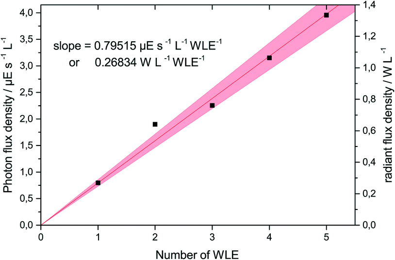 | ||
| Fig. 3 The photon flux density and radiant power density as a function of the number of used WLEs in 30 mL of solution, as determined by ferrioxalate actinometry. | ||
As a first target reaction, the photocatalytic production of H2O2 from molecular oxygen and water was studied (cf.Scheme 1). The coated WLEs were immersed in 30 mL of phosphate buffer (0.1 M, pH 3) in a fixed-bed-like arrangement. The generation of H2O2 follows the kinetics proposed by Kormann et al. and can be described with the respective model to extract generation and degradation rates, respectively.42
 | ||
| Scheme 1 Photocatalytic production of hydrogen peroxide from water and molecular oxygen using TiO2-coated WLEs. | ||
Experiments were performed with 1 to 5 WLEs either uncoated in a TiO2 suspension (50 mg L−1) or with TiO2 coated directly onto the WLE (1 mg per WLE), and representative concentration–time profiles are shown in Fig. 4. The H2O2 formation rate was 23 and 135 nM min−1 for 1 and 5 coated WLEs, respectively, confirming the expected linear scalability. The corresponding photonic efficiency is approximately 0.1%, which is in the range of other published values for the reaction (0.05% to 0.5%).42,43
 | ||
| Fig. 4 Concentration–time profiles for H2O2 formation with one (□) and five (▽) TiO2-coated WLEs (red) and uncoated WLEs in a TiO2 suspension (50 mg L−1) (black). The experimental conditions were as follows: 30 ml of 0.1 M phosphate buffer, pH = 3.0, 60 mL min−1 O2 bubbling. | ||
The formation rates are higher in a suspension (99 and 213 nM min−1 for 1 and 5 WLEs, respectively), presumably due to the better mass transport and higher surface area of freely moving individual nanoparticles. The difference of formation rates between coated and uncoated WLEs is smaller for 5 WLEs than for 1 WLE, presumably since the relative catalyst mass is increased in favour of the coated system. This also indicates that for a high density of WLEs, the coated system might perform similarly to a suspension, with the additional advantage that the catalyst can be much more easily removed and re-used. Since all components for the photocatalytic reaction are conveniently integrated in the WLE, the system would be perfect for in situ reactant generation for coupled H2O2-dependent reactions.44
As an additional test for the photocatalytic activity, the popular method, degradation of methylene blue (MB), which serves as a benchmark compound for photocatalytic wastewater treatment, was studied.45,46 Different amounts of coated WLEs were immersed in a fixed-bed-like arrangement in 30 mL of 10 μM MB solution. The decomposition of the dye on the WLEs' photocatalyst coating under internal light irradiation was examined by monitoring the absorption spectra via UV/vis spectroscopy. No appreciable degradation was observed in the dark or when a WLE without TiO2 coating was used. The decomposition rates were estimated from the initial decolouration rate using linear regression (cf.Fig. 5). The degradation rate again shows a roughly linear response with the number of WLEs with a slope of 5.5 nM min−1 per WLE. The average photonic efficiency was 0.015% which is in the range of values from other published thin TiO2 layers (0.009% to 0.078%).35,47 This is also an example where the target molecule absorbs some light itself which leads to light attenuation and might induce secondary photoreactions, which are effectively avoided by the present catalyst system.
 | ||
| Fig. 5 Degradation–time profiles for the decolouration of methylene blue with different amounts of WLEs in 30 mL of 10 μM aqueous MB solution and resulting degradation constants (kD(MB)) as a function of the number of WLEs. | ||
Finally, as an example of the applications in synthetic organic chemistry, the reduction of nitrobenzene with 2-propanol over illuminated TiO2 was demonstrated with the WLE system (cf.Scheme 2). In this reaction, nitrobenzene is photocatalytically reduced by a total of six electrons to aniline while simultaneously three 2-propanol molecules are oxidized to acetone.48
 | ||
| Scheme 2 Photocatalytic reduction of nitrobenzene with 2-propanol to aniline and acetone using TiO2-coated WLEs. | ||
Experiments were performed with 5 coated WLEs immersed in 20 mL of 10 mM nitrobenzene solution in 2-propanol. The concentrations of nitrobenzene and aniline were determined via GC analysis. Representative concentration–time profiles are illustrated in Fig. 6. The initially linear aniline formation rate was 0.94 mM h−1.
 | ||
| Fig. 6 Concentration–time profiles for the photocatalytic reduction of nitrobenzene to aniline. Reaction conditions were as follows: 5 coated WLEs, 20 ml 2-propanol, 10 mM nitrobenzene, 3 mL min−1 N2 bubbling. Solid lines represent a numerical non-linear fit using Langmuir–Hinshelwood kinetics. | ||
Interestingly, this reaction shows a remarkably high photonic efficiency of 26%, assuming six photons are required for each conversion. This value is extremely high for a heterogeneous photocatalytic reaction, most of which typically display efficiencies well below 10%, illustrated by the other two example reactions in this report. Also, other researchers have observed significantly lower values for the reduction of nitrobenzene,48 indicating that the WLE system is especially efficient for this reaction. There are also many similar photocatalytic reactions with nitroaromatic compounds, forming other interesting products such as quinoline derivatives or azo compounds, which could likely be performed with comparable efficiency.49
The presented system has a total power consumption of 8 W, invariant of the number of WLEs used here (1 to 5). This amounts to only 0.5% wall-plug efficiency (electrical power to radiant flux) for 5 WLEs (see the ESI† for product power consumption and CO2 balance data). However, this system was not optimized at all with respect to energy efficiency; assuming already published values for RIC (75%)22 and LED efficiencies (35%),50 it is possible to increase the energy efficiency by a factor of more than 50 to 26.3%, even more with expected higher LED efficiency in the future.
The density of WLEs can be best expressed as the fill factor (FF), i.e., the fraction of reactor volume that is taken up by the WLEs. In this demonstration, only a maximum fill factor of 7.7% was employed, indicating that tremendous intensification can be achieved simply by using a larger number of WLEs. Interestingly, the photon flux density increases exponentially rather than linearly with higher FF, as the total lamp power increases while the remaining liquid volume decreases. The theoretical maximum FF would be approximately 74% for the spherical WLEs (close-packing), a more realistic figure for practical applications is around 50%. Table 1 lists the principal parameters of the WLE system for these FFs, which would allow intensification by up to a factor of 34 compared to the present results simply by increasing the number of employed WLEs.
| WLE fill factor (FF) [−] | 74% | 50% | 7.7% |
|---|---|---|---|
| Geometric catalyst surface [cm2 L−1] | 8538 | 3000 | 250 |
| Catalyst mass [g L−1] | 5.44 | 1.91 | 0.16 |
| Radiant flux density [W L−1] | 43.49 | 15.28 | 1.27 |
| Photon flux density [μE L−1 s−1] | 132.7 | 46.6 | 3.9 |
| Space time yield [mM h−1] | 477.6 | 167.8 | 14.0 |
| Number of WLEs [L−1] | 5436 | 1910 | 159 |
When comparing these numbers with other light sources, it should be kept in mind that the data given here refers to the actual radiant flux incident in the reaction medium. When using for instance a medium-pressure mercury immersion lamp with 300 W electrical power, this lamp only has about 94 W irradiance due to heat losses and, of that, only about 25 W is emitted in the UVA region. So if used in a 1 L reactor, the effective radiant flux density of the lamp in the UVA region is not 300 W L−1 as might be assumed, but only 25 W L−1, even less when accounting for other types of losses. This is in the same range as can be achieved with the WLE system presented herein. It should also be considered that the LEDs used here have a relatively low average radiant flux of 8 mW, so using higher-power LEDs will increase the performance figures of the WLE system correspondingly.
The WLEs used here were manufactured in a small batch for a cost of 32 € per unit (see the ESI† for more details). However, considering the rapid decline in LED cost as well as economy-of-scale effects, their costs can likely be reduced to the order of 1 € per unit. The equipment for generating the inductive field is also inexpensive, even commercially available wireless phone chargers can be used to power the devices.
Conclusions
Even though heterogeneous photocatalytic processes have been shown to be very effective for many reactions, their industrial application is still limited to a few niche cases. The main reason for this is the need for custom reactor geometries which account for the poor light penetration depth in photocatalyst suspensions. So instead of making use of these advantageous processes, companies will instead favor less efficient, sometimes multi-step routes that do not need investment in additional equipment.In this report, we have demonstrated that photocatalyst-coated wireless light emitters can be used to power heterogeneous photocatalytic processes. Since both the light source and the photocatalyst are completely integrated in the WLE, they can be handled the same way as ordinary supported heterogeneous catalysts, e.g., in fixed-bed or fluidized-bed operation and in standard reactor geometries, eliminating the need for custom equipment or expertise in photocatalysis. The results also indicate that the reaction rate can be linearly increased with the number of WLEs, enabling easy scalability. This development might enable a more widespread application of photocatalytic processes as the equipment investment costs are drastically reduced to only the recyclable light sources. Also, the operator no longer needs background knowledge about photocatalysis or to expend any thoughts about the light sources and how to best transmit the light into the reactor, vastly facilitating the application of these reactions.
As an example of this technology, cyclic olefin polymer as a shell material for wireless light emitters has been successfully coated with a multilayer SiO2/TiO2 system resulting in small photocatalytically active spheres which could be powered wirelessly via inductive coupling while maintaining free mobility within the reaction medium. These coated WLEs were used to produce H2O2 and degrade methylene blue in aqueous solutions as well as reduce nitrobenzene to aniline in alcoholic solution, demonstrating the universal applicability of the concept.
Conflicts of interest
There are no conflicts to declare.Acknowledgements
Financial support by the German Research Foundation (DFG) is gratefully acknowledged (BL 1425/1-1). The authors also thank Zeon Europe GmbH for providing COP sheets, J. Bender, D. Hasenpflug, H. Kopietz, Dr. V. Kuznetsov, Dr. M. Rudolphi and Dr. G. Schmidt for support in preparing and characterizing the coating and Dr. M. Heining for his help and advice in designing the UV-WLE configuration.Notes and references
- B. Ohtani, J. Photochem. Photobiol., C, 2010, 11, 157–178 CrossRef CAS.
- J. Schneider, M. Matsuoka, M. Takeuchi, J. Zhang, Y. Horiuchi, M. Anpo and D. W. Bahnemann, Chem. Rev., 2014, 114, 9919–9986 CrossRef CAS PubMed.
- A. O. Ibhadon, P. Fitzpatrick, M. Sciences, C. Road, C. Innovation and C. T. Park, Catalysts, 2013, 3, 1–29 CrossRef.
- D. Friedmann, A. Hakki, H. Kim, W. Choi and D. Bahnemann, Green Chem., 2016, 18, 5391–5411 RSC.
- J. Z. Bloh and R. Marschall, Eur. J. Org. Chem., 2017, 2085–2094 CrossRef CAS.
- O. M. Alfano, D. Bahnemann, A. E. Cassano, R. Dillert and R. Goslich, Catal. Today, 2000, 58, 199–230 CrossRef CAS.
- S. Malato, P. Fernández-Ibáñez, M. I. Maldonado, J. Blanco and W. Gernjak, Catal. Today, 2009, 147, 1–59 CrossRef CAS.
- M. M. Ballari and H. J. H. Brouwers, J. Hazard. Mater., 2013, 254–255, 406–414 CrossRef CAS PubMed.
- J. Z. Bloh, A. Folli and D. E. Macphee, RSC Adv., 2014, 4, 45726–45734 RSC.
- V. Balzani, G. Bergamini and P. Ceroni, Angew. Chem., Int. Ed., 2015, 54, 11320–11337 CrossRef CAS PubMed.
- D. Ravelli, D. Dondi, M. Fagnoni and A. Albini, Chem. Soc. Rev., 2009, 38, 1999 RSC.
- T. Van Gerven, G. Mul, J. Moulijn and A. Stankiewicz, Chem. Eng. Process. Process Intensif., 2007, 46, 781–789 CrossRef CAS.
- C. McCullagh, N. Skillen, M. Adams and P. K. J. Robertson, J. Chem. Technol. Biotechnol., 2011, 86, 1002–1017 CrossRef CAS.
- P. S. Mukherjee and A. K. Ray, Chem. Eng. Technol., 1999, 22, 253–260 CrossRef CAS.
- W. Y. Teoh, J. A. Scott and R. Amal, J. Phys. Chem. Lett., 2012, 3, 629–639 CrossRef CAS PubMed.
- A. K. Ray and A. A. C. Beenackers, Catal. Today, 1998, 40, 73–83 CrossRef CAS.
- K. Hofstadler, R. Bauer, S. Novalic and G. Heisler, Environ. Sci. Technol., 1994, 28, 670–674 CrossRef CAS PubMed.
- A. Sutor, M. Heining, C. Lindenberger and R. Buchholz, IEEE Trans. Magn., 2014, 50, 2–5 CrossRef.
- N. Hayashi, R. Yasutomi and E. Kasai, Ultrason. Sonochem., 2010, 17, 884–891 CrossRef CAS PubMed.
- S. J. Hong and K. Y. Tam, Inf. Syst. Res., 2006, 17, 162–179 CrossRef.
- V. Církva, H. Žabová and M. Hájek, J. Photochem. Photobiol., A, 2008, 198, 13–17 CrossRef.
- J. Kuipers, H. Bruning, S. Bakker and H. Rijnaarts, Sens. Actuators, A, 2012, 178, 217–222 CrossRef CAS.
- J. Kuipers, H. Bruning, D. Yntema, S. Bakker and H. Rijnaarts, IEEE Trans. Ind. Electron., 2014, 61, 2356–2361 CrossRef.
- J. J. Casanova, Z. N. Low and J. Lin, IEEE Trans. Ind. Electron., 2009, 56, 3060–3068 CrossRef.
- R. Carta, G. Tortora, J. Thoné, B. Lenaerts, P. Valdastri, A. Menciassi, P. Dario and R. Puers, Biosens. Bioelectron., 2009, 25, 845–851 CrossRef CAS PubMed.
- J. De Boeij, E. Lomonova, J. L. Duarte and A. J. A. Vandenput, Sens. Actuators, A, 2008, 148, 319–328 CrossRef CAS.
- F. Lucklum and B. Jakoby, Sens. Actuators, A, 2008, 145–146, 44–51 CrossRef CAS.
- M. Heining and R. Buchholz, Biotechnol. J., 2015, 10, 1131–1137 CrossRef CAS PubMed.
- M. Heining, A. Sutor, S. C. Stute, C. P. Lindenberger and R. Buchholz, J. Appl. Phycol., 2014, 59–66 Search PubMed.
- J. Kuipers, H. Bruning, D. Yntema and H. Rijnaarts, J. Photochem. Photobiol., A, 2015, 299, 25–30 CrossRef CAS.
- R. Puers, R. Carta and J. Thone, J. Micromech. Microeng., 2011, 21, 15 CrossRef.
- M. Heckele and W. K. Schomburg, J. Micromech. Microeng., 2003, 14, R1–R14 CrossRef.
- R. Fateh, R. Dillert and D. Bahnemann, ACS Appl. Mater. Interfaces, 2014, 6, 2270–2278 CAS.
- R. Fateh, R. Dillert and D. Bahnemann, Langmuir, 2013, 29, 3730–3739 CrossRef CAS PubMed.
- R. Fateh, A. A. Ismail, R. Dillert and D. W. Bahnemann, J. Phys. Chem. C, 2011, 115, 10405–10411 CAS.
- C. G. Hatchard and C. A. Parker, Proc. R. Soc. A, 1956, 235, 518–536 CrossRef CAS.
- G. G. Guilbault, P. J. Brignac and M. Juneau, Anal. Chem., 1968, 40, 1256–1263 CrossRef CAS PubMed.
- Q. Geng, Q. Wang, Y. Zhang, L. Wang and H. Wang, Res. Chem. Intermed., 2013, 39, 1711–1726 CrossRef CAS.
- S. S. Ali, I. A. Qazi, M. Arshad, Z. Khan, T. C. Voice and C. T. Mehmood, Environmental Nanotechnology, Monitoring and Management, 2016, 5, 44–53 CrossRef.
- S. J. Hwang, M. C. Tseng, J. R. Shu and H. Her Yu, Surf. Coat. Technol., 2008, 202, 3669–3674 CrossRef CAS.
- G. Camera-Roda and F. Santarelli, Catal. Today, 2007, 129, 161–168 CrossRef CAS.
- C. Kormann, D. W. Bahnemann and M. R. Hoffmann, Environ. Sci. Technol., 1988, 22, 798–806 CrossRef CAS PubMed.
- G. Moon, W. Kim, A. D. Bokare, N. Sung and W. Choi, Energy Environ. Sci., 2014, 7, 4023–4028 CAS.
- A. E. W. Horst, S. Bormann, J. Meyer, M. Steinhagen, R. Ludwig, A. Drews and D. Holtmann, J. Mol. Catal. B: Enzym., 2016, 8–13 Search PubMed.
- A. Mills, C. Hill and P. K. J. Robertson, J. Photochem. Photobiol., A, 2012, 237, 7–23 CrossRef CAS.
- P. Aktivität and V. O. Bestimmung, Photokatalytische Aktivität von Oberflächen - Bestimmung der photokatalytischen Aktivität durch Abbau von Methylenblau, 2008, vol. 10, p. 52980 Search PubMed.
- J. Tschirch, D. Bahnemann, M. Wark and J. Rathouský, J. Photochem. Photobiol., A, 2008, 194, 181–188 CrossRef CAS.
- Y. Shiraishi, Y. Togawa, D. Tsukamoto, S. Tanaka and T. Hirai, ACS Catal., 2012, 2, 2475–2481 CrossRef CAS.
- A. Hakki, R. Dillert and D. Bahnemann, Catal. Today, 2009, 144, 154–159 CrossRef CAS.
- Datasheet for commercially available Lite-On 859-LTPL-C034UVH365 LEDs.
Footnotes |
| † Electronic supplementary information (ESI) available. See DOI: 10.1039/c7cy01537b |
| ‡ Present address: Institute of Measurement and Sensor Technology, UMIT - University for Health Sciences, Medical Informatics and Technology GmbH, Eduard-Wallnöfer-Zentrum, 16060 Hall in Tirol, Austria |
| This journal is © The Royal Society of Chemistry 2017 |